relay TOYOTA CAMRY V20 1986 Service Information
[x] Cancel search | Manufacturer: TOYOTA, Model Year: 1986, Model line: CAMRY V20, Model: TOYOTA CAMRY V20 1986Pages: 2389, PDF Size: 84.44 MB
Page 1078 of 2389
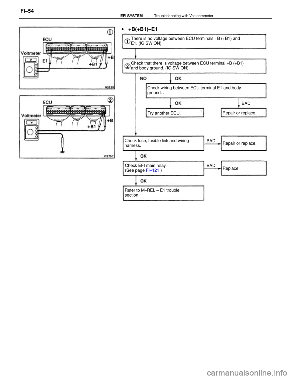
Check that there is voltage between ECU terminal +B (+B1)
and body ground. (IG SW ON) There is no voltage between ECU terminals +B (+B1) and
E1. (IG SW ON)
Check wiring between ECU terminal E1 and body
ground. .
Check fuse, fusible link and wiring
harness.
Refer to M±REL ± E1 trouble
section.Check EFI main relay.
(See page FI±121 )
w+B(+B1)±E1
Repair or replace. Try another ECU.Repair or replace.
Replace.BAD
BAD
BAD
± EFI SYSTEMTroubleshooting with Volt ohmmeterFI±54
Page 1087 of 2389
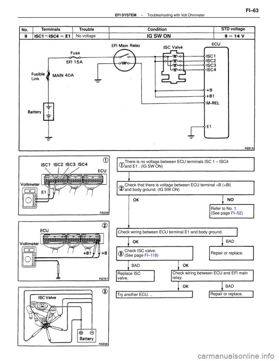
Check that there is voltage between ECU terminal +B (+Bl)
and body ground. (IG SW ON) There is no voltage between ECU terminals ISC 1 ± ISC4
and E1 . (IG SW ON)
Check wiring between ECU terminal E1 and body ground.
Check wiring between ECU and EFI main
relay. Check ISC valve.
(See page FI±118)Refer to No. 1.
(See page FI±52)
Try another ECU. ..Replace ISC
valve.
Repair or replace.Repair or replace.STD voltage
No voltage
IG SW ON
Terminals ConditionTrouble
BADBAD
BAD No.
± EFI SYSTEMTroubleshooting with Volt OhmmeterFI±63
Page 1135 of 2389
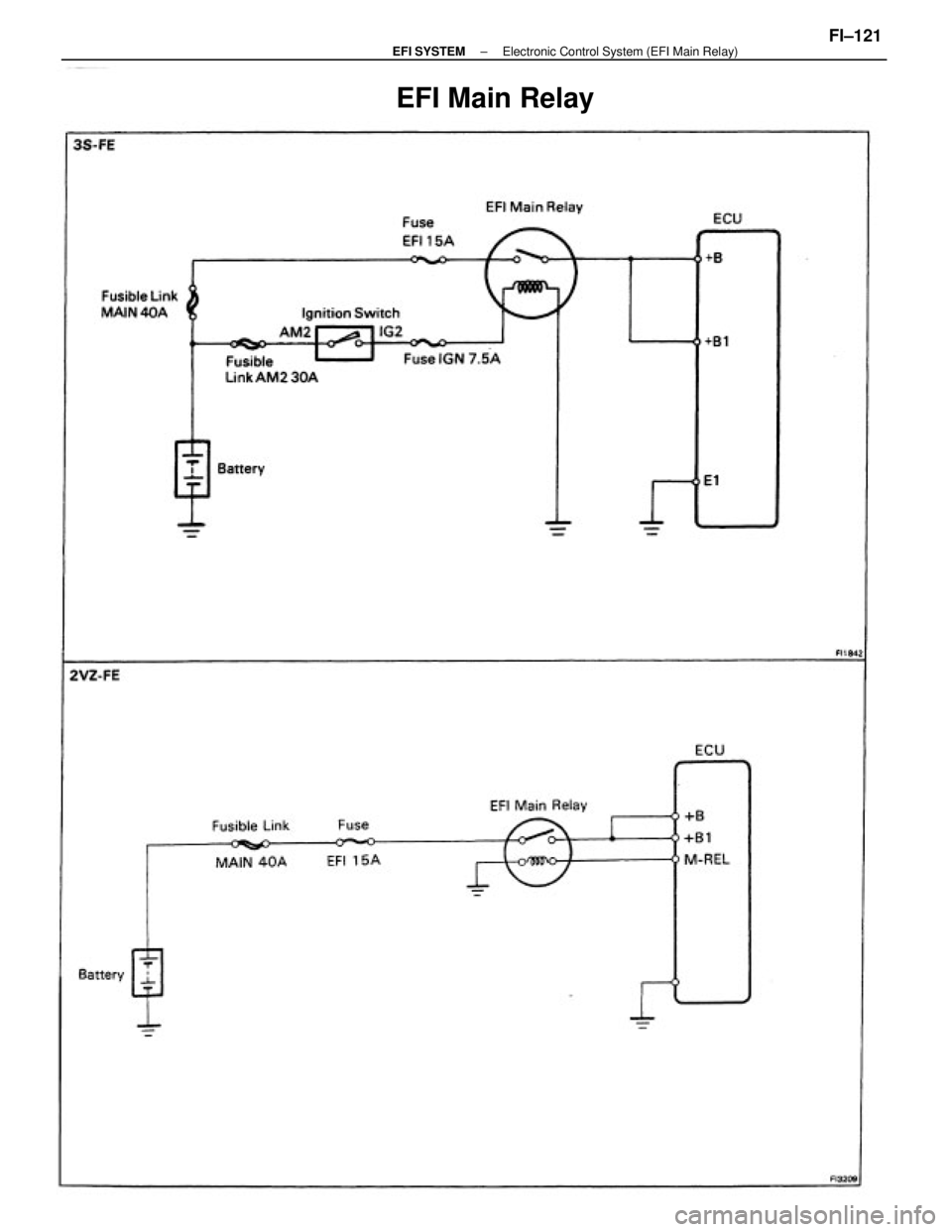
EFI Main Relay
± EFI SYSTEMElectronic Control System (EFI Main Relay)FI±121
Page 1136 of 2389
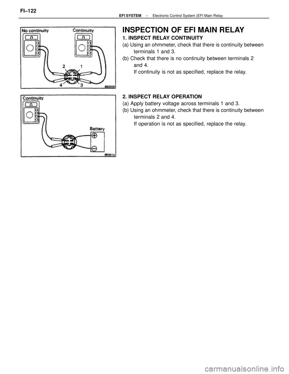
INSPECTION OF EFI MAIN RELAY
1. INSPECT RELAY CONTINUITY
(a) Using an ohmmeter, check that there is continuity between
terminals 1 and 3.
(b) Check that there is no continuity between terminals 2
and 4.
If continuity is not as specified, replace the relay.
2. INSPECT RELAY OPERATION
(a) Apply battery voltage across terminals 1 and 3.
(b) Using an ohmmeter, check that there is continuity between
terminals 2 and 4.
If operation is not as specified, replace the relay.
± EFI SYSTEMElectronic Control System (EFI Main RelayFI±122
Page 1137 of 2389
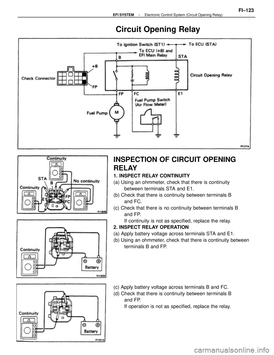
INSPECTION OF CIRCUIT OPENING
RELAY
1. INSPECT RELAY CONTINUITY
(a) Using an ohmmeter, check that there is continuity
between terminals STA and E1.
(b) Check that there is continuity between terminals B
and FC.
(c) Check that there is no continuity between terminals B
and FP.
If continuity is not as specified, replace the relay.
2. INSPECT RELAY OPERATION
(a) Apply battery voltage across terminals STA and E1.
(b) Using an ohmmeter, check that there is continuity between
terminals B and FP.
(c) Apply battery voltage across terminals B and FC.
(d) Check that there is continuity between terminals B
and FP.
If operation is not as specified, replace the relay.
Circuit Opening Relay
± EFI SYSTEMElectronic Control System (Circuit Opening Relay)FI±123
Page 1286 of 2389
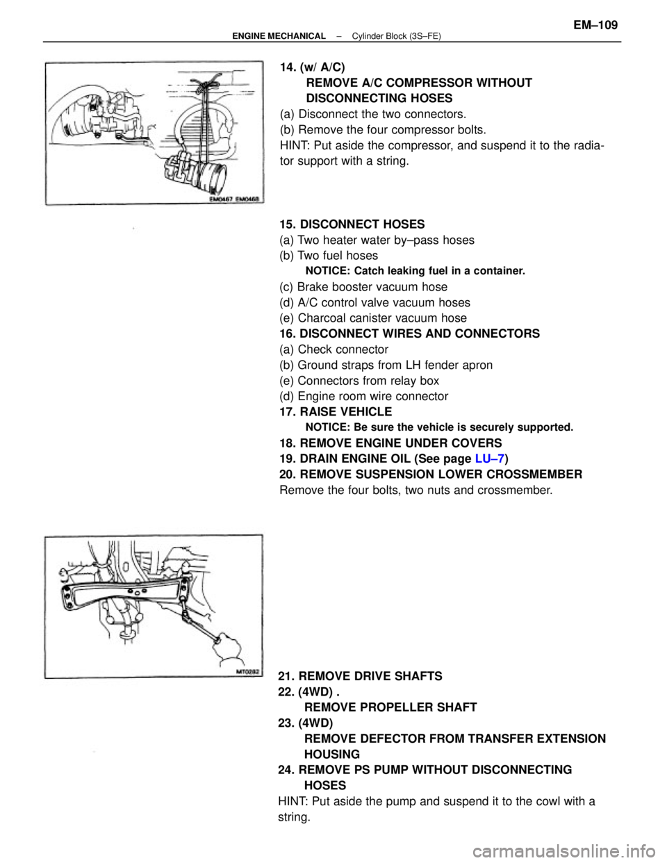
15. DISCONNECT HOSES
(a) Two heater water by±pass hoses
(b) Two fuel hoses
NOTICE: Catch leaking fuel in a container.
(c) Brake booster vacuum hose
(d) A/C control valve vacuum hoses
(e) Charcoal canister vacuum hose
16. DISCONNECT WIRES AND CONNECTORS
(a) Check connector
(b) Ground straps from LH fender apron
(e) Connectors from relay box
(d) Engine room wire connector
17. RAISE VEHICLE
NOTICE: Be sure the vehicle is securely supported.
18. REMOVE ENGINE UNDER COVERS
19. DRAIN ENGINE OIL (See page LU±7)
20. REMOVE SUSPENSION LOWER CROSSMEMBER
Remove the four bolts, two nuts and crossmember.
21. REMOVE DRIVE SHAFTS
22. (4WD) .
REMOVE PROPELLER SHAFT
23. (4WD)
REMOVE DEFECTOR FROM TRANSFER EXTENSION
HOUSING
24. REMOVE PS PUMP WITHOUT DISCONNECTING
HOSES
HINT: Put aside the pump and suspend it to the cowl with a
string.14. (w/ A/C)
REMOVE A/C COMPRESSOR WITHOUT
DISCONNECTING HOSES
(a) Disconnect the two connectors.
(b) Remove the four compressor bolts.
HINT: Put aside the compressor, and suspend it to the radia-
tor support with a string.
± ENGINE MECHANICALCylinder Block (3S±FE)EM±109
Page 1287 of 2389
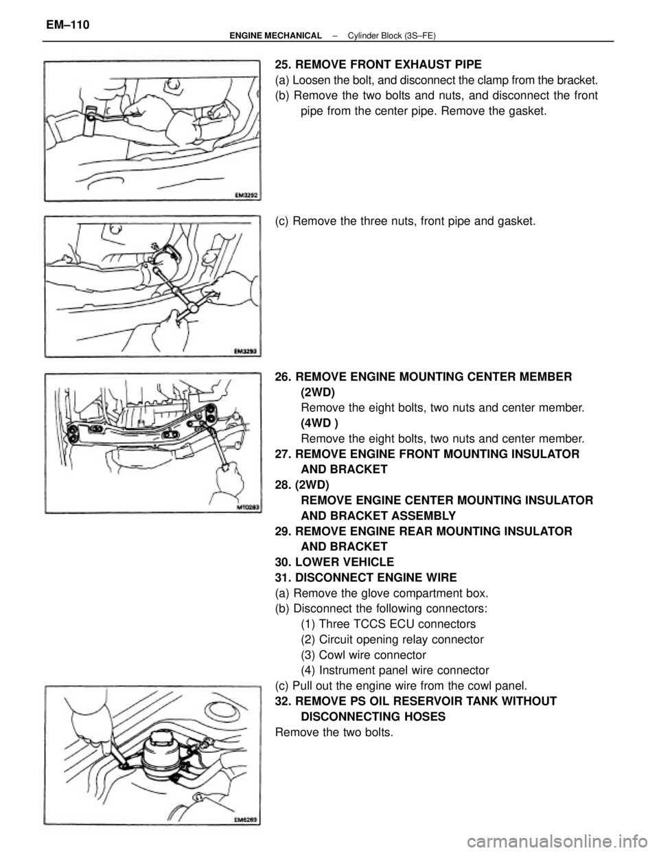
26. REMOVE ENGINE MOUNTING CENTER MEMBER
(2WD)
Remove the eight bolts, two nuts and center member.
(4WD )
Remove the eight bolts, two nuts and center member.
27. REMOVE ENGINE FRONT MOUNTING INSULATOR
AND BRACKET
28. (2WD)
REMOVE ENGINE CENTER MOUNTING INSULATOR
AND BRACKET ASSEMBLY
29. REMOVE ENGINE REAR MOUNTING INSULATOR
AND BRACKET
30. LOWER VEHICLE
31. DISCONNECT ENGINE WIRE
(a) Remove the glove compartment box.
(b) Disconnect the following connectors:
(1) Three TCCS ECU connectors
(2) Circuit opening relay connector
(3) Cowl wire connector
(4) Instrument panel wire connector
(c) Pull out the engine wire from the cowl panel.
32. REMOVE PS OIL RESERVOIR TANK WITHOUT
DISCONNECTING HOSES
Remove the two bolts. 25. REMOVE FRONT EXHAUST PIPE
(a) Loosen the bolt, and disconnect the clamp from the bracket.
(b) Remove the two bolts and nuts, and disconnect the front
pipe from the center pipe. Remove the gasket.
(c) Remove the three nuts, front pipe and gasket.
± ENGINE MECHANICALCylinder Block (3S±FE)EM±110
Page 1311 of 2389
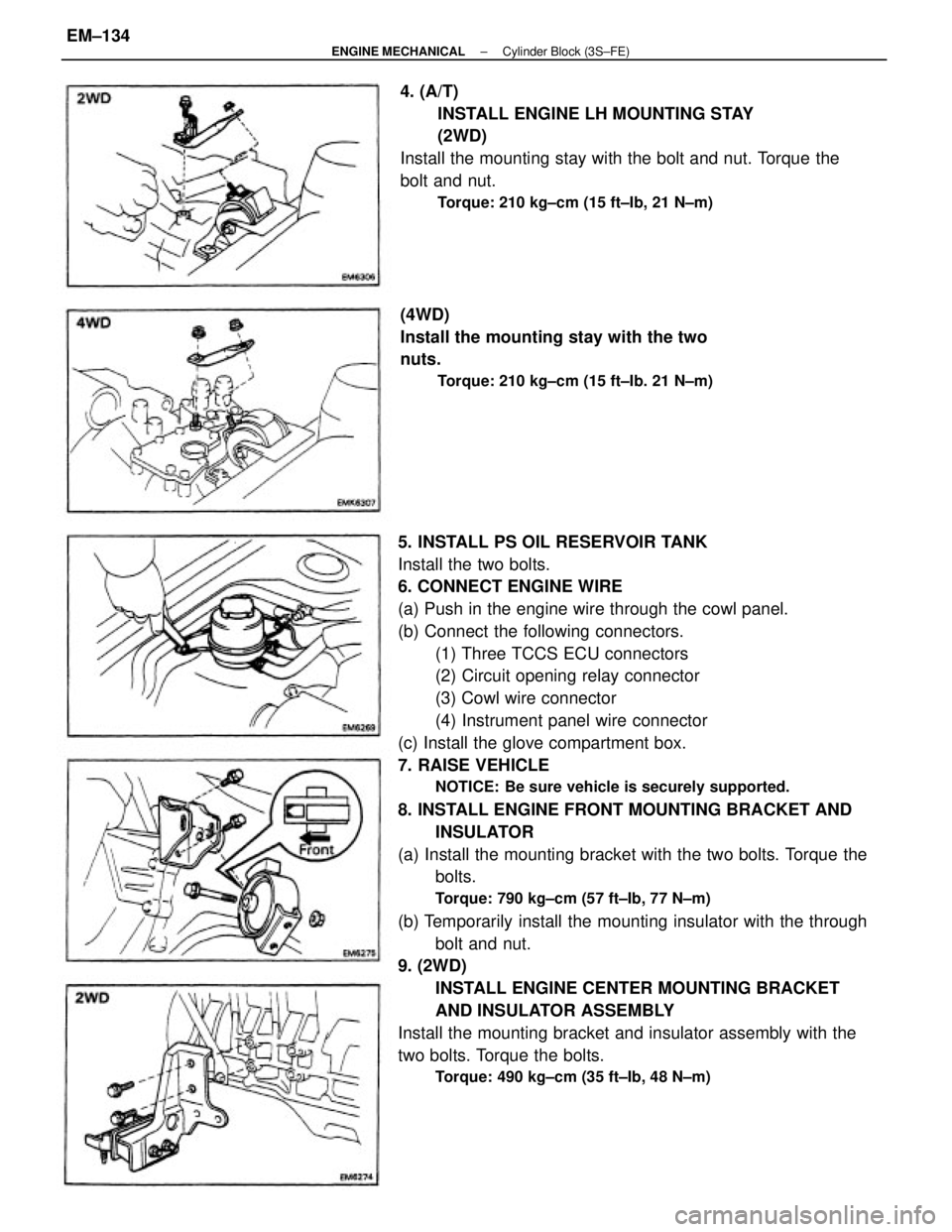
5. INSTALL PS OIL RESERVOIR TANK
Install the two bolts.
6. CONNECT ENGINE WIRE
(a) Push in the engine wire through the cowl panel.
(b) Connect the following connectors.
(1) Three TCCS ECU connectors
(2) Circuit opening relay connector
(3) Cowl wire connector
(4) Instrument panel wire connector
(c) Install the glove compartment box.
7. RAISE VEHICLE
NOTICE: Be sure vehicle is securely supported.
8. INSTALL ENGINE FRONT MOUNTING BRACKET AND
INSULATOR
(a) Install the mounting bracket with the two bolts. Torque the
bolts.
Torque: 790 kg±cm (57 ft±Ib, 77 N±m)
(b) Temporarily install the mounting insulator with the through
bolt and nut.
9. (2WD)
INSTALL ENGINE CENTER MOUNTING BRACKET
AND INSULATOR ASSEMBLY
Install the mounting bracket and insulator assembly with the
two bolts. Torque the bolts.
Torque: 490 kg±cm (35 ft±Ib, 48 N±m)
4. (A/T)
INSTALL ENGINE LH MOUNTING STAY
(2WD)
Install the mounting stay with the bolt and nut. Torque the
bolt and nut.
Torque: 210 kg±cm (15 ft±Ib, 21 N±m)
(4WD)
Install the mounting stay with the two
nuts.
Torque: 210 kg±cm (15 ft±Ib. 21 N±m)
± ENGINE MECHANICALCylinder Block (3S±FE)EM±134
Page 1313 of 2389
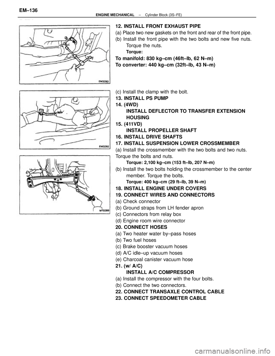
(c) Install the clamp with the bolt.
13. INSTALL PS PUMP
14. (4WD)
INSTALL DEFLECTOR TO TRANSFER EXTENSION
HOUSING
15. (411VD)
INSTALL PROPELLER SHAFT
16. INSTALL DRIVE SHAFTS
17. INSTALL SUSPENSION LOWER CROSSMEMBER
(a) Install the crossmember with the two bolts and two nuts.
Torque the bolts and nuts.
Torque: 2,100 kg±cm (153 ft±lb, 207 N±m)
(b) Install the two bolts holding the crossmember to the center
member. Torque the bolts.
Torque: 400 kg±cm (29 ft±Ib, 39 N±m)
18. INSTALL ENGINE UNDER COVERS
19. CONNECT WIRES AND CONNECTORS
(a) Check connector
(b) Ground straps from LH fender apron
(c) Connectors from relay box
(d) Engine room wire connector
20. CONNECT HOSES
(a) Two heater water by±pass hoses
(b) Two fuel hoses
(c) Brake booster vacuum hoses
(d) A/C idle±up vacuum hoses
(e) Charcoal canister vacuum hose
21. (w/ A/C)
INSTALL A/C COMPRESSOR
(a) Install the compressor with the four bolts.
(b) Connect the two connectors.
22. CONNECT TRANSAXLE CONTROL CABLE
23. CONNECT SPEEDOMETER CABLE 12. INSTALL FRONT EXHAUST PIPE
(a) Place two new gaskets on the front and rear of the front pipe.
(b) Install the front pipe with the two bolts and new five nuts.
Torque the nuts.
Torque:
To manifold: 830 kg±cm (46ft±Ib, 62 N±m)
To converter: 440 kg±cm (32ft±lb, 43 N±m)
± ENGINE MECHANICALCylinder Block (3S±FE)EM±136
Page 1318 of 2389
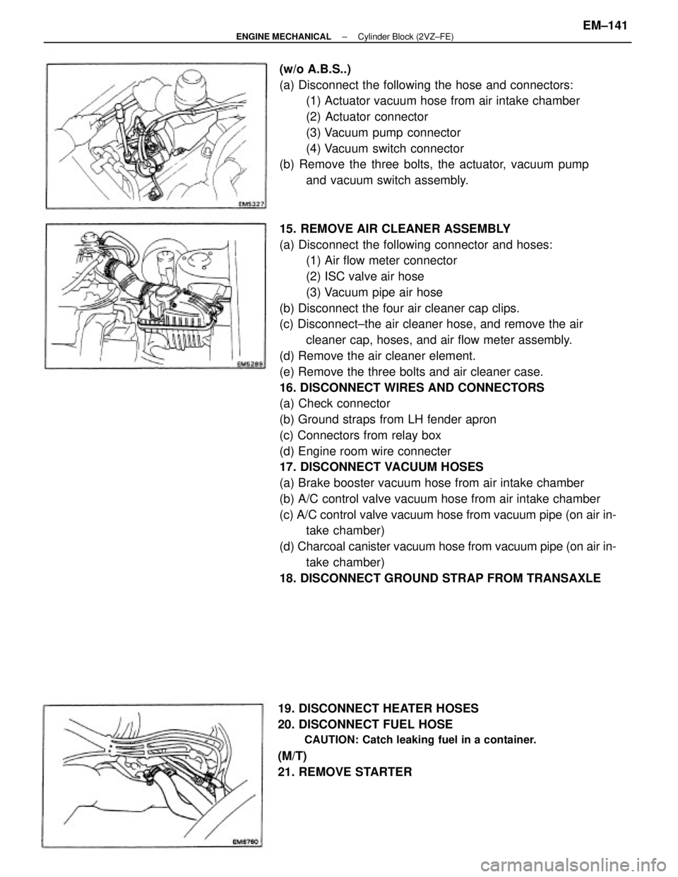
15. REMOVE AIR CLEANER ASSEMBLY
(a) Disconnect the following connector and hoses:
(1) Air flow meter connector
(2) ISC valve air hose
(3) Vacuum pipe air hose
(b) Disconnect the four air cleaner cap clips.
(c) Disconnect±the air cleaner hose, and remove the air
cleaner cap, hoses, and air flow meter assembly.
(d) Remove the air cleaner element.
(e) Remove the three bolts and air cleaner case.
16. DISCONNECT WIRES AND CONNECTORS
(a) Check connector
(b) Ground straps from LH fender apron
(c) Connectors from relay box
(d) Engine room wire connecter
17. DISCONNECT VACUUM HOSES
(a) Brake booster vacuum hose from air intake chamber
(b) A/C control valve vacuum hose from air intake chamber
(c) A/C control valve vacuum hose from vacuum pipe (on air in-
take chamber)
(d) Charcoal canister vacuum hose from vacuum pipe (on air in-
take chamber)
18. DISCONNECT GROUND STRAP FROM TRANSAXLE (w/o A.B.S..)
(a) Disconnect the following the hose and connectors:
(1) Actuator vacuum hose from air intake chamber
(2) Actuator connector
(3) Vacuum pump connector
(4) Vacuum switch connector
(b) Remove the three bolts, the actuator, vacuum pump
and vacuum switch assembly.
19. DISCONNECT HEATER HOSES
20. DISCONNECT FUEL HOSE
CAUTION: Catch leaking fuel in a container.
(M/T)
21. REMOVE STARTER
± ENGINE MECHANICALCylinder Block (2VZ±FE)EM±141