relay TOYOTA CAMRY V20 1986 Service Information
[x] Cancel search | Manufacturer: TOYOTA, Model Year: 1986, Model line: CAMRY V20, Model: TOYOTA CAMRY V20 1986Pages: 2389, PDF Size: 84.44 MB
Page 242 of 2389
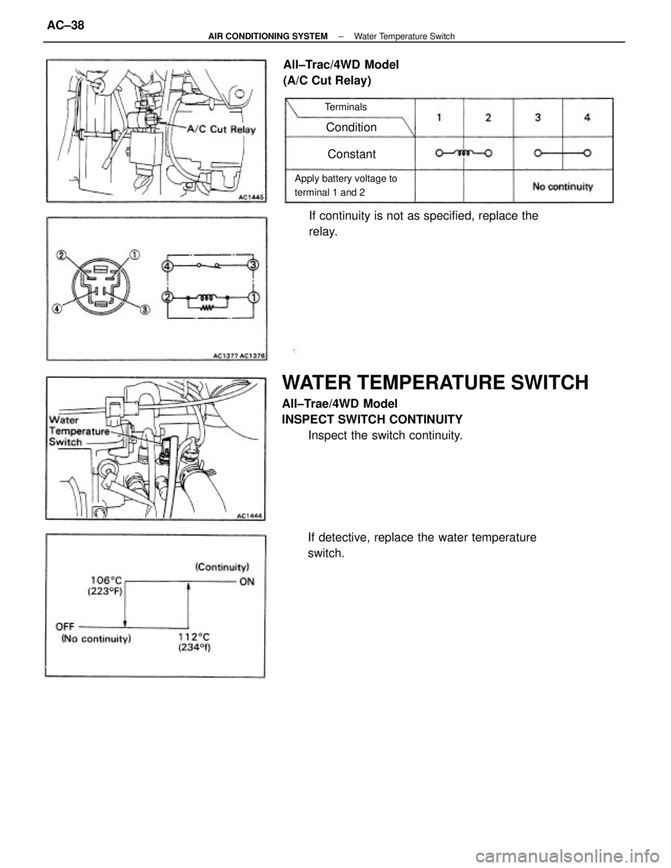
WATER TEMPERATURE SWITCH
All±Trae/4WD Model
INSPECT SWITCH CONTINUITY
Inspect the switch continuity.
If detective, replace the water temperature
switch.If continuity is not as specified, replace the
relay. All±Trac/4WD Model
(A/C Cut Relay)
Apply battery voltage to
terminal 1 and 2Terminals
Condition
Constant
± AIR CONDITIONING SYSTEMWater Temperature SwitchAC±38
Page 244 of 2389
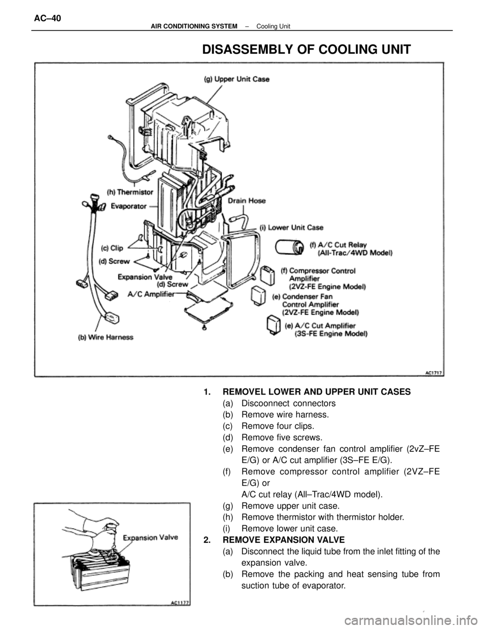
1. REMOVEL LOWER AND UPPER UNIT CASES
(a) Discoonnect connectors
(b) Remove wire harness.
(c) Remove four clips.
(d) Remove five screws.
(e) Remove condenser fan control amplifier (2vZ±FE
E/G) or A/C cut amplifier (3S±FE E/G).
(f) Remove compressor control amplifier (2VZ±FE
E/G) or
A/C cut relay (All±Trac/4WD model).
(g) Remove upper unit case.
(h) Remove thermistor with thermistor holder.
(i) Remove lower unit case.
2. REMOVE EXPANSION VALVE
(a) Disconnect the liquid tube from the inlet fitting of the
expansion valve.
(b) Remove the packing and heat sensing tube from
suction tube of evaporator.
DISASSEMBLY OF COOLING UNIT
± AIR CONDITIONING SYSTEMCooling UnitAC±40
Page 298 of 2389
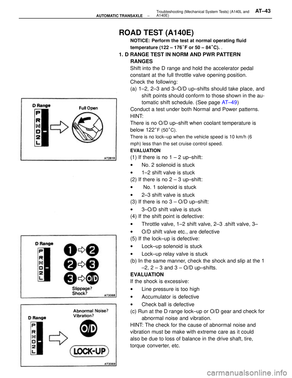
ROAD TEST (A140E)
NOTICE: Perform the test at normal operating fluid
temperature (122 ± 176°F or 50 ± 84°C). .
1. D RANGE TEST IN NORM AND PWR PATTERN
RANGES
Shift into the D range and hold the accelerator pedal
constant at the full throttle valve opening position.
Check the following:
(a) 1±2, 2±3 and 3±O/D up±shifts should take place, and
shift points should conform to those shown in the au-
tomatic shift schedule. (See page AT±49)
Conduct a test under both Normal and Power patterns.
HINT:
There is no O/D up±shift when coolant temperature is
below 122
°F (50°C).
There is no lock±up when the vehicle speed is 10 km/h (6
mph) less than the set cruise control speed.
EVALUATION
(1) If there is no 1 ± 2 up±shift:
wNo. 2 solenoid is stuck
w1±2 shift valve is stuck
(2) If there is no 2 ± 3 up±shift:
w No. 1 solenoid is stuck
w2±3 shift valve is stuck
(3) If there is no 3 ± O/D up±shift:
w3±O/D shift valve is stuck
(4) If the shift point is defective:
wThrottle valve, 1±2 shift valve, 2±3 .shift valve, 3±
wO/D shift valve etc., are defective
(5) If the lock±up is defective:
wLock±up solenoid is stuck
wLock±up relay valve is stuck
(b) In the same manner, check the shock and slip at the 1
±2, 2 ± 3 and 3 ± O/D up±shifts.
EVALUATION
If the shock is excessive:
wLine pressure is too high
wAccumulator is defective
wCheck ball is defective
(c) Run at the D range lock±up or O/D gear and check for
abnormal noise and vibration.
HINT: The check for the cause of abnormal noise and
vibration must be make with extreme care as it could
also be due to loss of balance in the drive shaft, tire,
torque converter, etc.
± AUTOMATIC TRANSAXLETroubleshooting (Mechanical System Tests) (A140L and
A140E)AT±43
Page 380 of 2389
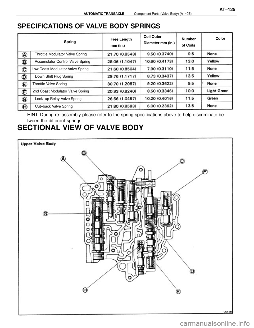
HINT: During re±assembly please refer to the spring specifications above to help discriminate be-
tween the different springs.
SECTIONAL VIEW OF VALVE BODY
SPECIFICATIONS OF VALVE BODY SPRINGS
Low Coast Modulator Valve Spring
2nd Coast Modulator Valve SpringAccumulator Control Valve SpringThrottle Modulator Valve Spring
Lock±up Relay Valve SpringCoil Outer
Diameter mm (in.)
Down Shift Plug Spring
Cut±back Valve Spring Throttle Valve SpringFree Length
mm (in.)Number
of Coils SpringColor
± AUTOMATIC TRANSAXLEComponent Parts (Valve Body) (A140E)AT±125
Page 392 of 2389
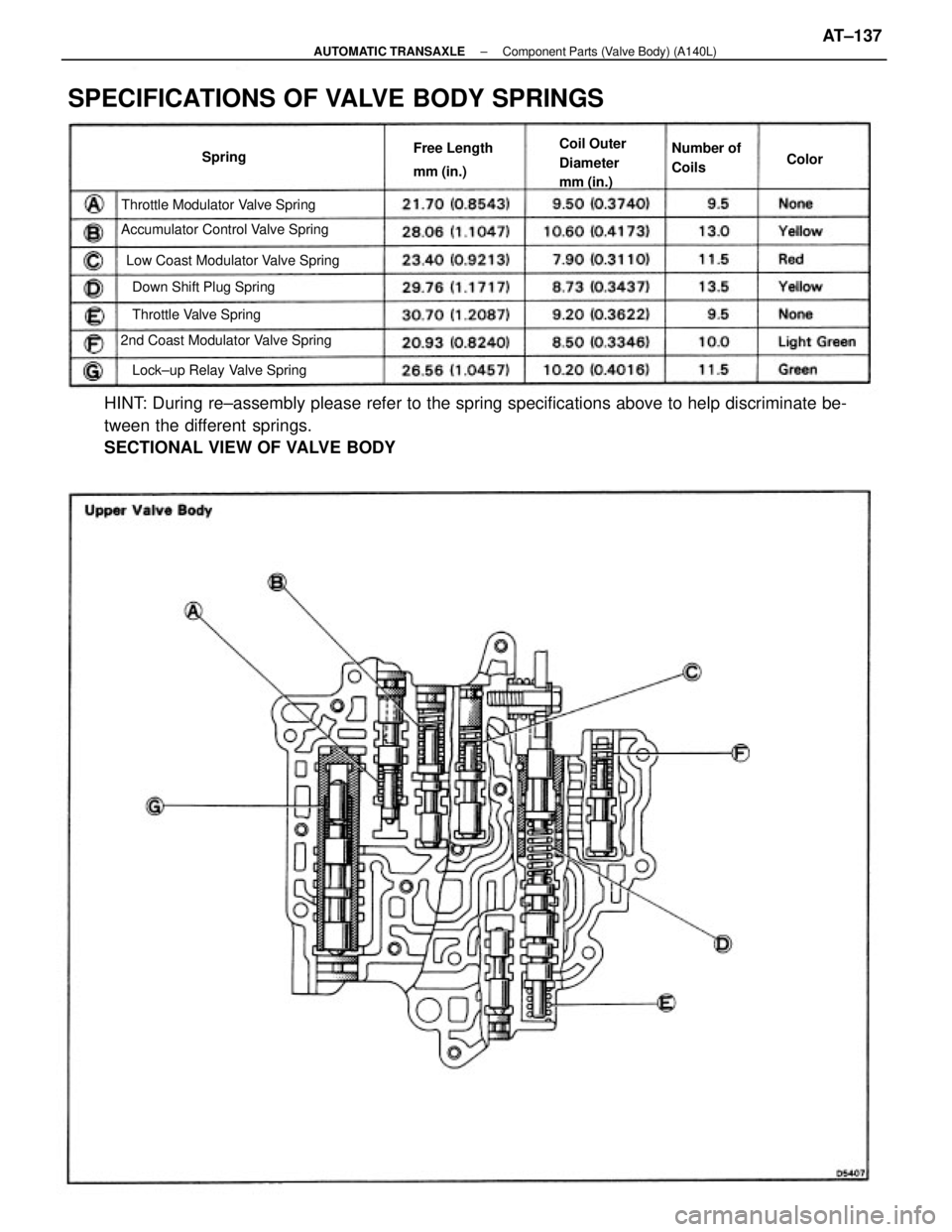
HINT: During re±assembly please refer to the spring specifications above to help discriminate be-
tween the different springs.
SECTIONAL VIEW OF VALVE BODY
SPECIFICATIONS OF VALVE BODY SPRINGS
Low Coast Modulator Valve Spring
2nd Coast Modulator Valve SpringAccumulator Control Valve SpringThrottle Modulator Valve Spring
Lock±up Relay Valve SpringCoil Outer
Diameter
mm (in.)
Down Shift Plug Spring
Throttle Valve SpringFree Length
mm (in.)Number of
Coils Spring
Color
± AUTOMATIC TRANSAXLEComponent Parts (Valve Body) (A140L)AT±137
Page 463 of 2389
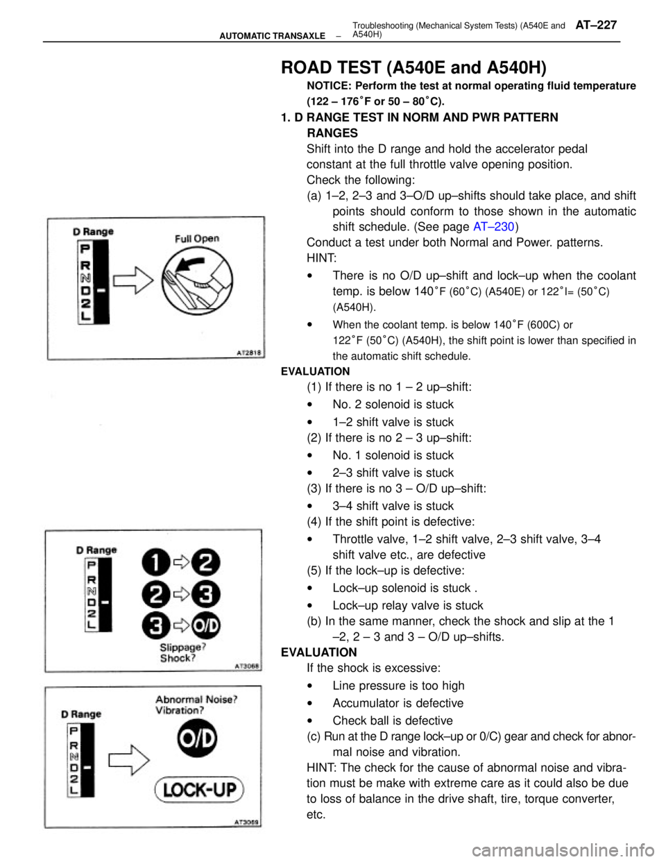
ROAD TEST (A540E and A540H)
NOTICE: Perform the test at normal operating fluid temperature
(122 ± 176°F or 50 ± 80°C).
1. D RANGE TEST IN NORM AND PWR PATTERN
RANGES
Shift into the D range and hold the accelerator pedal
constant at the full throttle valve opening position.
Check the following:
(a) 1±2, 2±3 and 3±O/D up±shifts should take place, and shift
points should conform to those shown in the automatic
shift schedule. (See page AT±230)
Conduct a test under both Normal and Power. patterns.
HINT:
wThere is no O/D up±shift and lock±up when the coolant
temp. is below 140
°F (60°C) (A540E) or 122°I= (50°C)
(A540H).
wWhen the coolant temp. is below 140°F (600C) or
122°F (50°C) (A540H), the shift point is lower than specified in
the automatic shift schedule.
EVALUATION
(1) If there is no 1 ± 2 up±shift:
wNo. 2 solenoid is stuck
w1±2 shift valve is stuck
(2) If there is no 2 ± 3 up±shift:
wNo. 1 solenoid is stuck
w2±3 shift valve is stuck
(3) If there is no 3 ± O/D up±shift:
w3±4 shift valve is stuck
(4) If the shift point is defective:
wThrottle valve, 1±2 shift valve, 2±3 shift valve, 3±4
shift valve etc., are defective
(5) If the lock±up is defective:
wLock±up solenoid is stuck .
wLock±up relay valve is stuck
(b) In the same manner, check the shock and slip at the 1
±2, 2 ± 3 and 3 ± O/D up±shifts.
EVALUATION
If the shock is excessive:
wLine pressure is too high
wAccumulator is defective
wCheck ball is defective
(c) Run at the D range lock±up or 0/C) gear and check for abnor-
mal noise and vibration.
HINT: The check for the cause of abnormal noise and vibra-
tion must be make with extreme care as it could also be due
to loss of balance in the drive shaft, tire, torque converter,
etc.
± AUTOMATIC TRANSAXLETroubleshooting (Mechanical System Tests) (A540E and
A540H)AT±227
Page 571 of 2389
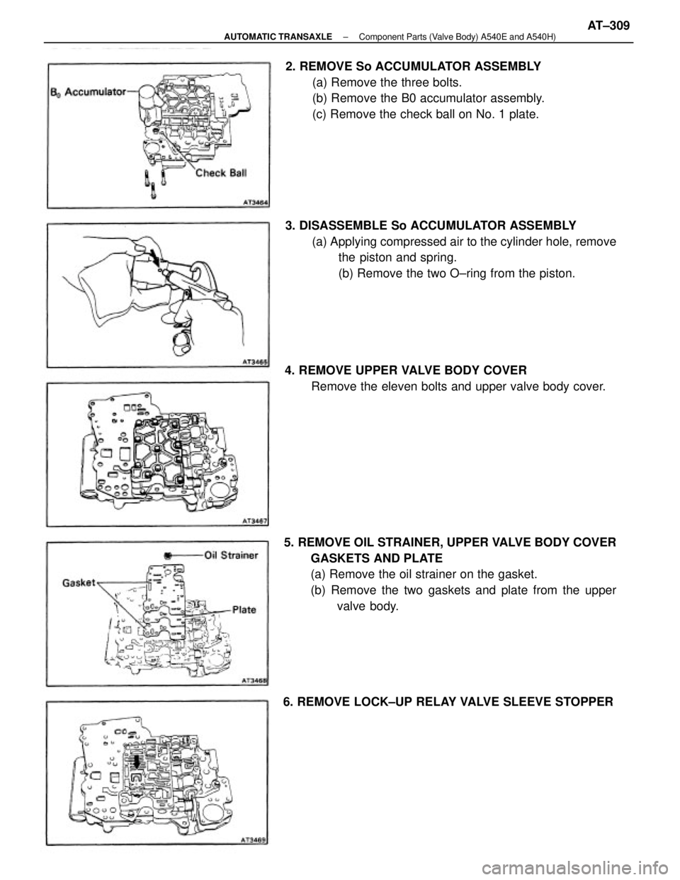
5. REMOVE OIL STRAINER, UPPER VALVE BODY COVER
GASKETS AND PLATE
(a) Remove the oil strainer on the gasket.
(b) Remove the two gaskets and plate from the upper
valve body. 3. DISASSEMBLE So ACCUMULATOR ASSEMBLY
(a) Applying compressed air to the cylinder hole, remove
the piston and spring.
(b) Remove the two O±ring from the piston. 2. REMOVE So ACCUMULATOR ASSEMBLY
(a) Remove the three bolts.
(b) Remove the B0 accumulator assembly.
(c) Remove the check ball on No. 1 plate.
4. REMOVE UPPER VALVE BODY COVER
Remove the eleven bolts and upper valve body cover.
6. REMOVE LOCK±UP RELAY VALVE SLEEVE STOPPER
± AUTOMATIC TRANSAXLEComponent Parts (Valve Body) A540E and A540H)AT±309
Page 575 of 2389
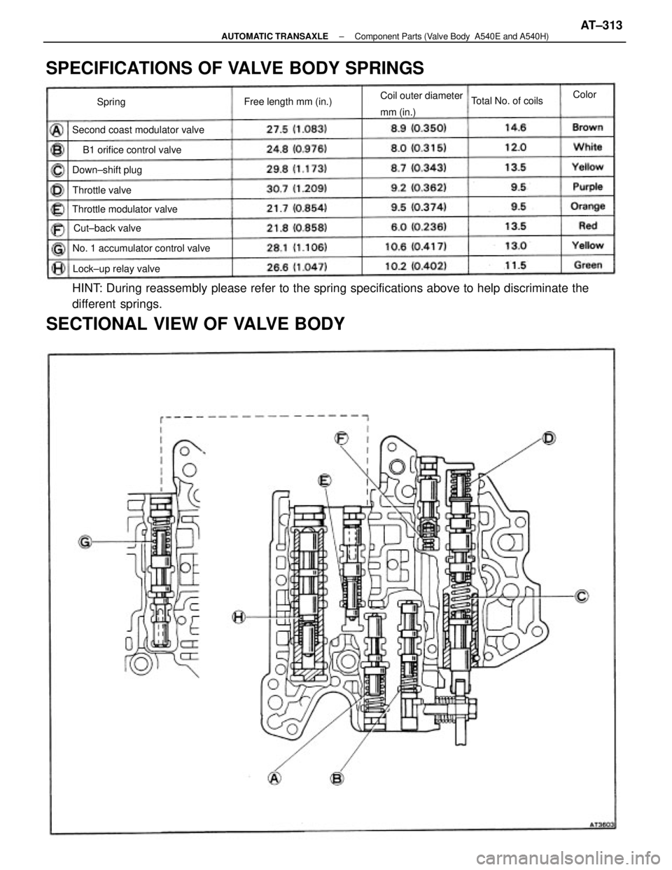
HINT: During reassembly please refer to the spring specifications above to help discriminate the
different springs.
SECTIONAL VIEW OF VALVE BODY SPECIFICATIONS OF VALVE BODY SPRINGS
No. 1 accumulator control valveCoil outer diameter
mm (in.)
Second coast modulator valve
B1 orifice control valve
Throttle modulator valveFree length mm (in.)
Lock±up relay valveTotal No. of coils
Down±shift plug
Cut±back valve Throttle valveColor
Spring
± AUTOMATIC TRANSAXLEComponent Parts (Valve Body A540E and A540H)AT±313
Page 581 of 2389
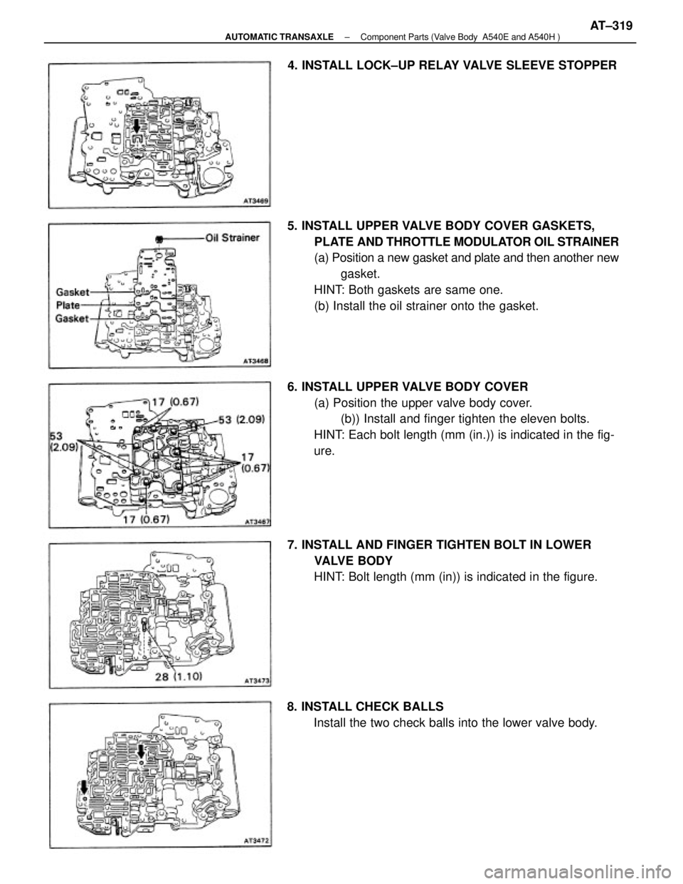
5. INSTALL UPPER VALVE BODY COVER GASKETS,
PLATE AND THROTTLE MODULATOR OIL STRAINER
(a) Position a new gasket and plate and then another new
gasket.
HINT: Both gaskets are same one.
(b) Install the oil strainer onto the gasket.
6. INSTALL UPPER VALVE BODY COVER
(a) Position the upper valve body cover.
(b)) Install and finger tighten the eleven bolts.
HINT: Each bolt length (mm (in.)) is indicated in the fig-
ure.
7. INSTALL AND FINGER TIGHTEN BOLT IN LOWER
VALVE BODY
HINT: Bolt length (mm (in)) is indicated in the figure.
8. INSTALL CHECK BALLS
Install the two check balls into the lower valve body. 4. INSTALL LOCK±UP RELAY VALVE SLEEVE STOPPER
± AUTOMATIC TRANSAXLEComponent Parts (Valve Body A540E and A540H )AT±319
Page 751 of 2389
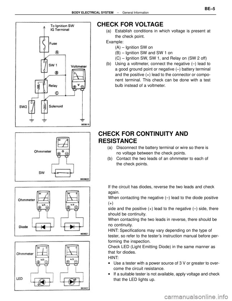
If the circuit has diodes, reverse the two leads and check
again.
When contacting the negative (±) lead to the diode positive
(+)
side and the positive (+) lead to the negative (±) side, there
should be continuity.
When contacting the two leads in reverse, there should be
no continuity.
HINT: Specifications may vary depending on the type of
tester, so refer to the tester's instruction manual before per-
forming the inspection.
Check LED (Light Emitting Diode) in the same manner as
that for diodes.
HINT:
wUse a tester with a power source of 3 V or greater to over-
come the circuit resistance.
wIf a suitable tester is not available, apply voltage and check
that the LED lights up.
CHECK FOR VOLTAGE
(a) Establish conditions in which voltage is present at
the check point.
Example:
(A) ± Ignition SW on
(B) ± Ignition SW and SW 1 on
(C) ± Ignition SW, SW 1, and Relay on (SW 2 off)
(b) Using a voltmeter, connect the negative (±) lead to
a good ground point or negative (±) battery terminal
and the positive (+) lead to the connector or compo-
nent terminal. This check can be done with a test
bulb instead of a voltmeter.
CHECK FOR CONTINUITY AND
RESISTANCE
(a) Disconnect the battery terminal or wire so there is
no voltage between the check points.
(b) Contact the two leads of an ohmmeter to each of
the check points.
± BODY ELECTRICAL SYSTEMGeneral InformationBE±5