check engine TOYOTA CAMRY V20 1986 Service Information
[x] Cancel search | Manufacturer: TOYOTA, Model Year: 1986, Model line: CAMRY V20, Model: TOYOTA CAMRY V20 1986Pages: 2389, PDF Size: 84.44 MB
Page 1872 of 2389
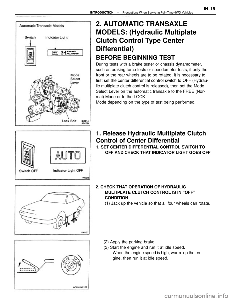
2. AUTOMATIC TRANSAXLE
MODELS: (Hydraulic Multiplate
Clutch Control Type Center
Differential)
BEFORE BEGINNING TEST
During tests with a brake tester or chassis dynamometer,
such as braking force tests or speedometer tests, if only the
front or the rear wheels are to be rotated, it is necessary to
first set the center differential control switch to OFF (Hydrau-
lic multiplate clutch control is released), then set the Mode
Select Lever on the automatic transaxle to the FREE (Nor-
mal) Mode or to the LOCK
Mode depending on the type of test being performed.
1. Release Hydraulic Multiplate Clutch
Control of Center Differential
1. SET CENTER DIFFERENTIAL CONTROL SWITCH TO
OFF AND CHECK THAT INDICATOR LIGHT GOES OFF
2. CHECK THAT OPERATION OF HYDRAULIC
MULTIPLATE CLUTCH CONTROL IS IN ºOFFº
CONDITION
(1) Jack up the vehicle so that all four wheels can rotate.
(2) Apply the parking brake.
(3) Start the engine and run it at idle speed.
When the engine speed is high, warm±up the en-
gine, then run it at idle speed.
± INTRODUCTIONPrecautions When Servicing Full±Time 4WD VehiclesIN±15
Page 1873 of 2389
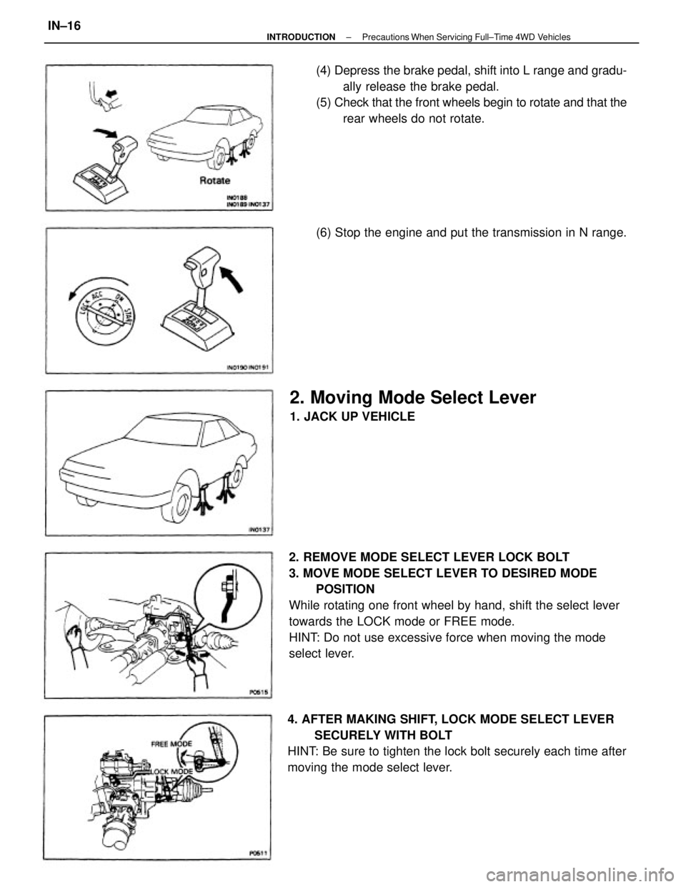
2. REMOVE MODE SELECT LEVER LOCK BOLT
3. MOVE MODE SELECT LEVER TO DESIRED MODE
POSITION
While rotating one front wheel by hand, shift the select lever
towards the LOCK mode or FREE mode.
HINT: Do not use excessive force when moving the mode
select lever.
4. AFTER MAKING SHIFT, LOCK MODE SELECT LEVER
SECURELY WITH BOLT
HINT: Be sure to tighten the lock bolt securely each time after
moving the mode select lever.(4) Depress the brake pedal, shift into L range and gradu-
ally release the brake pedal.
(5) Check that the front wheels begin to rotate and that the
rear wheels do not rotate.
2. Moving Mode Select Lever
1. JACK UP VEHICLE(6) Stop the engine and put the transmission in N range.
± INTRODUCTIONPrecautions When Servicing Full±Time 4WD VehiclesIN±16
Page 1876 of 2389
![TOYOTA CAMRY V20 1986 Service Information TEST METHOD B (High Speed Test)
[Vehicle speed: Over 38 mph (60 km/h)]
1. SET CENTER DIFFERENTIAL CONTROL SWITCH TO
OFF
(1) Check that the center differential control indicator light
goes oft.
(2) Fur TOYOTA CAMRY V20 1986 Service Information TEST METHOD B (High Speed Test)
[Vehicle speed: Over 38 mph (60 km/h)]
1. SET CENTER DIFFERENTIAL CONTROL SWITCH TO
OFF
(1) Check that the center differential control indicator light
goes oft.
(2) Fur](/img/14/57449/w960_57449-1875.png)
TEST METHOD B (High Speed Test)
[Vehicle speed: Over 38 mph (60 km/h)]
1. SET CENTER DIFFERENTIAL CONTROL SWITCH TO
OFF
(1) Check that the center differential control indicator light
goes oft.
(2) Further check that the operation of the hydraulic multi-
plate clutch control of the center differential is in
OFF condition.
(See page IN±15)
2. MOVE MODE SELECT LEVER ON TRANSAXLE TO ºLOCKº
MODE AND LOCK IT SECURELY WITH BOLT
(See page IN±16)
3. CONFIRM MODE SELECTION
(See page IN±17) 7. OPERATE TESTER ROLLERS AND MEASURE
BRAKING FORCE WITH ENGINE AT IDLE
HINT: Since different types of tester are used, such as spe-
cialized brake testers and combination testers with built in
chassis dynamometer, speedometer tester, brake tester, etc.,
conduct the test in accordance with the instructions furnished
for the tester model used.
4. REMOVE REAR PROPELLER SHAFT
Make matching marks on each end of the propeller shaft,
then remove it.8. AFTER FINISHING TEST, RETURN CENTER
DIFFERENTIAL CONTROL SWITCH TO ºAUTOº AND
CHECK THAT INDICATOR LIGHT GOES ON
± INTRODUCTIONPrecautions When Servicing Full±Time 4WD VehiclesIN±19
Page 1878 of 2389
![TOYOTA CAMRY V20 1986 Service Information SPEEDOMETER TEST OR OTHER TESTS
[Using Speedometer Tester or Chassis Dynamometer]
1. SET CENTER DIFFERENTIAL CONTROL SWITCH TO
OFF
(1) Check that the center differential control indicator light
goes TOYOTA CAMRY V20 1986 Service Information SPEEDOMETER TEST OR OTHER TESTS
[Using Speedometer Tester or Chassis Dynamometer]
1. SET CENTER DIFFERENTIAL CONTROL SWITCH TO
OFF
(1) Check that the center differential control indicator light
goes](/img/14/57449/w960_57449-1877.png)
SPEEDOMETER TEST OR OTHER TESTS
[Using Speedometer Tester or Chassis Dynamometer]
1. SET CENTER DIFFERENTIAL CONTROL SWITCH TO
OFF
(1) Check that the center differential control indicator light
goes oft.
(2) Further check that the operation of the hydraulic
multiplate clutch control of the center differential is in
OFF condition.
(See page IN±15)
2. MOVE MODE SELECT LEVER ON TRANSAXLE TO ºLOCKº
MODE AND LOCK IT SECURELY WITH BOLT (See page
IN±16)
3. CONFIRM MODE SELECTION
(See page IN±17)
8. DISCONNECT INERTIA WEIGHT FROM TESTER ROLL-
ER (If equipped with it)
9. TEST VEHICLE
(1) Start the engine.
(2) Put the transmission in D range, then gradually in-
crease the speed as the test in conducted.
(3) After the test is finished, reduce the speed gradually
and stop the engine. 4. REMOVE REAR PROPELLER SHAFT
Make matching marks on each end of the rear propeller
shaft, then remove it.
5. PLACE FRONT WHEELS ON TESTER ROLLERS
6. CHOCK REAR WHEELS
7. APPLY PARKING BRAKE
10. AFTER FINISHING TEST, INSTALL REAR PROPELLER
SHAFT
Align the matching marks made on the rear propeller shaft
before removal, then install it.
± INTRODUCTIONPrecautions When Servicing Full±Time 4WD VehiclesIN±21
Page 1880 of 2389
ON±VEHICLE WHEEL BALANCING
NOTICE:
1. When doing on±vehicle wheel balancing on a fulltime 4WD
vehicle, to prevent the wheels from rotating at different
speeds or in different directions from each other (which
could lead to damage to the center differential or trans-
axle gears), always be sure to observe the following pre-
cautions:
(1) A11 four wheels should be jacked up, completely clear
of the ground.
(2) The wheels should be driven by both the engine and
the wheel balancer.
(3) The center differential control switch should be in the
OFF condition.
(4) The mode select lever on the transaxle should be in
the LOCK position.
(5) The parking brake lever should be fully released.
(6) None of the brakes should be allowed to drag.
2. Avoid sudden acceleration, deceleration and braking.
3. Carry out the wheel balancing with the transmission in D
range.
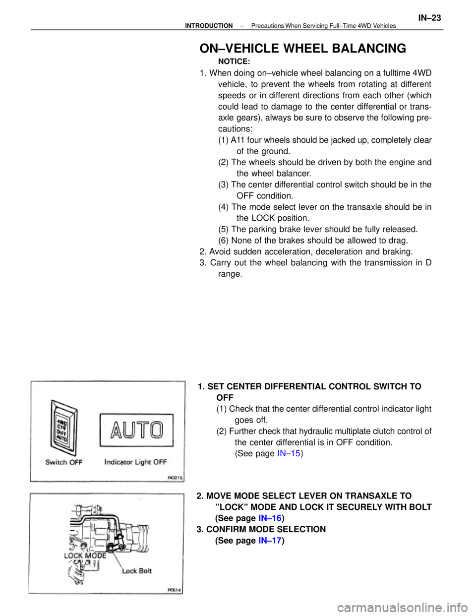
1. SET CENTER DIFFERENTIAL CONTROL SWITCH TO
OFF
(1) Check that the center differential control indicator light
goes off.
(2) Further check that hydraulic multiplate clutch control of
the center differential is in OFF condition.
(See page IN±15)
2. MOVE MODE SELECT LEVER ON TRANSAXLE TO
ºLOCKº MODE AND LOCK IT SECURELY WITH BOLT
(See page IN±16)
3. CONFIRM MODE SELECTION
(See page IN±17)
± INTRODUCTIONPrecautions When Servicing Full±Time 4WD VehiclesIN±23
Page 1882 of 2389
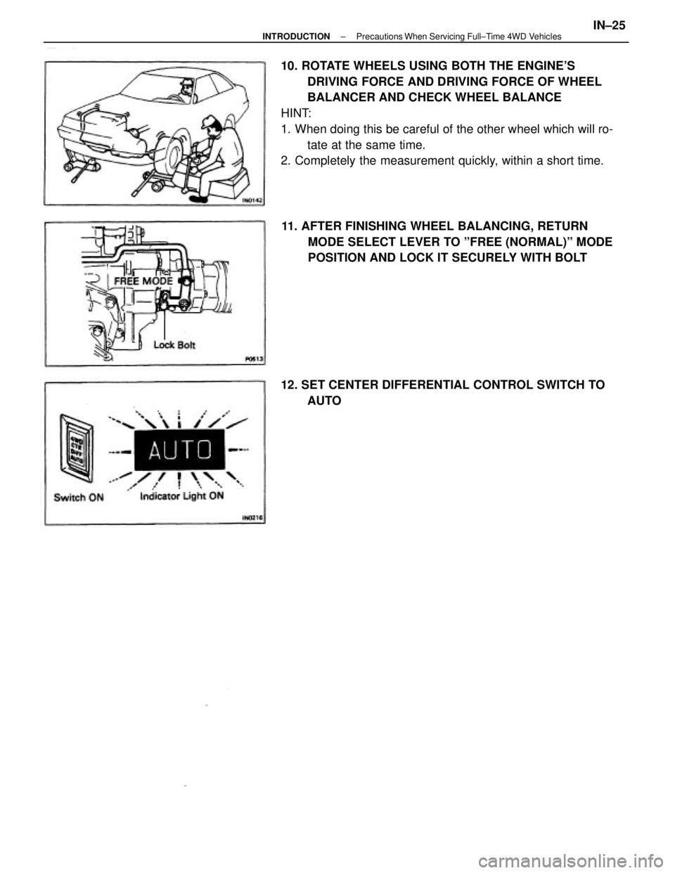
10. ROTATE WHEELS USING BOTH THE ENGINE'S
DRIVING FORCE AND DRIVING FORCE OF WHEEL
BALANCER AND CHECK WHEEL BALANCE
HINT:
1. When doing this be careful of the other wheel which will ro-
tate at the same time.
2. Completely the measurement quickly, within a short time.
11. AFTER FINISHING WHEEL BALANCING, RETURN
MODE SELECT LEVER TO ºFREE (NORMAL)º MODE
POSITION AND LOCK IT SECURELY WITH BOLT
12. SET CENTER DIFFERENTIAL CONTROL SWITCH TO
AUTO
± INTRODUCTIONPrecautions When Servicing Full±Time 4WD VehiclesIN±25
Page 1889 of 2389
A pressure feeding lubrication system has been adopted to supply oil to the moving parts of this engine.
The lubrication system consists of an oil pan, oil pump, oil filter and other external parts which supply oil
to the moving parts in the engine block The oil circuit is shown in the illustration at the top of the pre-
vious page. Oil from the oil pan is pumped up by the oil pump. After it passes through the oil filter, it is
fed through the various oil holes in the crankshaft and cylinder block. After passing through the cylinder
block and performing its lubricating function, the oil is returned by gravity to the oil pan. A dipstick on the
center left side of the cylinder block is provided to check the oil level.
OIL PUMP
The oil pump pumps up oil from the oil pan and sends it under pressure to the various parts of the en-
gine.
An oil strainer is mounted in front of the inlet to the oil pump. The oil pump itself is a trochoid±type
pump, inside of which is a drive rotor and a driven rotor. 'When the drive rotor rotates, the driven rotor
rotates in the same direction, and since the axis of the driven rotor shaft is different from the center of
the driven rotor, the space between the two rotors is changed as they rotate. Oil is drawn in when the
space is wide and is discharged when the space in narrow.
OIL PRESSURE REGULATOR (RELIEF VALVE)
At high engine speeds, the engine oil supplied by the oil pump exceeds the capacity of the engine to
utilize it.
For that reason, the oil pressure regulator works to prevent an oversupply of oil. During normal oil sup-
ply, a coil spring and valve keep the by±pass closed, but when too much oil is being fed, the pressure
become extremely high, overpowering the force of the spring and opening the valves. This allows the
excess oil to flow through the valve and return to the oil pan.
OIL FILTER
The oil filter is a full flow type filter with a built±in paper filter element, Particles of metal from wear, air-
born dirt, carbon and other impurities can get in the oil during use and could cause accelerated wear or
seizing if allowed to circulate through the engine. The oil filter, integrated into the oil line, removes these
impurities as the oil passes through it. The filter is mounted outside the engine to simplify replacement of
the filter element.
A relief valve is also included ahead of the filter element to relieve the high oil pressure in case the filter
element becomes clogged with impurities. The relief valve opens when the oil pressure overpowers the
force of the spring. Oil passing through the relief valve by±passes the oil filter and flows directly into the
main oil hole in the engine.
± LUBRICATION SYSTEMDescriptionLU±4
Page 1891 of 2389
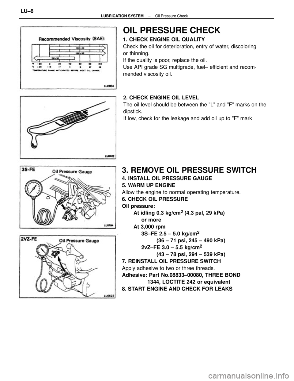
3. REMOVE OIL PRESSURE SWITCH
4. INSTALL OIL PRESSURE GAUGE
5. WARM UP ENGINE
Allow the engine to normal operating temperature.
6. CHECK OIL PRESSURE
Oil pressure:
At idling 0.3 kg/cm
2 (4.3 pal, 29 kPa)
or more
At 3,000 rpm
3S±FE 2.5 ± 5.0 kg/cm
2
(36 ± 71 psi, 245 ± 490 kPa)
2vZ±FE 3.0 ± 5.5 kg/cm
2
(43 ± 78 psi, 294 ± 539 kPa)
7. REINSTALL OIL PRESSURE SWITCH
Apply adhesive to two or three threads.
Adhesive: Part No.08833±00080, THREE BOND
1344, LOCTITE 242 or equivalent
8. START ENGINE AND CHECK FOR LEAKS
OIL PRESSURE CHECK
1. CHECK ENGINE OIL QUALITY
Check the oil for deterioration, entry of water, discoloring
or thinning.
If the quality is poor, replace the oil.
Use API grade SG multigrade, fuel± efficient and recom-
mended viscosity oil.
2. CHECK ENGINE OIL LEVEL
The oil level should be between the ºLº and ºFº marks on the
dipstick.
If low, check for the leakage and add oil up to ºFº mark
± LUBRICATION SYSTEMOil Pressure CheckLU±6
Page 1892 of 2389
REPLACEMENT OF ENGINE OIL
AND OIL FILTER
NOTICE:
wProlonged and repeated contact with mineral oil will re-
sult in the removal of natural¿¿ts from the skin, leading
to dryness, irritation and dermatitis. In addition, used en-
gine oil contains potentially harmful contaminants
which may cause skin cancer.
wCare should be taken, therefore, when changing engine
oil, to minimize the frequency and length of time your
skin is exposed to used engine oil. Protective clothing
and gloves, that cannot be penetrated by oil, should be
worn. The skin should be thoroughly washed with soap
and water, or use waterless hand cleaner, to remove any
used engine oil. Do not use gasoline, thinners, or sol-
vents.
wIn order to preserve the environment, used oil must be
disposed of only at designated disposal sites.
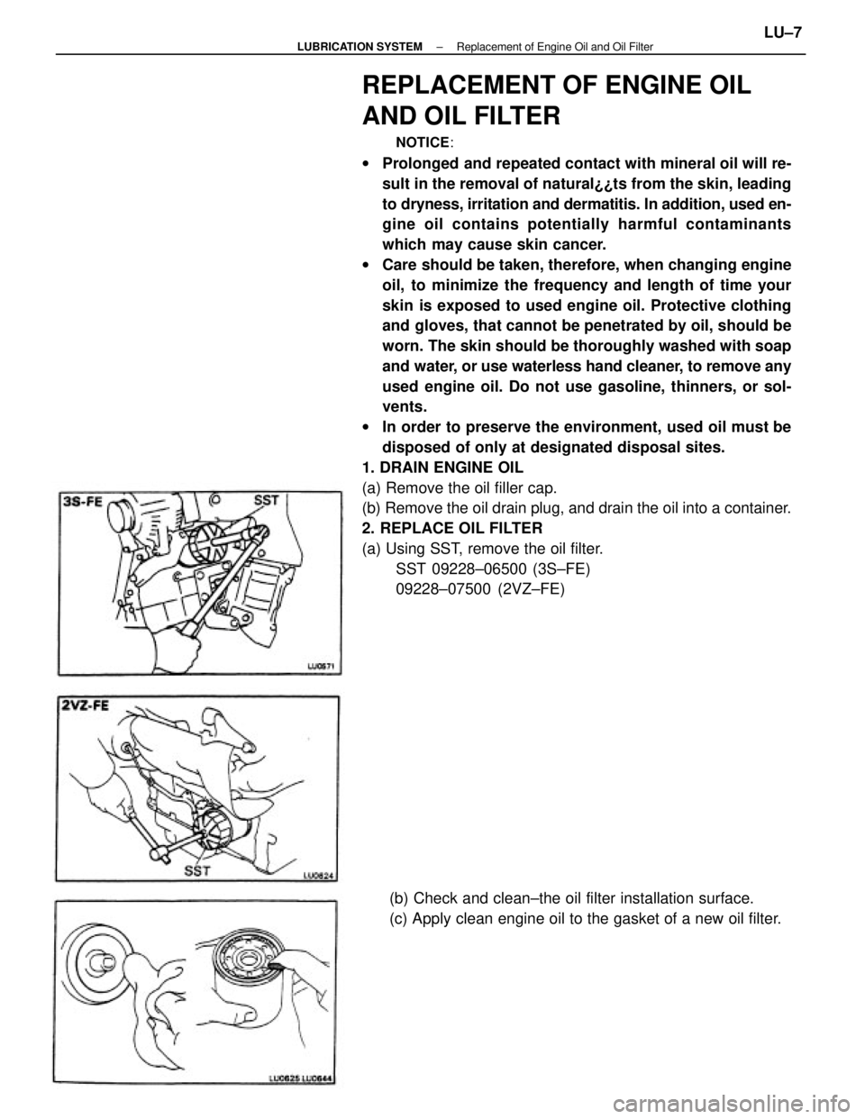
1. DRAIN ENGINE OIL
(a) Remove the oil filler cap.
(b) Remove the oil drain plug, and drain the oil into a container.
2. REPLACE OIL FILTER
(a) Using SST, remove the oil filter.
SST 09228±06500 (3S±FE)
09228±07500 (2VZ±FE)
(b) Check and clean±the oil filter installation surface.
(c) Apply clean engine oil to the gasket of a new oil filter.
± LUBRICATION SYSTEMReplacement of Engine Oil and Oil FilterLU±7
Page 1893 of 2389
3. FILL WITH ENGINE OIL
(a) Clean and install the oil drain plug with a new gasket.
Torque: 2VZ±FE 3S±FE 400 kg±cm (29 ft±lb, 39 N±m)
(b) Fill with new engine oil (API grade SG muitigrade,
fuel±efficient and recommended viscosity oil).
Capacity (3S±FE):
Drain and refill
w/ Oil filter change
4.1 liters (4.3 U S qts, 3.6 Imp. qts)
w/o Oil filter change
3.7 liters (3.9 US qts, 3.3 Imp. qts)
Dry fill 4.5 liters (4.8 U S qts, 4.4 Imp. qts)
Capacity (2VZ±FE):
Drain and refill
w/ Oil filter change
3.9 liters (4.1 US qts, 3.4 Imp. qts)
w/o Oil filter change
3.7 liters (3.9 US qts, 3.3 Imp. qts)
Dry fill 4.6 liters (4.8 US qts, 4.4 Imp. qts)
(c) Install the oil filler cap.
4. START ENGINE AND CHECK FOR LEAKS
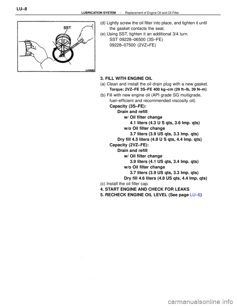
5. RECHECK ENGINE OIL LEVEL (See page LU±6) (d) Lightly screw the oil filter into place, and tighten it until
the gasket contacts the seat.
(e) Using SST, tighten it an additional 3/4 turn.
SST 09228±06500 (3S±FE)
09228±07500 (2VZ=FE)
± LUBRICATION SYSTEMReplacement of Engine Oil and Oil FilterLU±8