check engine TOYOTA CAMRY V20 1986 Service Information
[x] Cancel search | Manufacturer: TOYOTA, Model Year: 1986, Model line: CAMRY V20, Model: TOYOTA CAMRY V20 1986Pages: 2389, PDF Size: 84.44 MB
Page 1300 of 2389
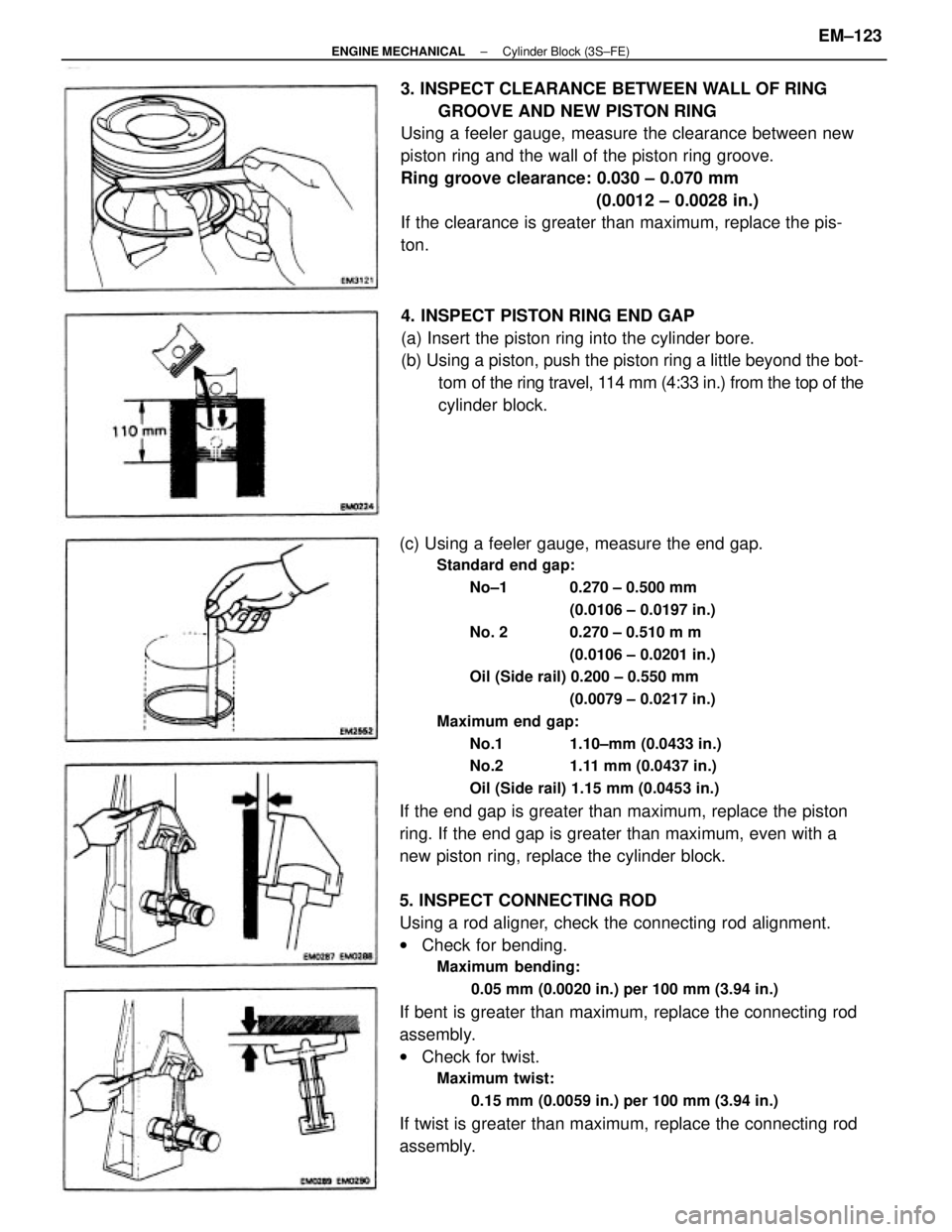
(c) Using a feeler gauge, measure the end gap.
Standard end gap:
No±1 0.270 ± 0.500 mm
(0.0106 ± 0.0197 in.)
No. 2 0.270 ± 0.510 m m
(0.0106 ± 0.0201 in.)
Oil (Side rail) 0.200 ± 0.550 mm
(0.0079 ± 0.0217 in.)
Maximum end gap:
No.1 1.10±mm (0.0433 in.)
No.2 1.11 mm (0.0437 in.)
Oil (Side rail) 1.15 mm (0.0453 in.)
If the end gap is greater than maximum, replace the piston
ring. If the end gap is greater than maximum, even with a
new piston ring, replace the cylinder block.
5. INSPECT CONNECTING ROD
Using a rod aligner, check the connecting rod alignment.
wCheck for bending.
Maximum bending:
0.05 mm (0.0020 in.) per 100 mm (3.94 in.)
If bent is greater than maximum, replace the connecting rod
assembly.
wCheck for twist.
Maximum twist:
0.15 mm (0.0059 in.) per 100 mm (3.94 in.)
If twist is greater than maximum, replace the connecting rod
assembly.3. INSPECT CLEARANCE BETWEEN WALL OF RING
GROOVE AND NEW PISTON RING
Using a feeler gauge, measure the clearance between new
piston ring and the wall of the piston ring groove.
Ring groove clearance: 0.030 ± 0.070 mm
(0.0012 ± 0.0028 in.)
If the clearance is greater than maximum, replace the pis-
ton.
4. INSPECT PISTON RING END GAP
(a) Insert the piston ring into the cylinder bore.
(b) Using a piston, push the piston ring a little beyond the bot-
tom of the ring travel, 114 mm (4:33 in.) from the top of the
cylinder block.
± ENGINE MECHANICALCylinder Block (3S±FE)EM±123
Page 1301 of 2389
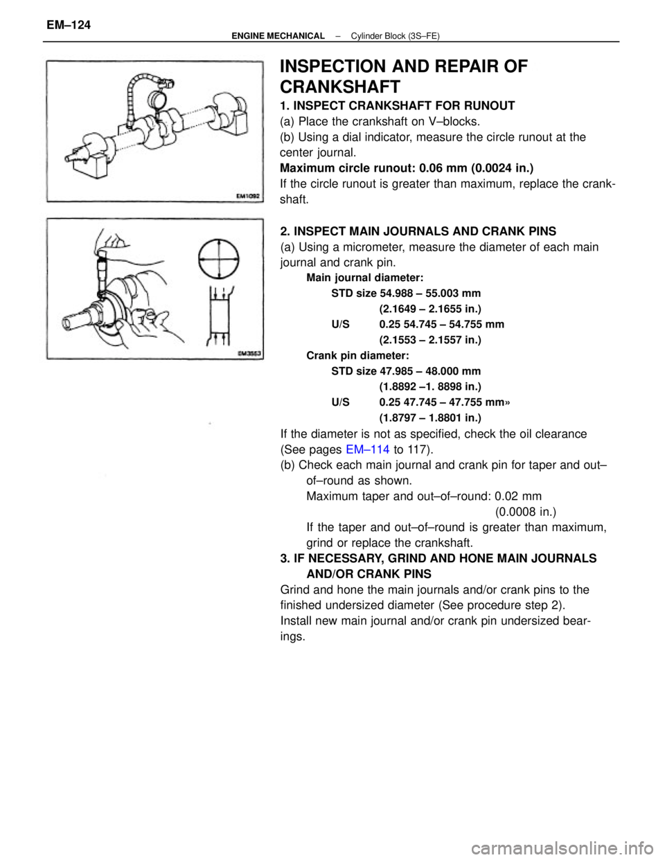
2. INSPECT MAIN JOURNALS AND CRANK PINS
(a) Using a micrometer, measure the diameter of each main
journal and crank pin.
Main journal diameter:
STD size 54.988 ± 55.003 mm
(2.1649 ± 2.1655 in.)
U/S 0.25 54.745 ± 54.755 mm
(2.1553 ± 2.1557 in.)
Crank pin diameter:
STD size 47.985 ± 48.000 mm
(1.8892 ±1. 8898 in.)
U/S 0.25 47.745 ± 47.755 mm»
(1.8797 ± 1.8801 in.)
If the diameter is not as specified, check the oil clearance
(See pages EM±114 to 117).
(b) Check each main journal and crank pin for taper and out±
of±round as shown.
Maximum taper and out±of±round: 0.02 mm
(0.0008 in.)
If the taper and out±of±round is greater than maximum,
grind or replace the crankshaft.
3. IF NECESSARY, GRIND AND HONE MAIN JOURNALS
AND/OR CRANK PINS
Grind and hone the main journals and/or crank pins to the
finished undersized diameter (See procedure step 2).
Install new main journal and/or crank pin undersized bear-
ings.
INSPECTION AND REPAIR OF
CRANKSHAFT
1. INSPECT CRANKSHAFT FOR RUNOUT
(a) Place the crankshaft on V±blocks.
(b) Using a dial indicator, measure the circle runout at the
center journal.
Maximum circle runout: 0.06 mm (0.0024 in.)
If the circle runout is greater than maximum, replace the crank-
shaft.
± ENGINE MECHANICALCylinder Block (3S±FE)EM±124
Page 1304 of 2389
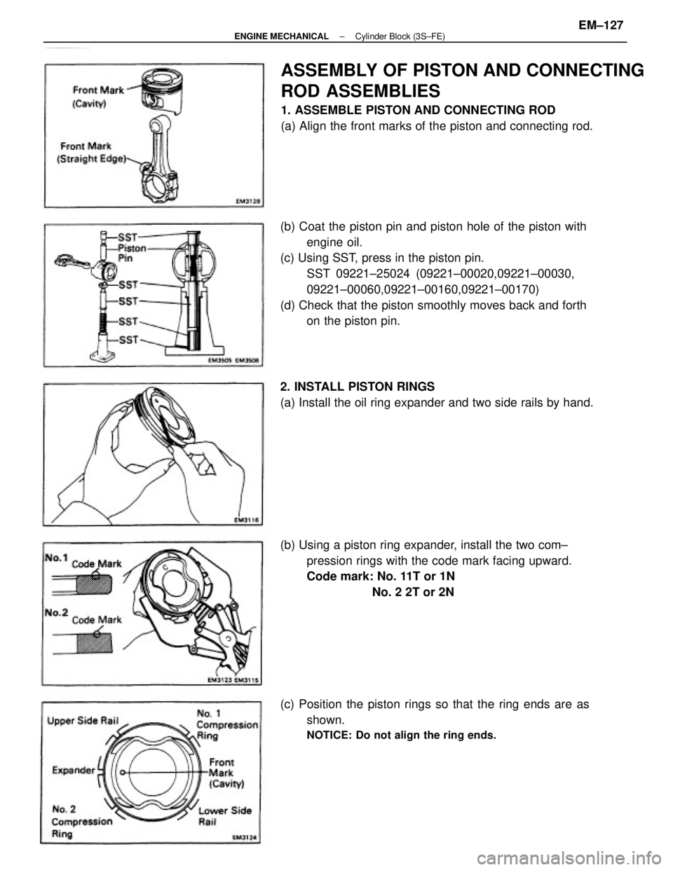
(b) Coat the piston pin and piston hole of the piston with
engine oil.
(c) Using SST, press in the piston pin.
SST 09221±25024 (09221±00020,09221±00030,
09221±00060,09221±00160,09221±00170)
(d) Check that the piston smoothly moves back and forth
on the piston pin.
ASSEMBLY OF PISTON AND CONNECTING
ROD ASSEMBLIES
1. ASSEMBLE PISTON AND CONNECTING ROD
(a) Align the front marks of the piston and connecting rod.
(b) Using a piston ring expander, install the two com±
pression rings with the code mark facing upward.
Code mark: No. 11T or 1N
No. 2 2T or 2N
(c) Position the piston rings so that the ring ends are as
shown.
NOTICE: Do not align the ring ends.
2. INSTALL PISTON RINGS
(a) Install the oil ring expander and two side rails by hand.
± ENGINE MECHANICALCylinder Block (3S±FE)EM±127
Page 1306 of 2389
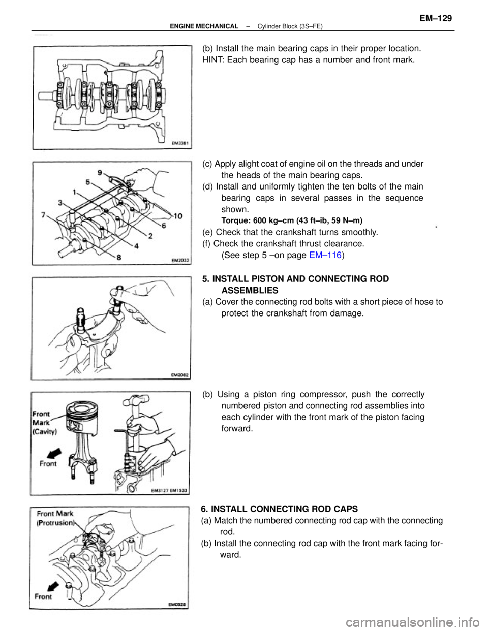
(c) Apply alight coat of engine oil on the threads and under
the heads of the main bearing caps.
(d) Install and uniformly tighten the ten bolts of the main
bearing caps in several passes in the sequence
shown.
Torque: 600 kg±cm (43 ft±ib, 59 N±m)
(e) Check that the crankshaft turns smoothly.
(f) Check the crankshaft thrust clearance.
(See step 5 ±on page EM±116)
6. INSTALL CONNECTING ROD CAPS
(a) Match the numbered connecting rod cap with the connecting
rod.
(b) Install the connecting rod cap with the front mark facing for-
ward. (b) Using a piston ring compressor, push the correctly
numbered piston and connecting rod assemblies into
each cylinder with the front mark of the piston facing
forward. 5. INSTALL PISTON AND CONNECTING ROD
ASSEMBLIES
(a) Cover the connecting rod bolts with a short piece of hose to
protect the crankshaft from damage. (b) Install the main bearing caps in their proper location.
HINT: Each bearing cap has a number and front mark.
± ENGINE MECHANICALCylinder Block (3S±FE)EM±129
Page 1307 of 2389
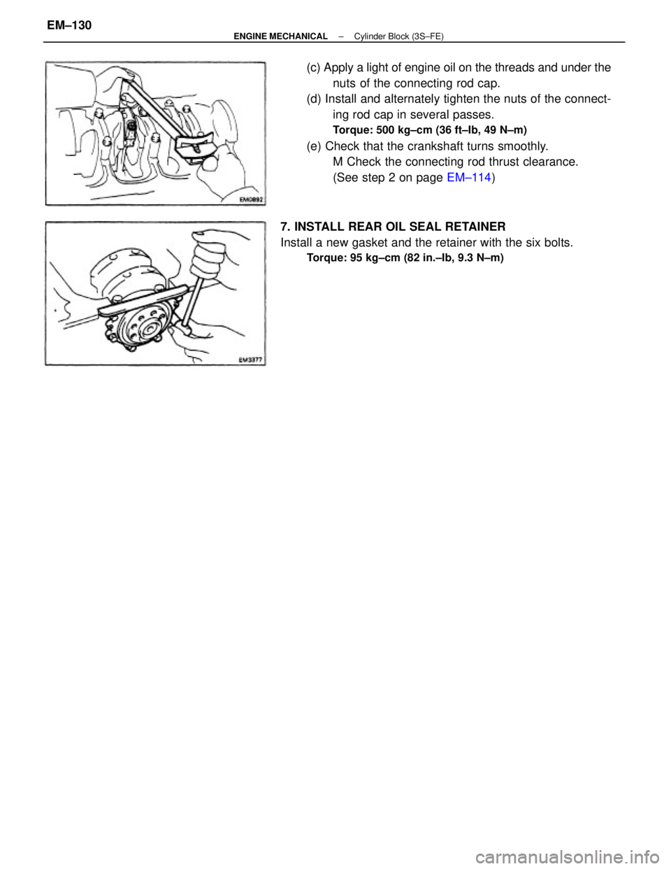
(c) Apply a light of engine oil on the threads and under the
nuts of the connecting rod cap.
(d) Install and alternately tighten the nuts of the connect-
ing rod cap in several passes.
Torque: 500 kg±cm (36 ft±Ib, 49 N±m)
(e) Check that the crankshaft turns smoothly.
M Check the connecting rod thrust clearance.
(See step 2 on page EM±114)
7. INSTALL REAR OIL SEAL RETAINER
Install a new gasket and the retainer with the six bolts.
Torque: 95 kg±cm (82 in.±Ib, 9.3 N±m)
± ENGINE MECHANICALCylinder Block (3S±FE)EM±130
Page 1313 of 2389
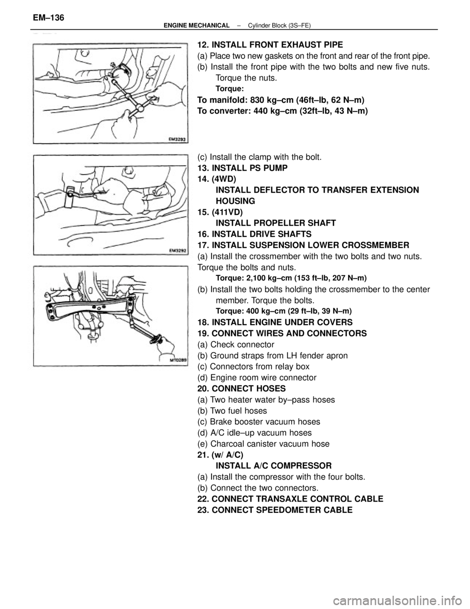
(c) Install the clamp with the bolt.
13. INSTALL PS PUMP
14. (4WD)
INSTALL DEFLECTOR TO TRANSFER EXTENSION
HOUSING
15. (411VD)
INSTALL PROPELLER SHAFT
16. INSTALL DRIVE SHAFTS
17. INSTALL SUSPENSION LOWER CROSSMEMBER
(a) Install the crossmember with the two bolts and two nuts.
Torque the bolts and nuts.
Torque: 2,100 kg±cm (153 ft±lb, 207 N±m)
(b) Install the two bolts holding the crossmember to the center
member. Torque the bolts.
Torque: 400 kg±cm (29 ft±Ib, 39 N±m)
18. INSTALL ENGINE UNDER COVERS
19. CONNECT WIRES AND CONNECTORS
(a) Check connector
(b) Ground straps from LH fender apron
(c) Connectors from relay box
(d) Engine room wire connector
20. CONNECT HOSES
(a) Two heater water by±pass hoses
(b) Two fuel hoses
(c) Brake booster vacuum hoses
(d) A/C idle±up vacuum hoses
(e) Charcoal canister vacuum hose
21. (w/ A/C)
INSTALL A/C COMPRESSOR
(a) Install the compressor with the four bolts.
(b) Connect the two connectors.
22. CONNECT TRANSAXLE CONTROL CABLE
23. CONNECT SPEEDOMETER CABLE 12. INSTALL FRONT EXHAUST PIPE
(a) Place two new gaskets on the front and rear of the front pipe.
(b) Install the front pipe with the two bolts and new five nuts.
Torque the nuts.
Torque:
To manifold: 830 kg±cm (46ft±Ib, 62 N±m)
To converter: 440 kg±cm (32ft±lb, 43 N±m)
± ENGINE MECHANICALCylinder Block (3S±FE)EM±136
Page 1315 of 2389
32. INSTALL BATTERY
33. FILL WITH ENGINE COOLANT (See page CO±5)
Capacity (w/ Heater):
M/T 6.4 liters (6.8 US qts, 5.6 Imp. qts)
A/T (2WD) 6.3 liters (6.7 US qts, 5.5 Imp. qts)
A/T (4WD) 6.8 liters (7.2 US qts, 6.0 Imp. qts)
34. FILL WITH ENGINE OIL (See page LU±8)
Capacity:
Drain and refill
w/ Oil filter change
3.9 liters (4.1 US qts, 3.4 Imp. qts)
w/o Oil filter change
3.7 liters (3.9 US qts, 3.3 Imp. qts)
Dry fill 4.3 liters (4.5 US qts, 3.8 Imp. qts)
35. START ENGINE AND CHECK FOR LEAKS
36. PERFORM ENGINE ADJUSTMENT
(a) Adjust the alternator drive belt.
(See page CH±3)
Drive belt tension:
w/ A/C New belt 175 + 5 lb
Used belt 130 + 10 lb
w/o A/C New belt 125 + 25 lb
Used belt 95 + 20 lb
(b) Adjust the PS drive belt.
Drive belt tension: New belt 125 + 25 lb
Used belt 80 + 20 lb
(c) Adjust the ignition timing.
(See steps 7 to 10 on pages IG±16 and 17)
Ignition timing:
10° BTDC @ idle
(w/ Terminals TE 1 and E1 connected)
(d) Adjust the valve. clearance. (See page EM±11)
Valve clearance:
Intake 0.19 ± 0.29 mm (0.007 ± 0.011 in.)
Exhaust 0.28 ± 0.38 mm (0.011 ± 0.015 in.)
37. INSTALL HOOD
38. PERFORM ROAD TEST
Check for abnormal noise, shock, slippage, correct shift
points and smooth operation.
39. RECHECK ENGINE COOLANT AND ENGINE OIL
LEVELS
± ENGINE MECHANICALCylinder Block (3S±FE)EM±138
Page 1318 of 2389
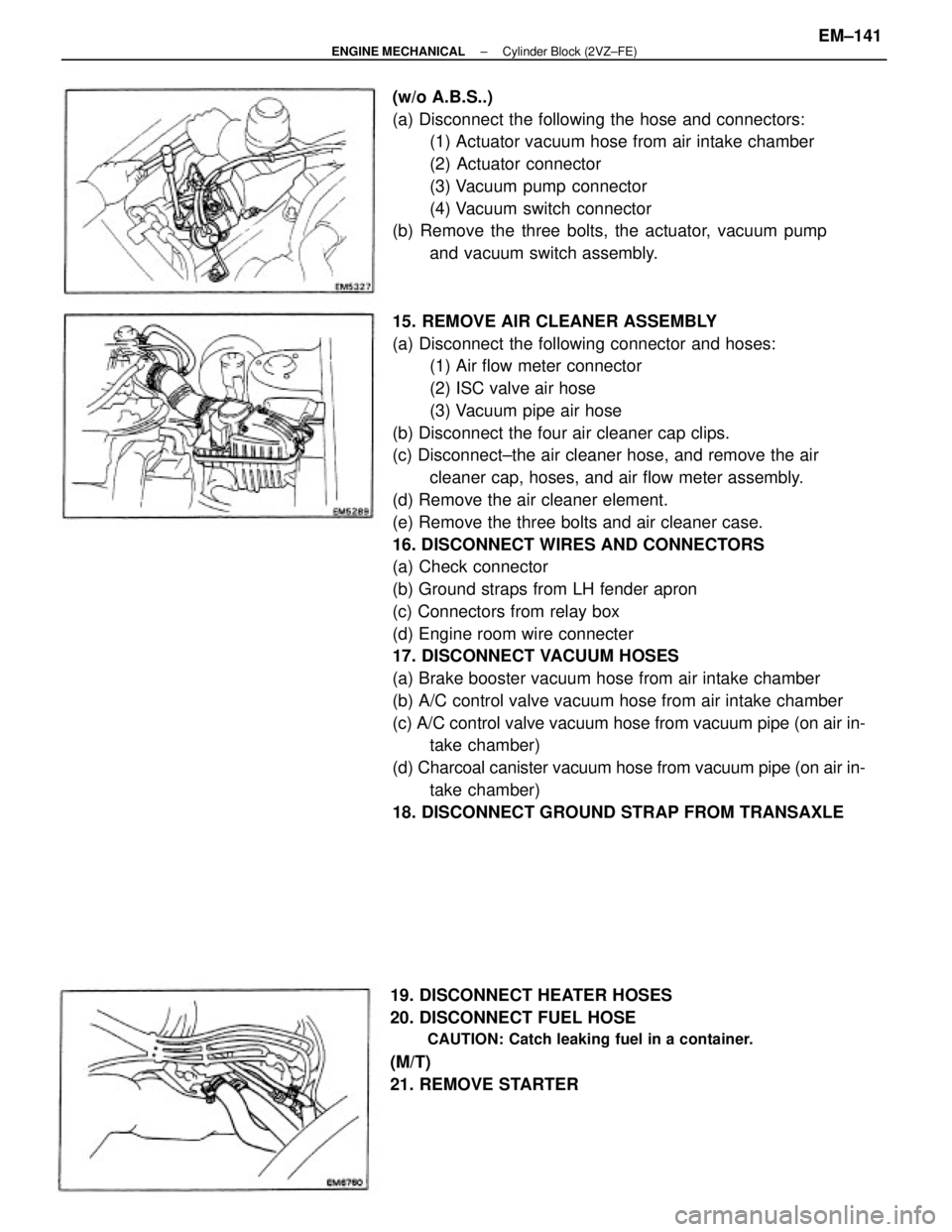
15. REMOVE AIR CLEANER ASSEMBLY
(a) Disconnect the following connector and hoses:
(1) Air flow meter connector
(2) ISC valve air hose
(3) Vacuum pipe air hose
(b) Disconnect the four air cleaner cap clips.
(c) Disconnect±the air cleaner hose, and remove the air
cleaner cap, hoses, and air flow meter assembly.
(d) Remove the air cleaner element.
(e) Remove the three bolts and air cleaner case.
16. DISCONNECT WIRES AND CONNECTORS
(a) Check connector
(b) Ground straps from LH fender apron
(c) Connectors from relay box
(d) Engine room wire connecter
17. DISCONNECT VACUUM HOSES
(a) Brake booster vacuum hose from air intake chamber
(b) A/C control valve vacuum hose from air intake chamber
(c) A/C control valve vacuum hose from vacuum pipe (on air in-
take chamber)
(d) Charcoal canister vacuum hose from vacuum pipe (on air in-
take chamber)
18. DISCONNECT GROUND STRAP FROM TRANSAXLE (w/o A.B.S..)
(a) Disconnect the following the hose and connectors:
(1) Actuator vacuum hose from air intake chamber
(2) Actuator connector
(3) Vacuum pump connector
(4) Vacuum switch connector
(b) Remove the three bolts, the actuator, vacuum pump
and vacuum switch assembly.
19. DISCONNECT HEATER HOSES
20. DISCONNECT FUEL HOSE
CAUTION: Catch leaking fuel in a container.
(M/T)
21. REMOVE STARTER
± ENGINE MECHANICALCylinder Block (2VZ±FE)EM±141
Page 1324 of 2389
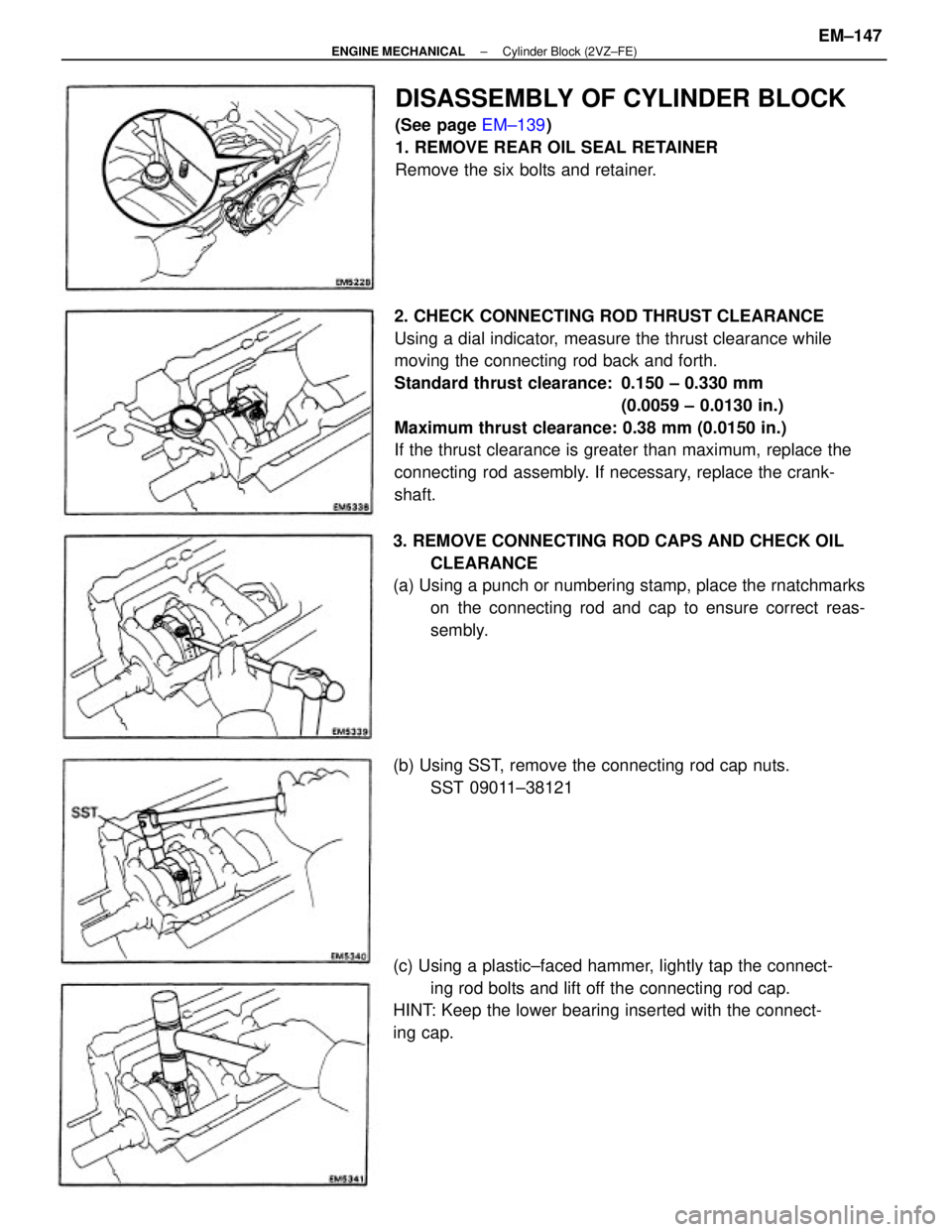
2. CHECK CONNECTING ROD THRUST CLEARANCE
Using a dial indicator, measure the thrust clearance while
moving the connecting rod back and forth.
Standard thrust clearance: 0.150 ± 0.330 mm
(0.0059 ± 0.0130 in.)
Maximum thrust clearance: 0.38 mm (0.0150 in.)
If the thrust clearance is greater than maximum, replace the
connecting rod assembly. If necessary, replace the crank-
shaft.
3. REMOVE CONNECTING ROD CAPS AND CHECK OIL
CLEARANCE
(a) Using a punch or numbering stamp, place the rnatchmarks
on the connecting rod and cap to ensure correct reas-
sembly.
(c) Using a plastic±faced hammer, lightly tap the connect-
ing rod bolts and lift off the connecting rod cap.
HINT: Keep the lower bearing inserted with the connect-
ing cap.
DISASSEMBLY OF CYLINDER BLOCK
(See page EM±139)
1. REMOVE REAR OIL SEAL RETAINER
Remove the six bolts and retainer.
(b) Using SST, remove the connecting rod cap nuts.
SST 09011±38121
± ENGINE MECHANICALCylinder Block (2VZ±FE)EM±147
Page 1325 of 2389
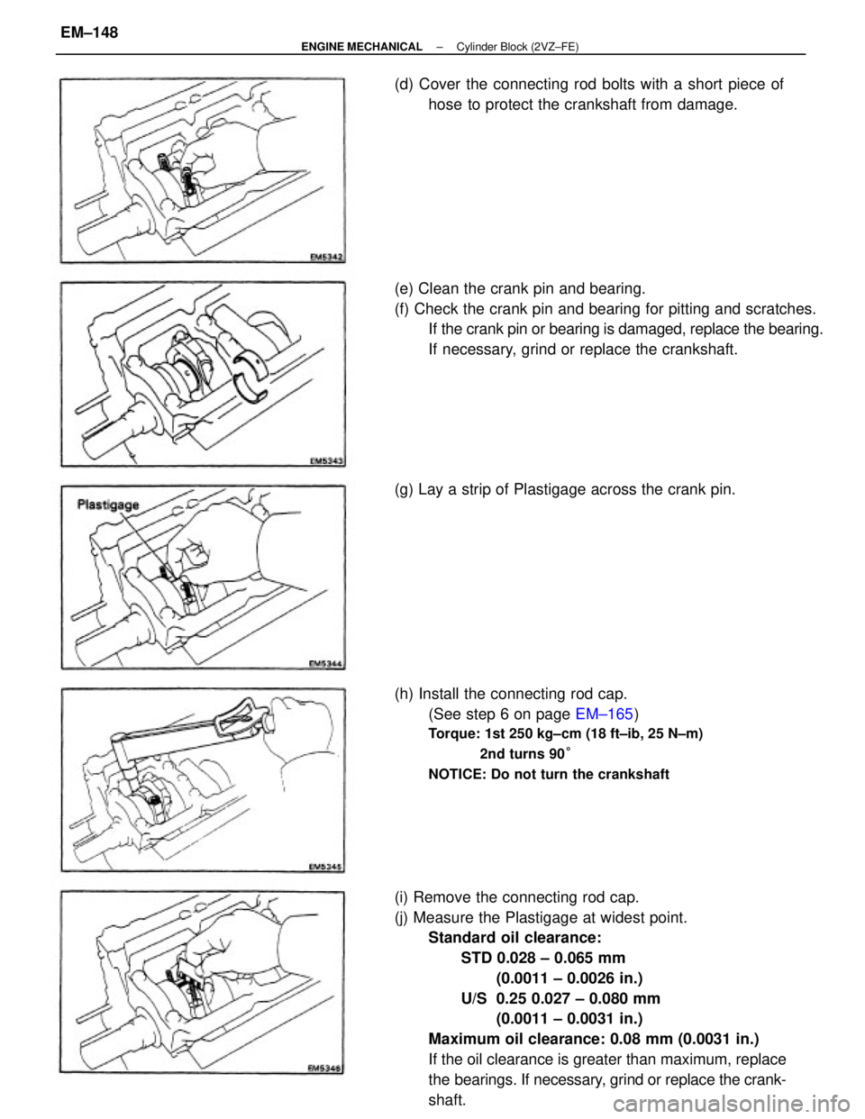
(i) Remove the connecting rod cap.
(j) Measure the Plastigage at widest point.
Standard oil clearance:
STD 0.028 ± 0.065 mm
(0.0011 ± 0.0026 in.)
U/S 0.25 0.027 ± 0.080 mm
(0.0011 ± 0.0031 in.)
Maximum oil clearance: 0.08 mm (0.0031 in.)
If the oil clearance is greater than maximum, replace
the bearings. If necessary, grind or replace the crank-
shaft. (e) Clean the crank pin and bearing.
(f) Check the crank pin and bearing for pitting and scratches.
If the crank pin or bearing is damaged, replace the bearing.
If necessary, grind or replace the crankshaft.
(h) Install the connecting rod cap.
(See step 6 on page EM±165)
Torque: 1st 250 kg±cm (18 ft±ib, 25 N±m)
2nd turns 90°
NOTICE: Do not turn the crankshaft
(d) Cover the connecting rod bolts with a short piece of
hose to protect the crankshaft from damage.
(g) Lay a strip of Plastigage across the crank pin.
± ENGINE MECHANICALCylinder Block (2VZ±FE)EM±148