engine TOYOTA CAMRY V20 1986 Service Information
[x] Cancel search | Manufacturer: TOYOTA, Model Year: 1986, Model line: CAMRY V20, Model: TOYOTA CAMRY V20 1986Pages: 2389, PDF Size: 84.44 MB
Page 261 of 2389
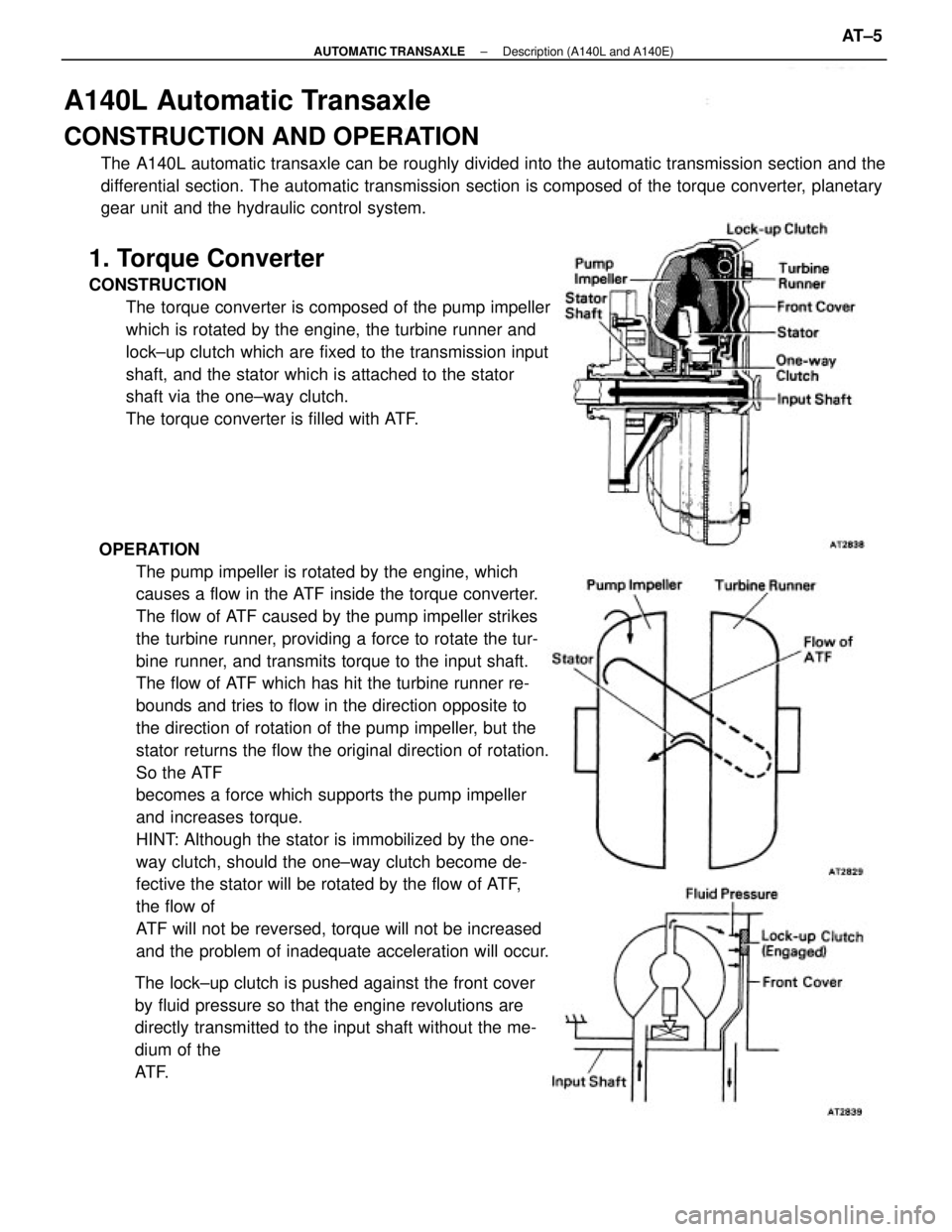
A140L Automatic Transaxle
CONSTRUCTION AND OPERATION
The A140L automatic transaxle can be roughly divided into the automatic transmission section and the
differential section. The automatic transmission section is composed of the torque converter, planetary
gear unit and the hydraulic control system.
OPERATION
The pump impeller is rotated by the engine, which
causes a flow in the ATF inside the torque converter.
The flow of ATF caused by the pump impeller strikes
the turbine runner, providing a force to rotate the tur-
bine runner, and transmits torque to the input shaft.
The flow of ATF which has hit the turbine runner re-
bounds and tries to flow in the direction opposite to
the direction of rotation of the pump impeller, but the
stator returns the flow the original direction of rotation.
So the ATF
becomes a force which supports the pump impeller
and increases torque.
HINT: Although the stator is immobilized by the one-
way clutch, should the one±way clutch become de-
fective the stator will be rotated by the flow of ATF,
the flow of
ATF will not be reversed, torque will not be increased
and the problem of inadequate acceleration will occur.
The lock±up clutch is pushed against the front cover
by fluid pressure so that the engine revolutions are
directly transmitted to the input shaft without the me-
dium of the
AT F.
1. Torque Converter
CONSTRUCTION
The torque converter is composed of the pump impeller
which is rotated by the engine, the turbine runner and
lock±up clutch which are fixed to the transmission input
shaft, and the stator which is attached to the stator
shaft via the one±way clutch.
The torque converter is filled with ATF.
± AUTOMATIC TRANSAXLEDescription (A140L and A140E)AT±5
Page 263 of 2389
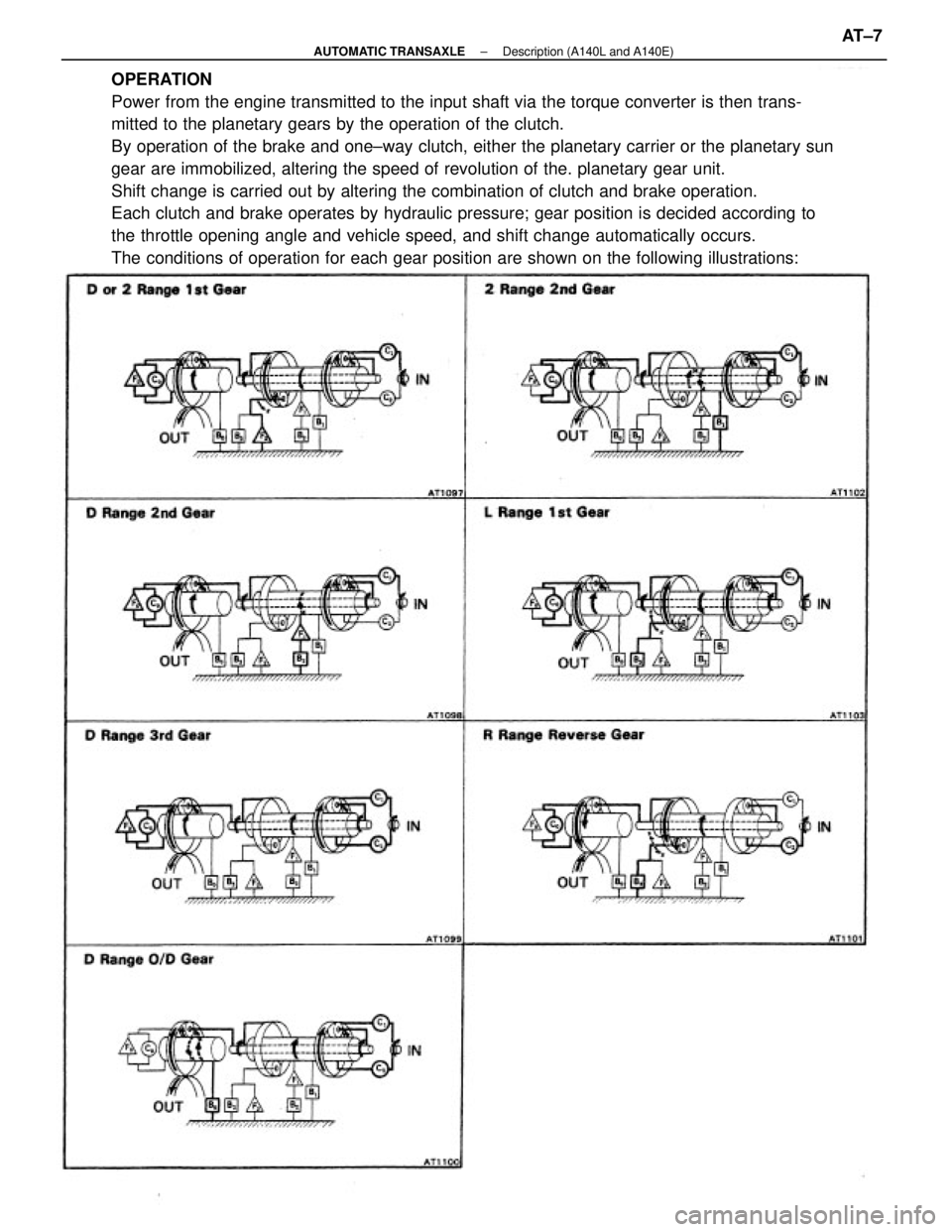
OPERATION
Power from the engine transmitted to the input shaft via the torque converter is then trans-
mitted to the planetary gears by the operation of the clutch.
By operation of the brake and one±way clutch, either the planetary carrier or the planetary sun
gear are immobilized, altering the speed of revolution of the. planetary gear unit.
Shift change is carried out by altering the combination of clutch and brake operation.
Each clutch and brake operates by hydraulic pressure; gear position is decided according to
the throttle opening angle and vehicle speed, and shift change automatically occurs.
The conditions of operation for each gear position are shown on the following illustrations:
± AUTOMATIC TRANSAXLEDescription (A140L and A140E)AT±7
Page 264 of 2389
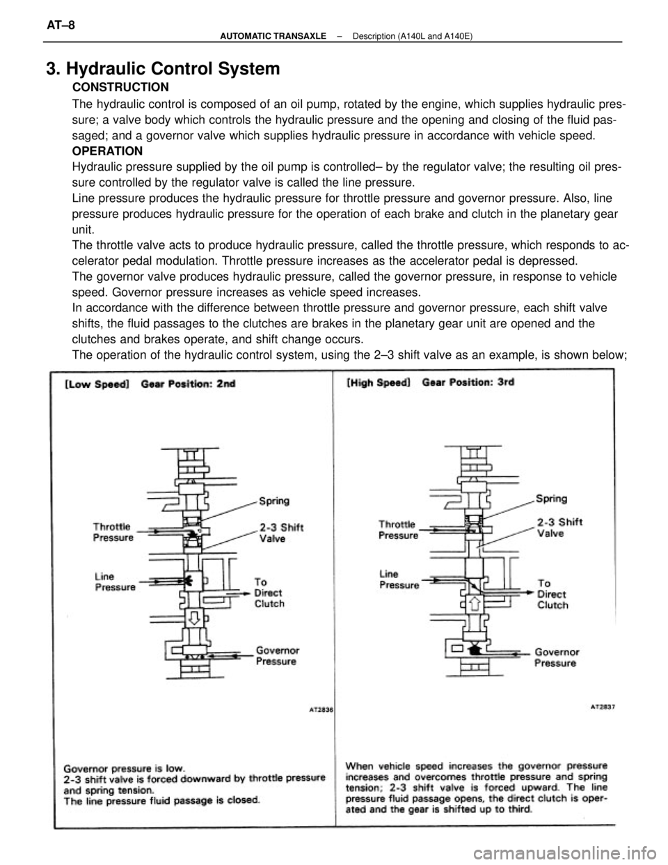
3. Hydraulic Control System
CONSTRUCTION
The hydraulic control is composed of an oil pump, rotated by the engine, which supplies hydraulic pres-
sure; a valve body which controls the hydraulic pressure and the opening and closing of the fluid pas-
saged; and a governor valve which supplies hydraulic pressure in accordance with vehicle speed.
OPERATION
Hydraulic pressure supplied by the oil pump is controlled± by the regulator valve; the resulting oil pres-
sure controlled by the regulator valve is called the line pressure.
Line pressure produces the hydraulic pressure for throttle pressure and governor pressure. Also, line
pressure produces hydraulic pressure for the operation of each brake and clutch in the planetary gear
unit.
The throttle valve acts to produce hydraulic pressure, called the throttle pressure, which responds to ac-
celerator pedal modulation. Throttle pressure increases as the accelerator pedal is depressed.
The governor valve produces hydraulic pressure, called the governor pressure, in response to vehicle
speed. Governor pressure increases as vehicle speed increases.
In accordance with the difference between throttle pressure and governor pressure, each shift valve
shifts, the fluid passages to the clutches are brakes in the planetary gear unit are opened and the
clutches and brakes operate, and shift change occurs.
The operation of the hydraulic control system, using the 2±3 shift valve as an example, is shown below;
± AUTOMATIC TRANSAXLEDescription (A140L and A140E)AT±8
Page 266 of 2389
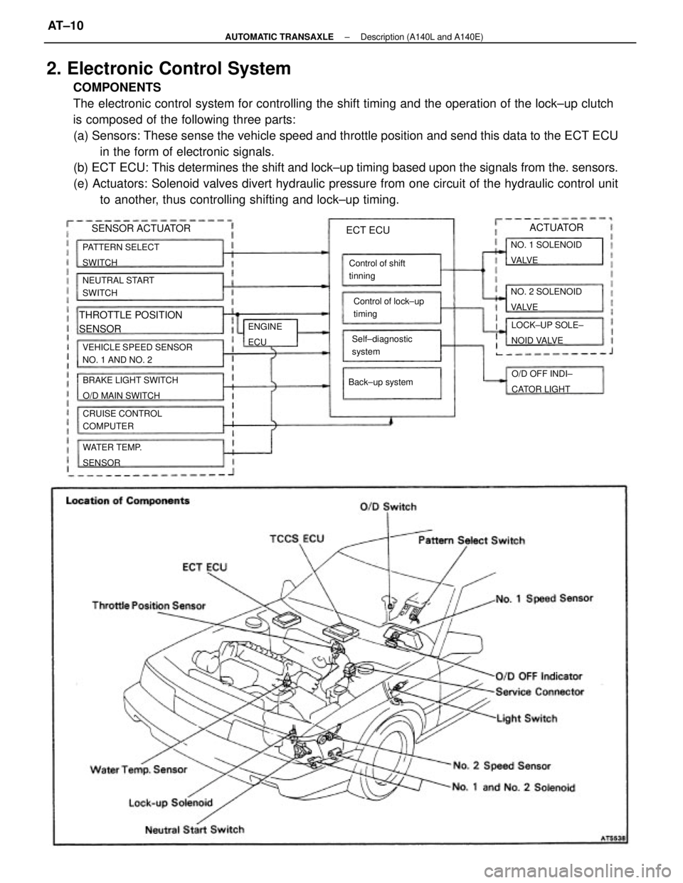
2. Electronic Control System
COMPONENTS
The electronic control system for controlling the shift timing and the operation of the lock±up clutch
is composed of the following three parts:
(a) Sensors: These sense the vehicle speed and throttle position and send this data to the ECT ECU
in the form of electronic signals.
(b) ECT ECU: This determines the shift and lock±up timing based upon the signals from the. sensors.
(e) Actuators: Solenoid valves divert hydraulic pressure from one circuit of the hydraulic control unit
to another, thus controlling shifting and lock±up timing.
VEHICLE SPEED SENSOR
NO. 1 AND NO. 2
BRAKE LIGHT SWITCH
O/D MAIN SWITCH
THROTTLE POSITION
SENSOR
CRUISE CONTROL
COMPUTER PATTERN SELECT
SWITCH
NEUTRAL START
SWITCH
LOCK±UP SOLE±
NOID VALVE NO. 2 SOLENOID
VA LV E NO. 1 SOLENOID
VA LV E
Control of shift
tinning
Self±diagnostic
systemControl of lock±up
timing
WATER TEMP.
SENSORO/D OFF INDI±
CATOR LIGHT Back±up system
ECT ECU
ENGINE
ECU
ACTUATOR
SENSOR ACTUATOR
± AUTOMATIC TRANSAXLEDescription (A140L and A140E)AT±10
Page 268 of 2389
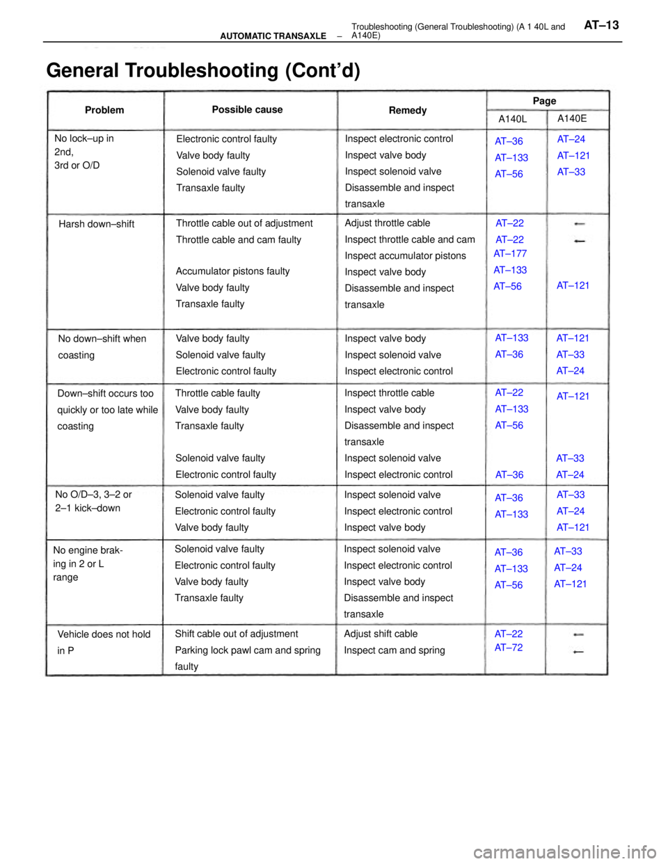
Adjust throttle cable
Inspect throttle cable and cam
Inspect accumulator pistons
Inspect valve body
Disassemble and inspect
transaxle
Inspect throttle cable
Inspect valve body
Disassemble and inspect
transaxle
Inspect solenoid valve
Inspect electronic control
Inspect solenoid valve
Inspect electronic control
Inspect valve body
Disassemble and inspect
transaxleInspect electronic control
Inspect valve body
Inspect solenoid valve
Disassemble and inspect
transaxle
Solenoid valve faulty
Electronic control faulty
Valve body faulty
Transaxle faultyElectronic control faulty
Valve body faulty
Solenoid valve faulty
Transaxle faulty
General Troubleshooting (Cont'd)
Shift cable out of adjustment
Parking lock pawl cam and spring
faultyAccumulator pistons faulty
Valve body faulty
Transaxle faulty
Inspect valve body
Inspect solenoid valve
Inspect electronic control
Inspect solenoid valve
Inspect electronic control
Inspect valve body Solenoid valve faulty
Electronic control faulty
Valve body faultyValve body faulty
Solenoid valve faulty
Electronic control faultyThrottle cable out of adjustment
Throttle cable and cam faulty
Throttle cable faulty
Valve body faulty
Transaxle faulty Down±shift occurs too
quickly or too late while
coasting
Solenoid valve faulty
Electronic control faulty
Adjust shift cable
Inspect cam and spring No down±shift when
coastingAT±36
AT±133
AT±56
AT±33
AT±24
AT±121 No engine brak-
ing in 2 or L
rangeAT±24
AT±121
AT±33
AT±36
AT±133
AT±56 No lock±up in
2nd,
3rd or O/D
No O/D±3, 3±2 or
2±1 kick±down
Vehicle does not hold
in PAT±177
AT±133
AT±56
AT±121
AT±33
AT±24 AT±133
AT±36
AT±22
AT±133
AT±56
AT±33
AT±24
AT±121 AT±36
AT±133AT±121 AT±121 Harsh down±shiftPossible cause
AT±33
AT±24
AT±22
AT±72AT±22
AT±22
AT±36A140E Problem
Remedy
A140LPage
± AUTOMATIC TRANSAXLETroubleshooting (General Troubleshooting) (A 1 40L and
A140E)AT±13
Page 271 of 2389
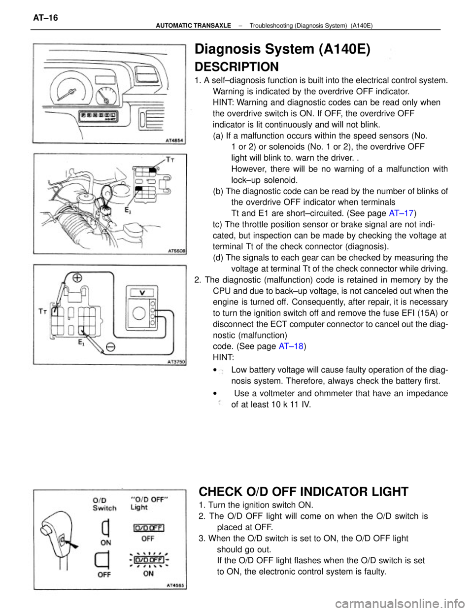
Diagnosis System (A140E)
DESCRIPTION
1. A self±diagnosis function is built into the electrical control system.
Warning is indicated by the overdrive OFF indicator.
HINT: Warning and diagnostic codes can be read only when
the overdrive switch is ON. If OFF, the overdrive OFF
indicator is lit continuously and will not blink.
(a) If a malfunction occurs within the speed sensors (No.
1 or 2) or solenoids (No. 1 or 2), the overdrive OFF
light will blink to. warn the driver. .
However, there will be no warning of a malfunction with
lock±up solenoid.
(b) The diagnostic code can be read by the number of blinks of
the overdrive OFF indicator when terminals
Tt and E1 are short±circuited. (See page AT±17)
tc) The throttle position sensor or brake signal are not indi-
cated, but inspection can be made by checking the voltage at
terminal Tt of the check connector (diagnosis).
(d) The signals to each gear can be checked by measuring the
voltage at terminal Tt of the check connector while driving.
2. The diagnostic (malfunction) code is retained in memory by the
CPU and due to back±up voltage, is not canceled out when the
engine is turned off. Consequently, after repair, it is necessary
to turn the ignition switch off and remove the fuse EFI (15A) or
disconnect the ECT computer connector to cancel out the diag-
nostic (malfunction)
code. (See page AT±18)
HINT:
wLow battery voltage will cause faulty operation of the diag-
nosis system. Therefore, always check the battery first.
w Use a voltmeter and ohmmeter that have an impedance
of at least 10 k 11 IV.
CHECK O/D OFF INDICATOR LIGHT
1. Turn the ignition switch ON.
2. The O/D OFF light will come on when the O/D switch is
placed at OFF.
3. When the O/D switch is set to ON, the O/D OFF light
should go out.
If the O/D OFF light flashes when the O/D switch is set
to ON, the electronic control system is faulty.
± AUTOMATIC TRANSAXLETroubleshooting (Diagnosis System) (A140E)AT±16
Page 272 of 2389
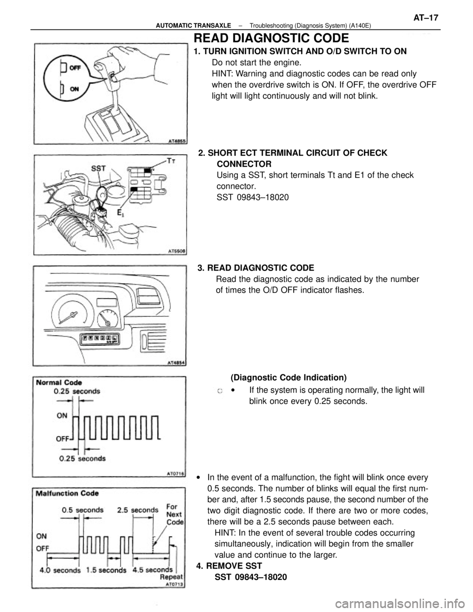
wIn the event of a malfunction, the fight will blink once every
0.5 seconds. The number of blinks will equal the first num-
ber and, after 1.5 seconds pause, the second number of the
two digit diagnostic code. If there are two or more codes,
there will be a 2.5 seconds pause between each.
HINT: In the event of several trouble codes occurring
simultaneously, indication will begin from the smaller
value and continue to the larger.
4. REMOVE SST
SST 09843±18020
READ DIAGNOSTIC CODE
1. TURN IGNITION SWITCH AND O/D SWITCH TO ON
Do not start the engine.
HINT: Warning and diagnostic codes can be read only
when the overdrive switch is ON. If OFF, the overdrive OFF
light will light continuously and will not blink.
2. SHORT ECT TERMINAL CIRCUIT OF CHECK
CONNECTOR
Using a SST, short terminals Tt and E1 of the check
connector.
SST 09843±18020
(Diagnostic Code Indication)
wIf the system is operating normally, the light will
blink once every 0.25 seconds. 3. READ DIAGNOSTIC CODE
Read the diagnostic code as indicated by the number
of times the O/D OFF indicator flashes.
± AUTOMATIC TRANSAXLETroubleshooting (Diagnosis System) (A140E)AT±17
Page 276 of 2389
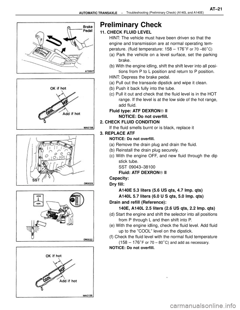
Preliminary Check
11. CHECK FLUID LEVEL
HINT: The vehicle must have been driven so that the
engine and transmission are at normal operating tem-
perature. (fluid temperature: 158 ± 176
°F or 70 ±80°C)
(a) Park the vehicle on a level surface, set the parking
brake.
(b) With the engine idling, shift the shift lever into all posi-
tions from P to L position and return to P position.
HINT: Depress the brake pedal.
(a) Pull out the transaxle dipstick and wipe it clean.
(b) Push it back fully into the tube.
(c) Pull it out and check that the fluid level is in the HOT
range. If the level is at the low side of the hot range,
add fluid.
Fluid type: ATF DEXRON) II
NOTICE: Do not overfill.
2. CHECK FLUID CONDITION
If the fluid smells burnt or is black, replace it
3. REPLACE ATF
NOTICE: Do not overfill.
(a) Remove the drain plug and drain the fluid.
(b) Reinstall the drain plug securely.
(c) With the engine OFF, and new fluid through the dip
stick tube.
SST 09043±38100
Fluid: ATF DEXRON) II
Capacity:
Dry fill:
A140E 5.3 liters (5.6 US qts, 4.7 Imp. qts)
A140L 5.7 liters (6.0 U S qts, 5.0 Imp. qts)
Drain and refill (Reference):
140E, A140L 2.5 liters (2.6 US qts, 2.2 Imp. qts)
(d) Start the engine and shift the selector into all positions
from P through L and then shift into P.
(e) With the engine idling, check the fluid level. Add fluid
up to the ºCOOLº level on the dipstick.
(f) Check the fluid level with the normal fluid temperature
(158 ± 176
°F or 70 ± 80°C) and add as necessary.
NOTICE: Do not overfill.
± AUTOMATIC TRANSAXLETroubleshooting (Preliminary Check) (A140L and A140E)AT±21
Page 277 of 2389
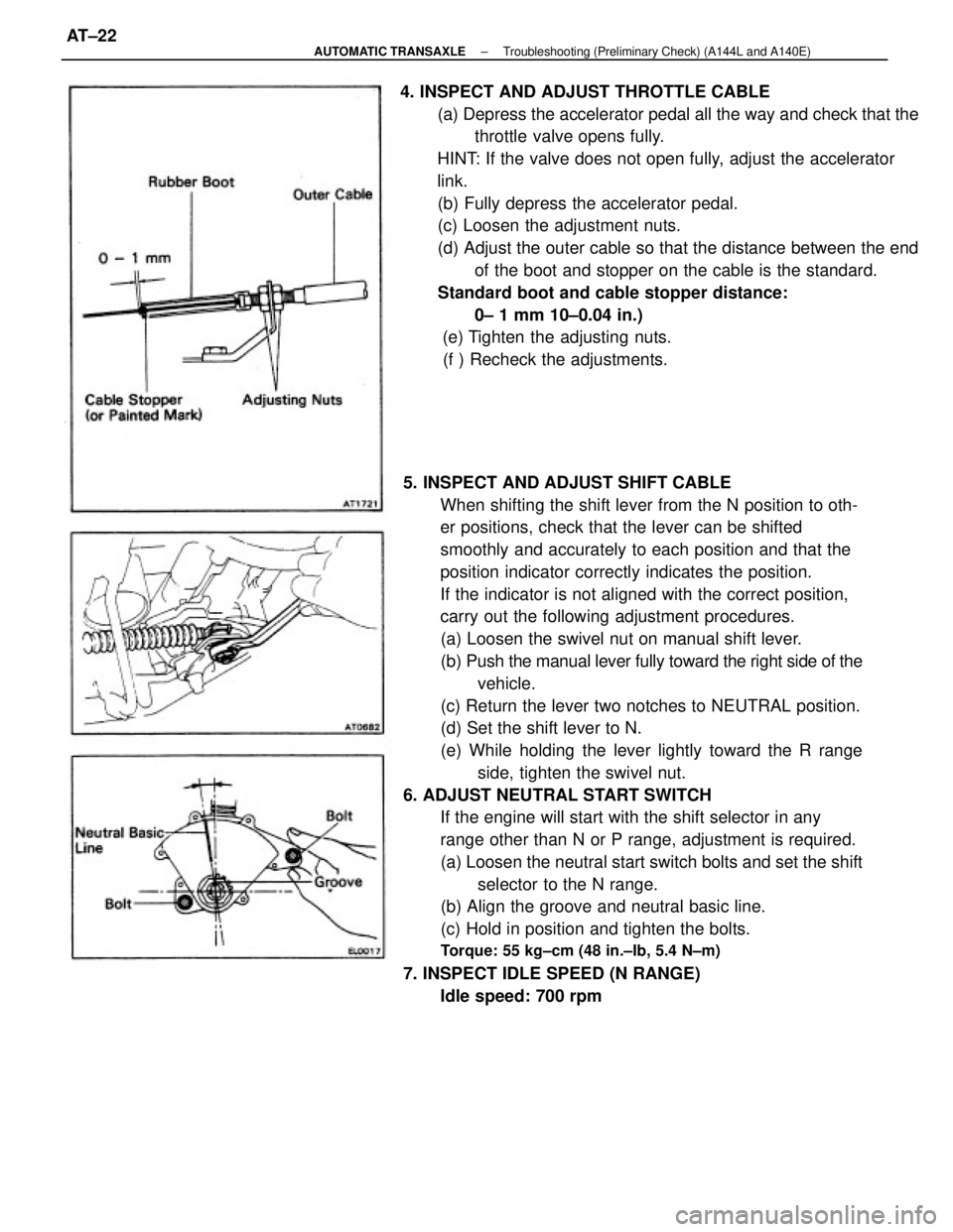
5. INSPECT AND ADJUST SHIFT CABLE
When shifting the shift lever from the N position to oth-
er positions, check that the lever can be shifted
smoothly and accurately to each position and that the
position indicator correctly indicates the position.
If the indicator is not aligned with the correct position,
carry out the following adjustment procedures.
(a) Loosen the swivel nut on manual shift lever.
(b) Push the manual lever fully toward the right side of the
vehicle.
(c) Return the lever two notches to NEUTRAL position.
(d) Set the shift lever to N.
(e) While holding the lever lightly toward the R range
side, tighten the swivel nut.
6. ADJUST NEUTRAL START SWITCH
If the engine will start with the shift selector in any
range other than N or P range, adjustment is required.
(a) Loosen the neutral start switch bolts and set the shift
selector to the N range.
(b) Align the groove and neutral basic line.
(c) Hold in position and tighten the bolts.
Torque: 55 kg±cm (48 in.±Ib, 5.4 N±m)
7. INSPECT IDLE SPEED (N RANGE)
Idle speed: 700 rpm 4. INSPECT AND ADJUST THROTTLE CABLE
(a) Depress the accelerator pedal all the way and check that the
throttle valve opens fully.
HINT: If the valve does not open fully, adjust the accelerator
link.
(b) Fully depress the accelerator pedal.
(c) Loosen the adjustment nuts.
(d) Adjust the outer cable so that the distance between the end
of the boot and stopper on the cable is the standard.
Standard boot and cable stopper distance:
0± 1 mm 10±0.04 in.)
(e) Tighten the adjusting nuts.
(f ) Recheck the adjustments.
± AUTOMATIC TRANSAXLETroubleshooting (Preliminary Check) (A144L and A140E)AT±22
Page 278 of 2389
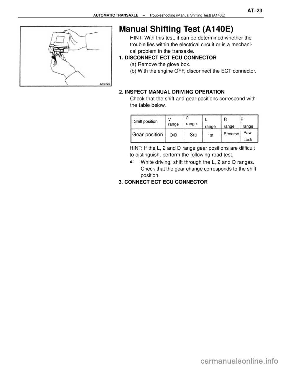
Manual Shifting Test (A140E)
HINT: With this test, it can be determined whether the
trouble lies within the electrical circuit or is a mechani-
cal problem in the transaxle.
1. DISCONNECT ECT ECU CONNECTOR
(a) Remove the glove box.
(b) With the engine OFF, disconnect the ECT connector.
HINT: If the L, 2 and D range gear positions are difficult
to distinguish, perform the following road test.
wWhite driving, shift through the L, 2 and D ranges.
Check that the gear change corresponds to the shift
position.
3. CONNECT ECT ECU CONNECTOR2. INSPECT MANUAL DRIVING OPERATION
Check that the shift and gear positions correspond with
the table below.
Gear position
Shift positionP
' range R
range 2
range V
rangeL
range
Pawl
Lock Reverse
O/D 1st
3rd
± AUTOMATIC TRANSAXLETroubleshooting (Manual Shifting Test) (A140E)AT±23