mirror TOYOTA COROLLA 2022 (in English) Owner's Manual
[x] Cancel search | Manufacturer: TOYOTA, Model Year: 2022, Model line: COROLLA, Model: TOYOTA COROLLA 2022Pages: 678, PDF Size: 147.24 MB
Page 194 of 678
1924-5. Using the driving support systems
WA R N I N G
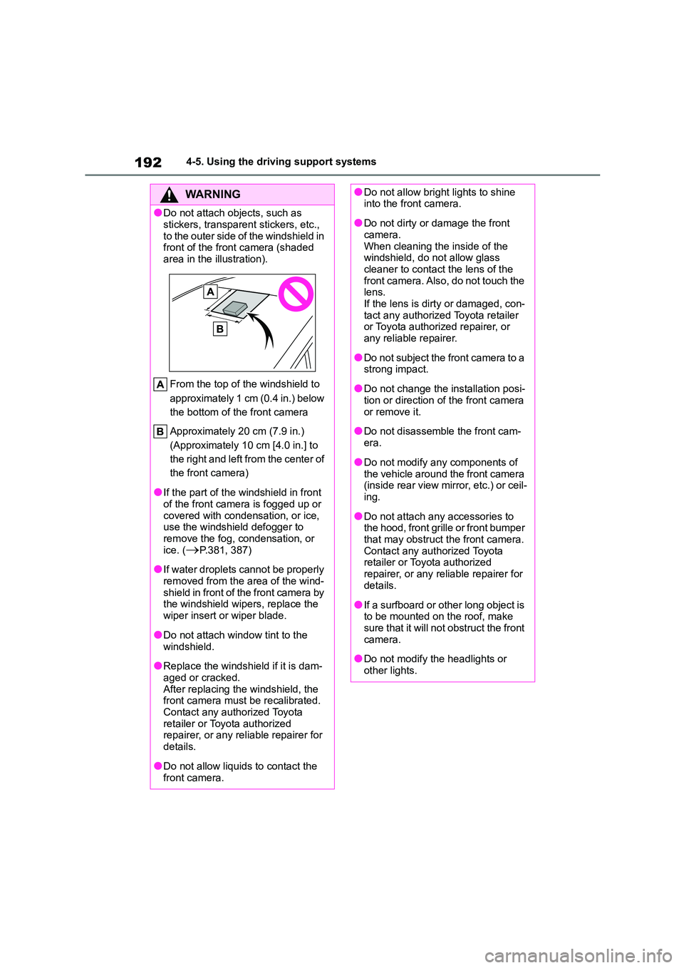
●Do not attach objects, such as
stickers, transparent stickers, etc.,
to the outer side of the windshield in front of the front camera (shaded
area in the illustration).
From the top of the windshield to
approximately 1 cm (0.4 in.) below
the bottom of the front camera
Approximately 20 cm (7.9 in.)
(Approximately 10 cm [4.0 in.] to
the right and left from the center of
the front camera)
●If the part of the windshield in front
of the front camera is fogged up or
covered with condensation, or ice, use the windshield defogger to
remove the fog, condensation, or
ice. (P.381, 387)
●If water droplets cannot be properly
removed from the area of the wind- shield in front of the front camera by
the windshield wipers, replace the
wiper insert or wiper blade.
●Do not attach window tint to the
windshield.
●Replace the windshield if it is dam-
aged or cracked. After replacing the windshield, the
front camera must be recalibrated.
Contact any authorized Toyota retailer or Toyota authorized
repairer, or any reliable repairer for
details.
●Do not allow liquids to contact the
front camera.
●Do not allow bright lights to shine into the front camera.
●Do not dirty or damage the front camera.
When cleaning the inside of the
windshield, do not allow glass cleaner to contact the lens of the
front camera. Also, do not touch the
lens. If the lens is dirty or damaged, con-
tact any authorized Toyota retailer
or Toyota authorized repairer, or any reliable repairer.
●Do not subject the front camera to a strong impact.
●Do not change the installation posi-tion or direction of the front camera
or remove it.
●Do not disassemble the front cam-
era.
●Do not modify any components of
the vehicle around the front camera
(inside rear view mirror, etc.) or ceil- ing.
●Do not attach any accessories to the hood, front grille or front bumper
that may obstruct the front camera.
Contact any authorized Toyota retailer or Toyota authorized
repairer, or any reliable repairer for
details.
●If a surfboard or other long object is
to be mounted on the roof, make sure that it will not obstruct the front
camera.
●Do not modify the headlights or
other lights.
Page 260 of 678
2584-5. Using the driving support systems
●The vehicle is driven in a country with
a different direction of traffic.
●The navigation system map data is
outdated.
●The navigation system is not operat-
ing.
●The speed information displayed on
the meter and on the navigation sys- tem may be different due to the navi-
gation system us ing map data.
■Speed limit sign display
If the engine switch was last turned off while a speed limit sign was displayed
on the multi-information display, the
same sign displays again when the engine switch is turned to ON.
■If “RSA Malfunction Visit Your
Dealer” is shown
The system may be malfunctioning. Have the vehicle inspected by any
authorized Toyota retailer or Toyota
authorized repairer, or any reliable repairer.
■Customization
Some functions can be customized.
( P.538)
*: If equipped
BSM (Blind Spot Moni-
tor)*
The Blind Spot Monitor is a
system that uses rear side
radar sensors installed on the
inner side of the rear bumper
on the left and right side to
assist the driver in confirming
safety when changing lanes.
WA R N I N G
■Cautions regarding the use of the system
The driver is solely responsible for
safe driving. Always drive safely, tak- ing care to observe your
surroundings.
The Blind Spot Monitor is a supple- mentary function which alerts the
driver that a vehicle is in a blind spot
of the outside rear view mirrors or is approaching rapidly from behind into
a blind spot. Do not overly rely on the
Blind Spot Monitor. As the function cannot judge if it is safe to change
lanes, over reliance could lead to an
accident resulting in death or serious injury.
As the system may not function cor-
rectly under certain conditions, the driver’s own visual confirmation of
safety is necessary.
Page 261 of 678
259
4
4-5. Using the driving support systems
Driving
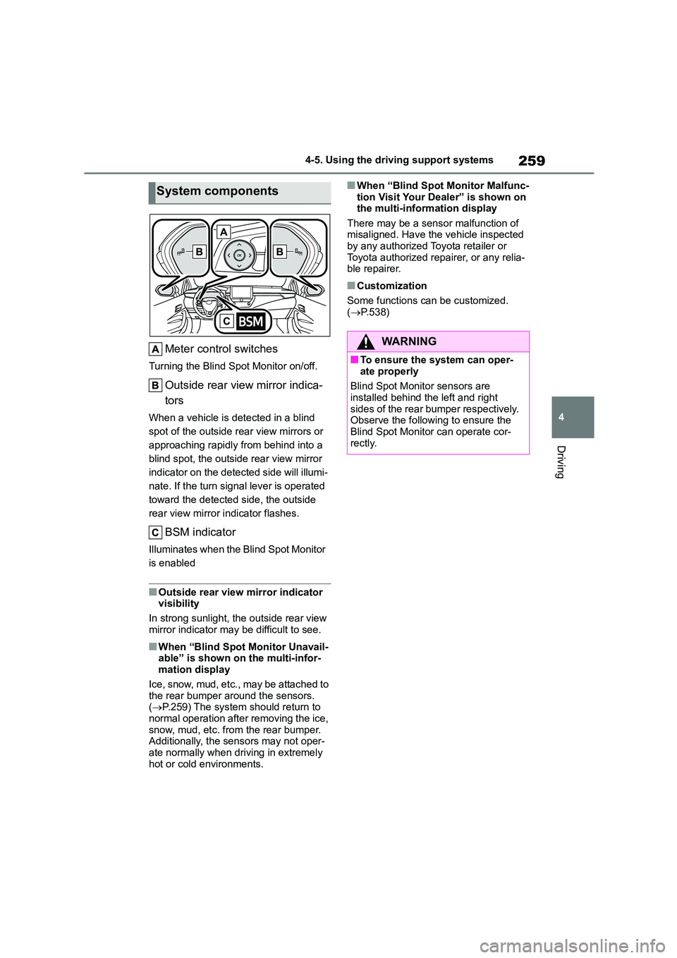
Meter control switches
Turning the Blind Spot Monitor on/off.
Outside rear view mirror indica-
tors
When a vehicle is detected in a blind
spot of the outside rear view mirrors or
approaching rapidly from behind into a
blind spot, the outside rear view mirror
indicator on the detected side will illumi-
nate. If the turn signal lever is operated
toward the detected side, the outside
rear view mirror indicator flashes.
BSM indicator
Illuminates when the Blind Spot Monitor
is enabled
■Outside rear view mirror indicator visibility
In strong sunlight, the outside rear view
mirror indicator may be difficult to see.
■When “Blind Spot Monitor Unavail- able” is shown on the multi-infor-
mation display
Ice, snow, mud, etc., may be attached to the rear bumper around the sensors.
( P.259) The system should return to
normal operation after removing the ice,
snow, mud, etc. from the rear bumper. Additionally, the sensors may not oper-
ate normally when driving in extremely
hot or cold environments.
■When “Blind Spot Monitor Malfunc-
tion Visit Your Dealer” is shown on the multi-information display
There may be a sensor malfunction of
misaligned. Have the vehicle inspected by any authorized Toyota retailer or
Toyota authorized repairer, or any relia-
ble repairer.
■Customization
Some functions can be customized.
( P.538)
System components
WA R N I N G
■To ensure the system can oper-
ate properly
Blind Spot Monitor sensors are
installed behind the left and right
sides of the rear bumper respectively. Observe the following to ensure the
Blind Spot Monitor can operate cor-
rectly.
Page 263 of 678
261
4
4-5. Using the driving support systems
Driving
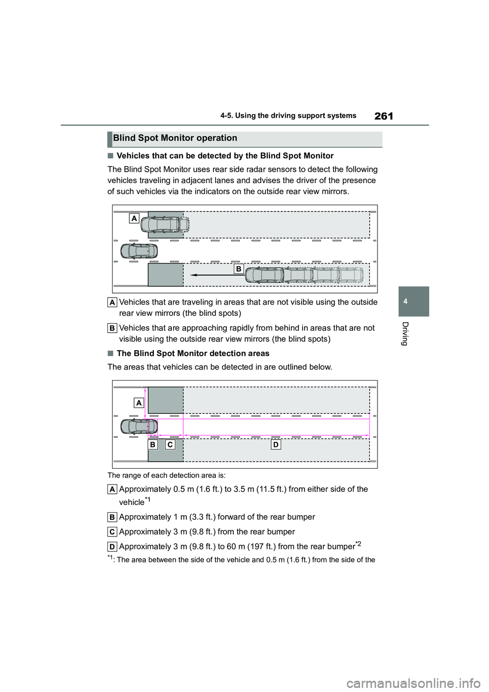
■Vehicles that can be detected by the Blind Spot Monitor
The Blind Spot Monitor uses rear side radar sensors to detect the following
vehicles traveling in adjacent lanes and advises the driver of the presence
of such vehicles via the indicators on the outside rear view mirrors.
Vehicles that are traveling in areas that are not visible using the outside
rear view mirrors (the blind spots)
Vehicles that are approaching rapidl y from behind in areas that are not
visible using the outside rear view mirrors (the blind spots)
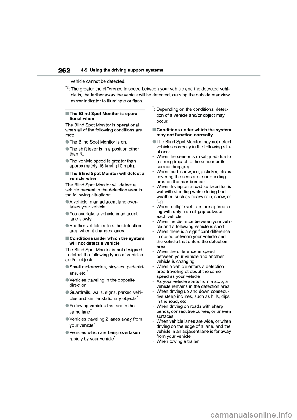
■The Blind Spot Monitor detection areas
The areas that vehicles can be detected in are outlined below.
The range of each detection area is:
Approximately 0.5 m (1.6 ft.) to 3.5 m (11.5 ft.) from either side of the
vehicle*1
Approximately 1 m (3.3 ft.) forward of the rear bumper
Approximately 3 m (9.8 ft.) from the rear bumper
Approximately 3 m (9.8 ft.) to 60 m (197 ft.) from the rear bumper*2
*1: The area between the side of the vehicle and 0.5 m (1.6 ft.) from the side of the
Blind Spot Monitor operation
Page 264 of 678
2624-5. Using the driving support systems
vehicle cannot be detected.
*2: The greater the difference in speed between your vehicle and the detected vehi-
cle is, the farther away the vehicle will be detected, causing the outside rear view
mirror indicator to illuminate or flash.
■The Blind Spot Monitor is opera-
tional when
The Blind Spot Monitor is operational
when all of the following conditions are
met:
●The Blind Spot Monitor is on.
●The shift lever is in a position other
than R.
●The vehicle speed is greater than
approximately 16 km/h (10 mph).
■The Blind Spot Monitor will detect a
vehicle when
The Blind Spot Monitor will detect a
vehicle present in the detection area in
the following situations:
●A vehicle in an adjacent lane over-
takes your vehicle.
●You overtake a vehicle in adjacent
lane slowly.
●Another vehicle enters the detection
area when it changes lanes.
■Conditions under which the system will not detect a vehicle
The Blind Spot Monitor is not designed
to detect the following types of vehicles
and/or objects:
●Small motorcycles, bicycles, pedestri-
ans, etc.*
●Vehicles traveling in the opposite
direction
●Guardrails, walls, signs, parked vehi-
cles and similar stationary objects*
●Following vehicles that are in the
same lane*
●Vehicles traveling 2 lanes away from
your vehicle*
●Vehicles which are being overtaken
rapidly by your vehicle*
*: Depending on the conditions, detec-
tion of a vehicle and/or object may
occur.
■Conditions under which the system may not function correctly
●The Blind Spot Monitor may not detect vehicles correctly in the following situ-
ations:
• When the sensor is misaligned due to a strong impact to the sensor or its
surrounding area
• When mud, snow, ice, a sticker, etc. is covering the sensor or surrounding
area on the rear bumper
• When driving on a road surface that is wet with standing water during bad
weather, such as heavy rain, snow, or
fog • When multiple vehicles are approach-
ing with only a small gap between
each vehicle • When the distance between your vehi-
cle and a following vehicle is short
• When there is a significant difference in speed between your vehicle and
the vehicle that enters the detection
area • When the difference in speed
between your vehicle and another
vehicle is changing • When a vehicle enters a detection
area traveling at about the same
speed as your vehicle • As your vehicle starts from a stop, a
vehicle remains in the detection area
• When driving up and down consecu-
tive steep inclines, such as hills, dips in the road, etc.
• When driving on roads with sharp
bends, consecutive curves, or uneven surfaces
• When vehicle lanes are wide, or when
driving on the edge of a lane, and the vehicle in an adjacent lane is far away
from your vehicle
• When towing a trailer
Page 274 of 678
2724-5. Using the driving support systems
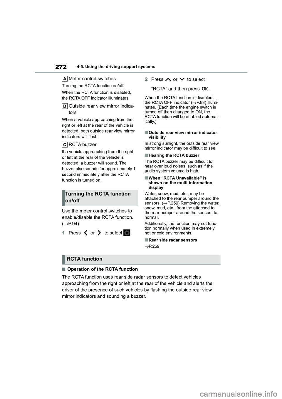
Meter control switches
Turning the RCTA function on/off.
When the RCTA function is disabled,
the RCTA OFF indicator illuminates.
Outside rear view mirror indica-
tors
When a vehicle approaching from the
right or left at the rear of the vehicle is
detected, both outside rear view mirror
indicators will flash.
RCTA buzzer
If a vehicle approaching from the right
or left at the rear of the vehicle is
detected, a buzzer will sound. The
buzzer also sounds for approximately 1
second immediately after the RCTA
function is turned on.
Use the meter control switches to
enable/disable the RCTA function.
( P. 9 4 )
1 Press or to select .
2 Press or to select
“RCTA” and then press .
When the RCTA function is disabled, the RCTA OFF indicator ( P.83) illumi-
nates. (Each time the engine switch is
turned off then changed to ON, the RCTA function will be enabled automat-
ically.)
■Outside rear view mirror indicator visibility
In strong sunlight, the outside rear view
mirror indicator may be difficult to see.
■Hearing the RCTA buzzer
The RCTA buzzer may be difficult to
hear over loud noises, such as if the
audio system volume is high.
■When “RCTA Unavailable” is shown on the multi-information
display
Water, snow, mud, etc., may be attached to the rear bumper around the
sensors. ( P.259) Removing the water,
snow, mud, etc., from the attached to the rear bumper around the sensors to
normal.
Additionally, the function may not func-
tion normally when used in extremely hot or cold environments.
■Rear side radar sensors
P. 2 5 9
■Operation of the RCTA function
The RCTA function uses rear side radar sensors to detect vehicles
approaching from the right or left at the rear of the vehicle and alerts the
driver of the presence of such vehicles by flashing the outside rear view
mirror indicators and sounding a buzzer.
Turning the RCTA function
on/off
RCTA function
Page 297 of 678
295
4
4-5. Using the driving support systems
Driving
slowly proceed forward while
adjusting your speed by
depressing the brake pedal.
9 When a level beep is emitted
and the stop display ( P.290) is
shown on the display, stop the
vehicle.
10 Change the shift lever to R.
11 Assume an ordinary posture for
backing up, rest your hands
lightly on the steering wheel
without applying any force,
directly confirm the safety of the
area to the rear and around the
vehicle slowly back up while
adjusting your speed by
depressing the brake pedal.
Depending on the condition of the park-
ing space, steps 6 to 11 may need to be repeated.
12 When the vehicle is almost
entirely within the target parking
spot, a high-pitched beep is
emitted and the stop display is
shown on the display, stop the
vehicle.
This completes th e parallel parking assist mode.
After stopping, feel free to
maneuver the vehicle to reach
the desired parking spot.
Be sure to back up while check-
ing the area to the front and rear
of the vehicle directly and by
using the mirrors.
■Parallel parking assist mode oper-
ating conditions
●In order to operate the parallel parking
assist mode correctly, drive slowly (at
a speed at which the vehicle can be quickly stopped) parallel to the road
(or shoulder) while maintaining a dis-
tance of approximately 1 m (3.3 ft.) to any parked vehicles.
●The function cannot be used when the vehicle speed is approximately 30
km/h (19 mph) or higher.
●The front side sensors and rear side
sensors are used to detect parked
vehicles and determine the parking spot. Therefore, when detection is not
possible ( P.311), guidance is not
issued.
●If there are no parked vehicles, the
parking spot cannot be determined. Therefore, the parallel parking assist
mode cannot be operated.
●If unable to detect the environment
surrounding the parking space, the
parallel parking assist mode may not be able to operate.
●Guidance will continue until the vehi-cle speed meets or exceeds approxi-
mately 30 km/h (19 mph) or the
function is turned off using the S-IPA switch.
■Timing for pressing the S-IPA
switch
In the following cases, the assist mode may also operate during the steps taken
to park using the parallel parking assist
mode. However, in th ese cases, conduct parking procedures according to the
information on the mu lti-information dis-
play.
●In step 1the S-IPA switch is pressed
after already passing over the target parking spot.
If the vehicle is not stopped in step 1,
pressing the S-IPA switch 1 time while
the vehicle is in motion allows you to select “Parallel Parking” and proceed
directly to step 2.
●The vehicle is moved up to the posi-
tion in step 3 without the S-IPA switch
being pressed. Then the S-IPA switch is pressed after having changed the
Page 306 of 678
3044-5. Using the driving support systems
while adjusting your speed by
depressing the brake pedal, to
reach the desired parking spot.
Be sure to back up while check-
ing the area to the front and rear
of the vehicle directly and by
using the mirrors.
■Back-in parking assist mode oper-
ating conditions
●In order to operate the function cor-
rectly, drive slowly (at a speed at which the vehicle can be quickly
stopped). Come to a full stop so that
the center of the parking space is nearly perpendicular to the vehicle,
and then operate the S-IPA switch.
●The function cannot be used when the
vehicle speed is approximately 30
km/h (19 mph) or higher.
●The front side sensors and rear side
sensors are used to detect parked vehicles and determine the parking
spot. Therefore, when detection is not
possible ( P.311), guidance is not issued.
●If there are no parked vehicles, the parking spot cannot be determined.
Therefore, the back-in parking assist
mode cannot be operated.
●If unable to detect the environment
surrounding the parking space, the
back-in parking assist mode may not be able to operate.
●Depending on the condition of the parking space, if there is not enough
space in front of the vehicle required
to perform the parking operation, the target parking spot may not be reach-
able.
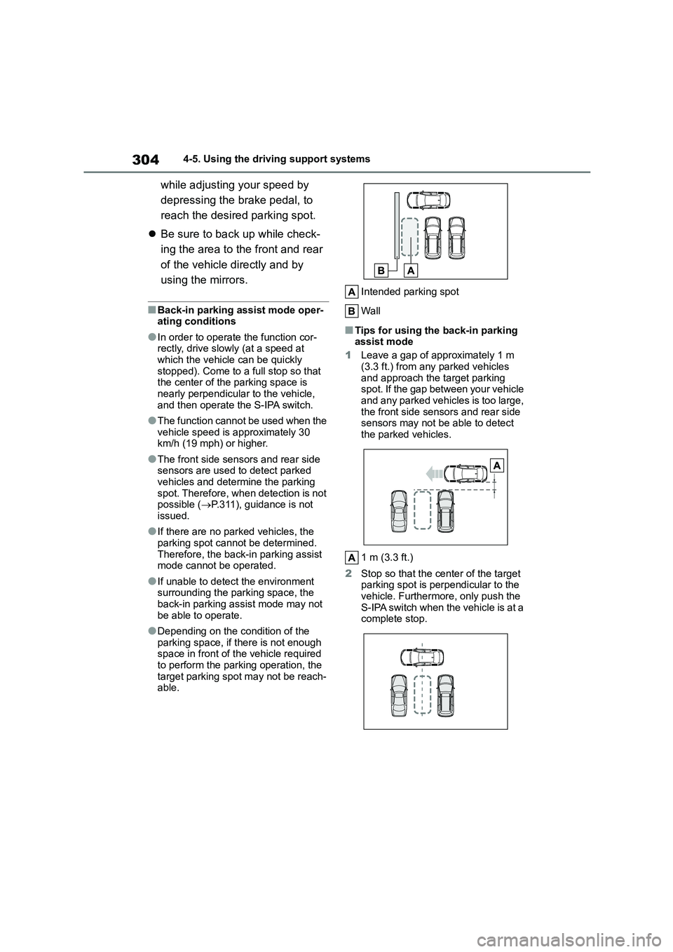
Intended parking spot
Wall
■Tips for using the back-in parking assist mode
1 Leave a gap of approximately 1 m
(3.3 ft.) from any parked vehicles
and approach the target parking spot. If the gap between your vehicle
and any parked vehicles is too large,
the front side sensors and rear side sensors may not be able to detect
the parked vehicles.
1 m (3.3 ft.)
2 Stop so that the center of the target parking spot is perpendicular to the
vehicle. Furthermore, only push the
S-IPA switch when the vehicle is at a complete stop.
Page 313 of 678
311
4
4-5. Using the driving support systems
Driving
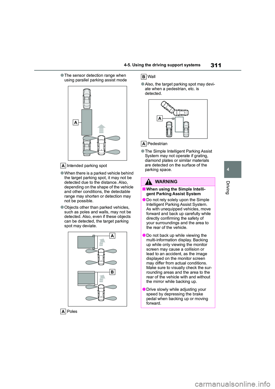
●The sensor detection range when
using parallel parking assist mode
Intended parking spot
●When there is a parked vehicle behind
the target parking spot, it may not be
detected due to the distance. Also, depending on the shape of the vehicle
and other conditions, the detectable
range may shorten or detection may not be possible.
●Objects other than parked vehicles, such as poles and walls, may not be
detected. Also, even if these objects
can be detected, the target parking spot may deviate.
Poles
Wall
●Also, the target parking spot may devi- ate when a pedestrian, etc. is
detected.
Pedestrian
●The Simple Intelligent Parking Assist
System may not operate if grating, diamond plates or similar materials
are detected on the surface of the
parking space.
WA R N I N G
■When using the Simple Intelli- gent Parking Assist System
●Do not rely solely upon the Simple
Intelligent Parking Assist System. As with unequipped vehicles, move
forward and back up carefully while
directly confirming the safety of your surroundings and the area to
the rear of the vehicle.
●Do not back up while viewing the
multi-information display. Backing
up while only viewing the monitor screen may cause a collision or
lead to an accident, as the image
displayed on the monitor screen may differ from actual conditions.
Make sure to visually check the sur-
rounding areas and the area to the rear of the vehicle with and without
the mirror while backing up.
●Drive slowly while adjusting your
speed by depressing the brake
pedal when backing up or moving forward.
Page 382 of 678
3806-1. Using the air conditioning system and defogger
6-1.Using the air conditioning system and defogger
*: If equipped
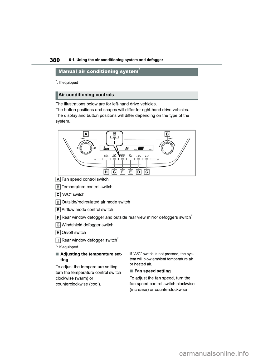
The illustrations below are for left-hand drive vehicles.
The button positions and shapes will differ for right-hand drive vehicles.
The display and button positions will di ffer depending on the type of the
system.
Fan speed control switch
Temperature control switch
“A/C” switch
Outside/recirculated air mode switch
Airflow mode control switch
Rear window defogger and outside rear view mirror defoggers switch*
Windshield defogger switch
On/off switch
Rear window defogger switch*
*: If equipped
■Adjusting the temperature set-
ting
To adjust the temperature setting,
turn the temperature control switch
clockwise (warm) or
counterclockwise (cool).
If “A/C” switch is not pressed, the sys-
tem will blow ambient temperature air
or heated air.
■Fan speed setting
To adjust the fan speed, turn the
fan speed control switch clockwise
(increase) or counterclockwise
Manual air conditioning system*
Air conditioning controls