sensor TOYOTA COROLLA 2022 (in English) Owner's Guide
[x] Cancel search | Manufacturer: TOYOTA, Model Year: 2022, Model line: COROLLA, Model: TOYOTA COROLLA 2022Pages: 678, PDF Size: 147.24 MB
Page 241 of 678
239
4
4-5. Using the driving support systems
Driving
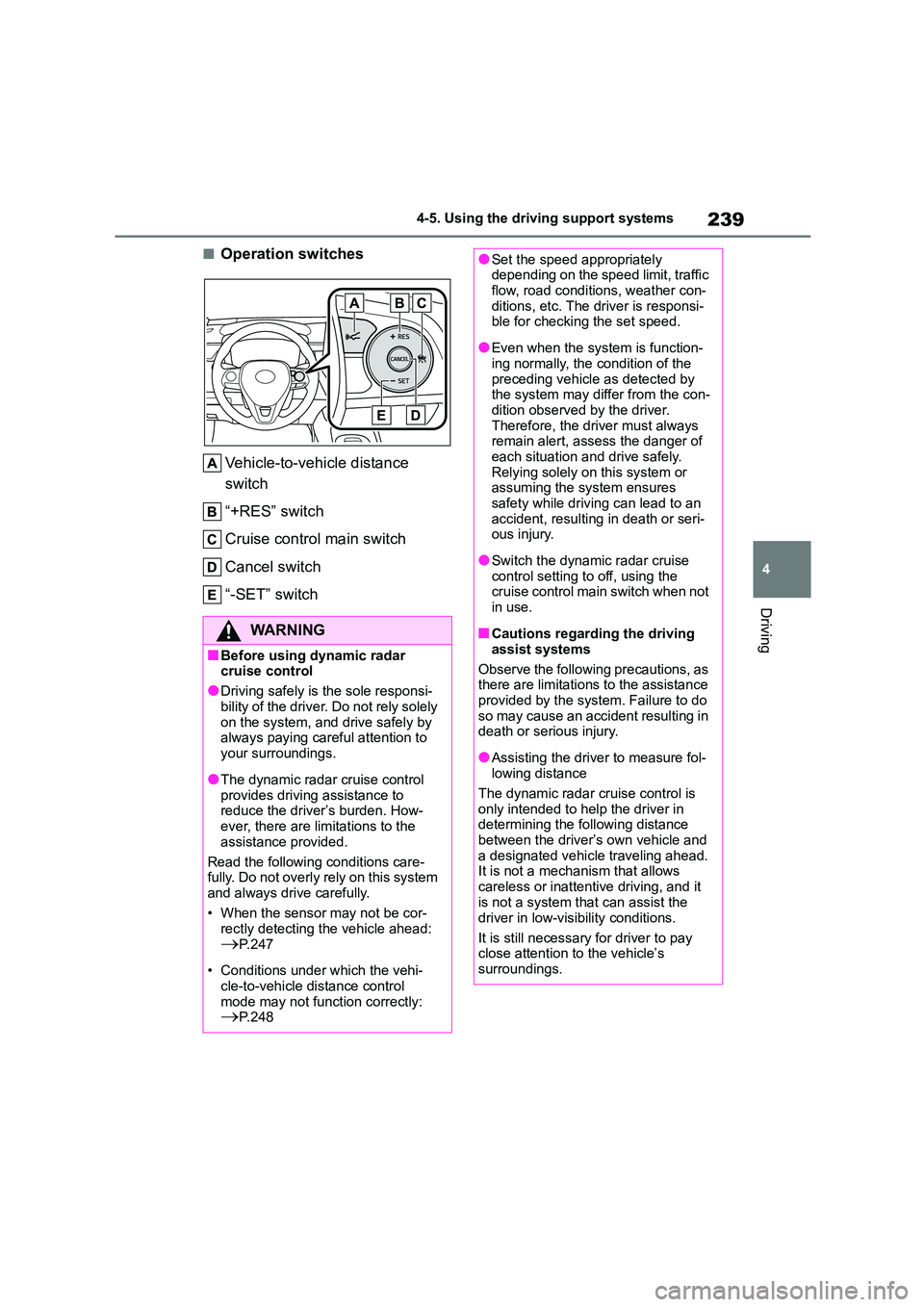
■Operation switches
Vehicle-to-vehicle distance
switch
“+RES” switch
Cruise control main switch
Cancel switch
“-SET” switch
WA R N I N G
■Before using dynamic radar cruise control
●Driving safely is the sole responsi-
bility of the driver. Do not rely solely on the system, and drive safely by
always paying careful attention to
your surroundings.
●The dynamic radar cruise control
provides driving assistance to reduce the driver’s burden. How-
ever, there are limitations to the
assistance provided.
Read the following conditions care-
fully. Do not overly rely on this system
and always drive carefully.
• When the sensor may not be cor-
rectly detecting the vehicle ahead:
P. 2 4 7
• Conditions under which the vehi-
cle-to-vehicle distance control mode may not function correctly:
P. 2 4 8
●Set the speed appropriately depending on the speed limit, traffic
flow, road conditions, weather con-
ditions, etc. The driver is responsi- ble for checking the set speed.
●Even when the system is function-ing normally, the condition of the
preceding vehicle as detected by
the system may differ from the con- dition observed by the driver.
Therefore, the driver must always
remain alert, assess the danger of each situation and drive safely.
Relying solely on this system or
assuming the system ensures safety while driving can lead to an
accident, resulting in death or seri-
ous injury.
●Switch the dynamic radar cruise
control setting to off, using the cruise control main switch when not
in use.
■Cautions regarding the driving
assist systems
Observe the following precautions, as there are limitations to the assistance
provided by the system. Failure to do
so may cause an accident resulting in death or serious injury.
●Assisting the driver to measure fol-lowing distance
The dynamic radar cruise control is
only intended to help the driver in determining the following distance
between the driver’s own vehicle and
a designated vehicle traveling ahead. It is not a mechanism that allows
careless or inattentive driving, and it
is not a system that can assist the
driver in low-visibility conditions.
It is still necessary for driver to pay
close attention to the vehicle’s
surroundings.
Page 242 of 678
2404-5. Using the driving support systems
WA R N I N G
●Assisting the driver to judge proper
following distance
The dynamic radar cruise control determines whether the following dis-
tance between the driver’s own vehi-
cle and a designated vehicle traveling ahead is within a set range. It is not
capable of making any other type of
judgement. Therefore, it is absolutely
necessary for the driver to remain vig- ilant and to determine whether or not
there is a possibility of danger in any
given situation.
●Assisting the driver to operate the
vehicle
The dynamic radar cruise control
does not include functions which will
prevent or avoid collisions with vehi- cles ahead of your vehicle. Therefore,
if there is ever any possibility of dan-
ger, the driver must take immediate and direct control of the vehicle and
act appropriately in order to ensure
the safety of all involved.
■Situations unsuitable for
dynamic radar cruise control
Do not use dynamic radar cruise con-
trol in any of the following situations.
Doing so may result in inappropriate speed control and could cause an
accident resulting in death or serious
injury.
●Roads where there are pedestrians,
cyclists, etc.
●In heavy traffic
●On roads with sharp bends
●On winding roads
●On slippery roads, such as those
covered with rain, ice or snow
●On steep downhills, or where there are sudden changes between sharp
up and down gradients
Vehicle speed may exceed the set speed when driving down a steep hill.
●At entrances to freeways and high-ways
●When weather conditions are bad enough that they may prevent the
sensors from detecting correctly
(fog, snow, sandstorm, heavy rain, etc.)
●When there is rain, snow, etc. on the front surface of the radar or
front camera
●In traffic conditions that require fre-
quent repeated acceleration and
deceleration
●When your vehicle is towing a
trailer or during emergency towing
●When an approach warning buzzer
is heard often
Page 248 of 678
2464-5. Using the driving support systems
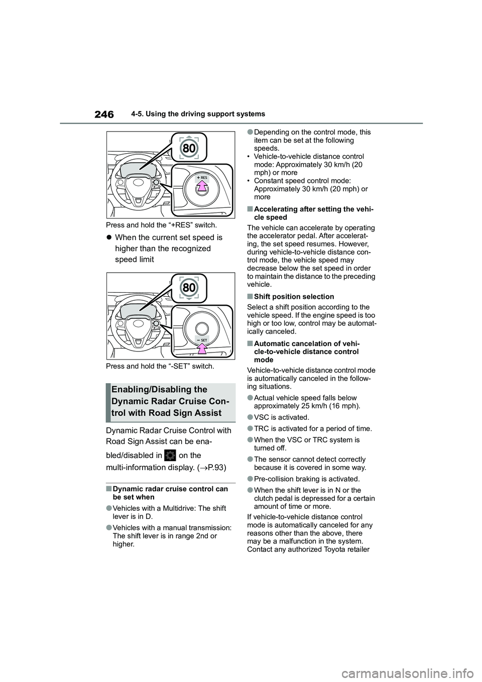
Press and hold the “+RES” switch.
When the current set speed is
higher than the recognized
speed limit
Press and hold the “-SET” switch.
Dynamic Radar Cruise Control with
Road Sign Assist can be ena-
bled/disabled in on the
multi-information display. ( P. 9 3 )
■Dynamic radar cruise control can be set when
●Vehicles with a Multidrive: The shift lever is in D.
●Vehicles with a manual transmission:
The shift lever is in range 2nd or higher.
●Depending on the control mode, this
item can be set at the following speeds.
• Vehicle-to-vehicle distance control
mode: Approximately 30 km/h (20 mph) or more
• Constant speed control mode:
Approximately 30 km/h (20 mph) or more
■Accelerating after setting the vehi-
cle speed
The vehicle can accelerate by operating the accelerator pedal. After accelerat-
ing, the set speed resumes. However,
during vehicle-to-vehicle distance con- trol mode, the vehicle speed may
decrease below the set speed in order
to maintain the distance to the preceding vehicle.
■Shift position selection
Select a shift positi on according to the
vehicle speed. If the engine speed is too high or too low, control may be automat-
ically canceled.
■Automatic cancelation of vehi-
cle-to-vehicle distance control mode
Vehicle-to-vehicle distance control mode
is automatically canceled in the follow- ing situations.
●Actual vehicle speed falls below approximately 25 km/h (16 mph).
●VSC is activated.
●TRC is activated for a period of time.
●When the VSC or TRC system is
turned off.
●The sensor cannot detect correctly
because it is covered in some way.
●Pre-collision braking is activated.
●When the shift lever is in N or the
clutch pedal is depressed for a certain amount of time or more.
If vehicle-to-vehicle distance control
mode is automatically canceled for any reasons other than the above, there
may be a malfunction in the system.
Contact any authorized Toyota retailer
Enabling/Disabling the
Dynamic Radar Cruise Con-
trol with Road Sign Assist
Page 249 of 678
247
4
4-5. Using the driving support systems
Driving
or Toyota authorized repairer, or any reli-
able repairer.
■Automatic cancelation of constant speed control mode
Constant speed control mode is auto-
matically canceled in the following situa- tions:
●Actual vehicle speed is more than approximately 16 km/h (10 mph)
below the set vehicle speed.
●Actual vehicle speed falls below
approximately 30 km/h (20 mph).
●VSC is activated.
●TRC is activated for a period of time.
●When the VSC or TRC system is
turned off.
●Pre-collision braking is activated.
●When the shift lever is in N or the
clutch pedal is depressed for a certain
amount of time or more.
If constant speed control mode is auto-
matically canceled for any reasons other
than the above, there may be a malfunc- tion in the system. Contact any author-
ized Toyota retailer or Toyota authorized
repairer, or any reliable repairer.
■The Dynamic Radar Cruise Control with Road Sign Assist may not
operate properly when
As the Dynamic Radar Cruise Control with Road Sign Assist may not operate
properly in conditions in which RSA may
not operate or detect correctly ( P.257), when using this function,
make sure to check the speed limit sign
displayed.
In the following situations, the set speed
may not be changed to the recognized
speed limit by pressing and holding the
“+RES”/“-SET” switch.
●If speed limit information is not availa-
ble
●When the recognized speed limit is
the same as the set speed
●When the recognized speed limit is
outside of the speed range that the
dynamic radar cruise control system
can operate
■Brake operation
A brake operation sound may be heard
and the brake pedal response may
change, but these are not malfunctions.
■Warning messages and buzzers for dynamic radar cruise control
Warning messages and buzzers are
used to indicate a system malfunction or to inform the driver of the need for cau-
tion while driving. If a warning message
is shown on the multi-information dis- play, read the message and follow the
instructions. ( P.200, 480)
■When the sensor may not be cor-
rectly detecting the vehicle ahead
In the case of the following and depend-
ing on the conditions, operate the brake
pedal when deceleration of the system is insufficient or operate the accelerator
pedal when acceleration is required.
As the sensor may not be able to cor- rectly detect these types of vehicles, the
approach warning ( P.244) may not be
activated.
●Vehicles that cut in suddenly
●Vehicles traveling at low speeds
●Vehicles that are not moving in the same lane
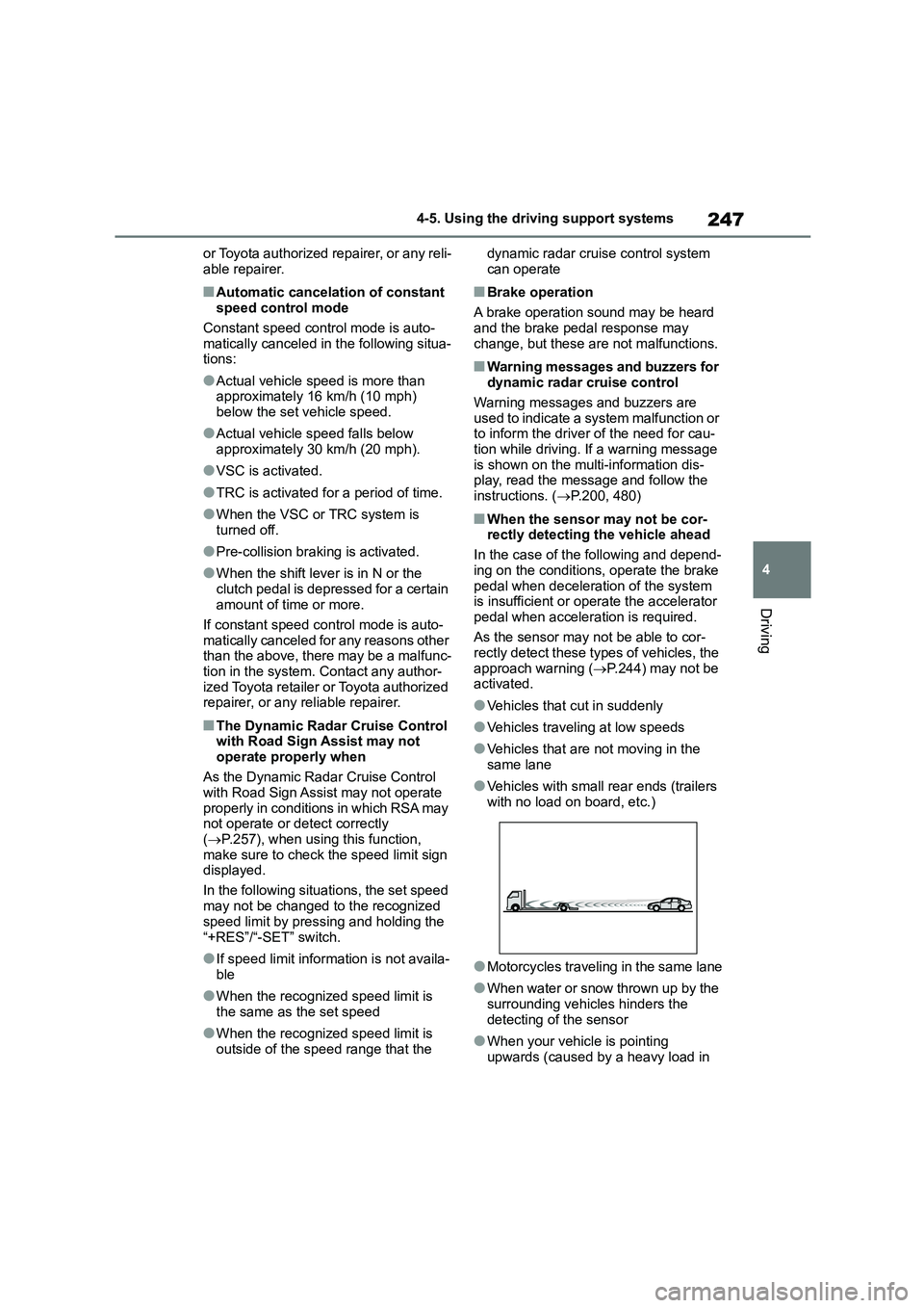
●Vehicles with small rear ends (trailers with no load on board, etc.)
●Motorcycles traveling in the same lane
●When water or snow thrown up by the
surrounding vehicles hinders the
detecting of the sensor
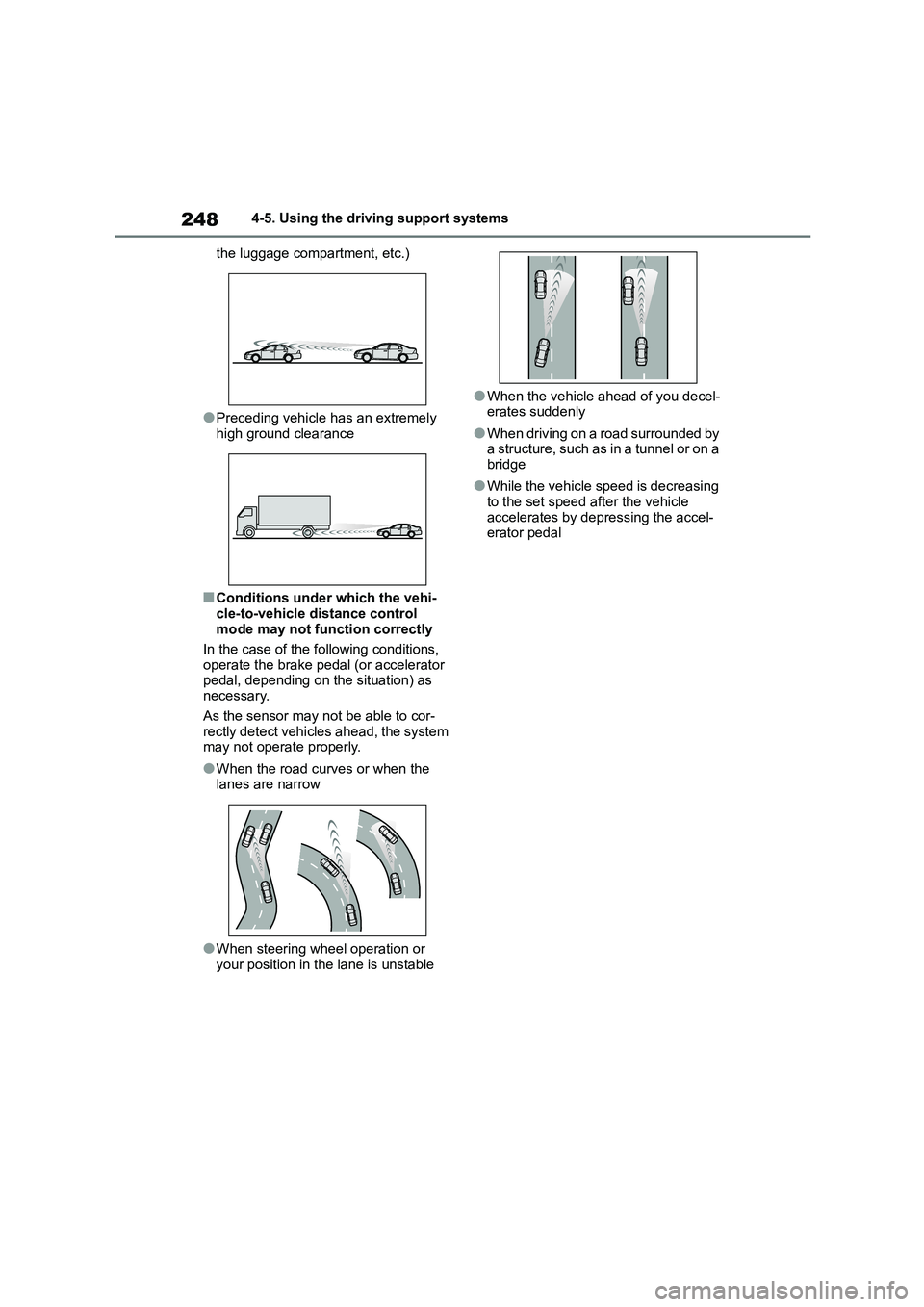
●When your vehicle is pointing
upwards (caused by a heavy load in
Page 250 of 678
2484-5. Using the driving support systems
the luggage compartment, etc.)
●Preceding vehicle has an extremely
high ground clearance
■Conditions under which the vehi-
cle-to-vehicle distance control
mode may not function correctly
In the case of the following conditions,
operate the brake pedal (or accelerator
pedal, depending on the situation) as necessary.
As the sensor may not be able to cor-
rectly detect vehicles ahead, the system may not operate properly.
●When the road curves or when the lanes are narrow
●When steering wheel operation or your position in the lane is unstable
●When the vehicle ahead of you decel-
erates suddenly
●When driving on a road surrounded by
a structure, such as in a tunnel or on a bridge
●While the vehicle speed is decreasing to the set speed after the vehicle
accelerates by depr essing the accel-
erator pedal
Page 259 of 678
257
4
4-5. Using the driving support systems
Driving
the speed notification threshold
of the speed limit sign displayed,
the sign displa y will be empha-
sized and a buzzer will sound.
When the RSA system recog-
nizes a no-entry sign and detects
that the vehicle has entered a
no-entry area based on the map
information of the navigation sys-
tem, the no-entry sign flashes
and a buzzer will sound. (For
vehicles with navigation system)
If it is detected that your vehicle
is overtaking when a no overtak-
ing sign is displayed on the
multi-information display, the dis-
played sign will flash and a
buzzer will sound.
Depending on the situation, traffic
environment (traffic direction,
speed unit) may be detected incor-
rectly and a notification function
may not operate properly.
■Setting procedure
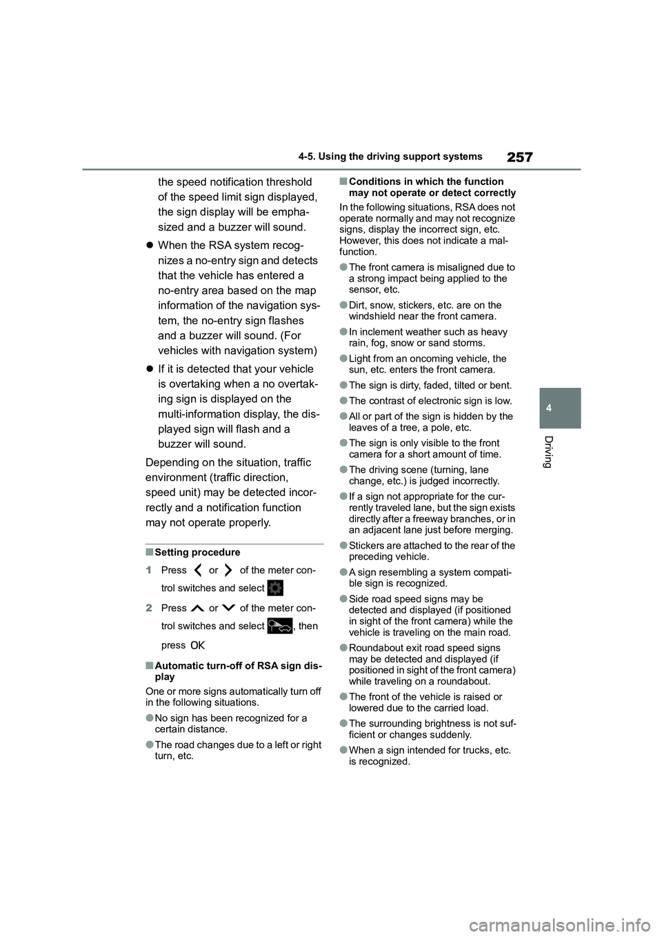
1 Press or of the meter con-
trol switches and select
2 Press or of the meter con-
trol switches and select , then
press
■Automatic turn-off of RSA sign dis-
play
One or more signs automatically turn off in the following situations.
●No sign has been recognized for a certain distance.
●The road changes due to a left or right turn, etc.
■Conditions in which the function
may not operate or detect correctly
In the following situations, RSA does not
operate normally and may not recognize
signs, display the incorrect sign, etc. However, this does not indicate a mal-
function.
●The front camera is misaligned due to
a strong impact being applied to the
sensor, etc.
●Dirt, snow, stickers, etc. are on the
windshield near the front camera.
●In inclement weather such as heavy
rain, fog, snow or sand storms.
●Light from an oncoming vehicle, the
sun, etc. enters the front camera.
●The sign is dirty, faded, tilted or bent.
●The contrast of electronic sign is low.
●All or part of the sign is hidden by the leaves of a tree, a pole, etc.
●The sign is only visible to the front camera for a short amount of time.
●The driving scene (turning, lane change, etc.) is judged incorrectly.
●If a sign not appropriate for the cur-rently traveled lane, but the sign exists
directly after a freeway branches, or in
an adjacent lane just before merging.
●Stickers are attached to the rear of the
preceding vehicle.
●A sign resembling a system compati-
ble sign is recognized.
●Side road speed signs may be
detected and displayed (if positioned in sight of the front camera) while the
vehicle is traveling on the main road.
●Roundabout exit road speed signs
may be detected and displayed (if
positioned in sight of the front camera)
while traveling on a roundabout.
●The front of the vehicle is raised or
lowered due to the carried load.
●The surrounding brightness is not suf-
ficient or changes suddenly.
●When a sign intended for trucks, etc.
is recognized.
Page 260 of 678

2584-5. Using the driving support systems
●The vehicle is driven in a country with
a different direction of traffic.
●The navigation system map data is
outdated.
●The navigation system is not operat-
ing.
●The speed information displayed on
the meter and on the navigation sys- tem may be different due to the navi-
gation system us ing map data.
■Speed limit sign display
If the engine switch was last turned off while a speed limit sign was displayed
on the multi-information display, the
same sign displays again when the engine switch is turned to ON.
■If “RSA Malfunction Visit Your
Dealer” is shown
The system may be malfunctioning. Have the vehicle inspected by any
authorized Toyota retailer or Toyota
authorized repairer, or any reliable repairer.
■Customization
Some functions can be customized.
( P.538)
*: If equipped
BSM (Blind Spot Moni-
tor)*
The Blind Spot Monitor is a
system that uses rear side
radar sensors installed on the
inner side of the rear bumper
on the left and right side to
assist the driver in confirming
safety when changing lanes.
WA R N I N G
■Cautions regarding the use of the system
The driver is solely responsible for
safe driving. Always drive safely, tak- ing care to observe your
surroundings.
The Blind Spot Monitor is a supple- mentary function which alerts the
driver that a vehicle is in a blind spot
of the outside rear view mirrors or is approaching rapidly from behind into
a blind spot. Do not overly rely on the
Blind Spot Monitor. As the function cannot judge if it is safe to change
lanes, over reliance could lead to an
accident resulting in death or serious injury.
As the system may not function cor-
rectly under certain conditions, the driver’s own visual confirmation of
safety is necessary.
Page 261 of 678
259
4
4-5. Using the driving support systems
Driving
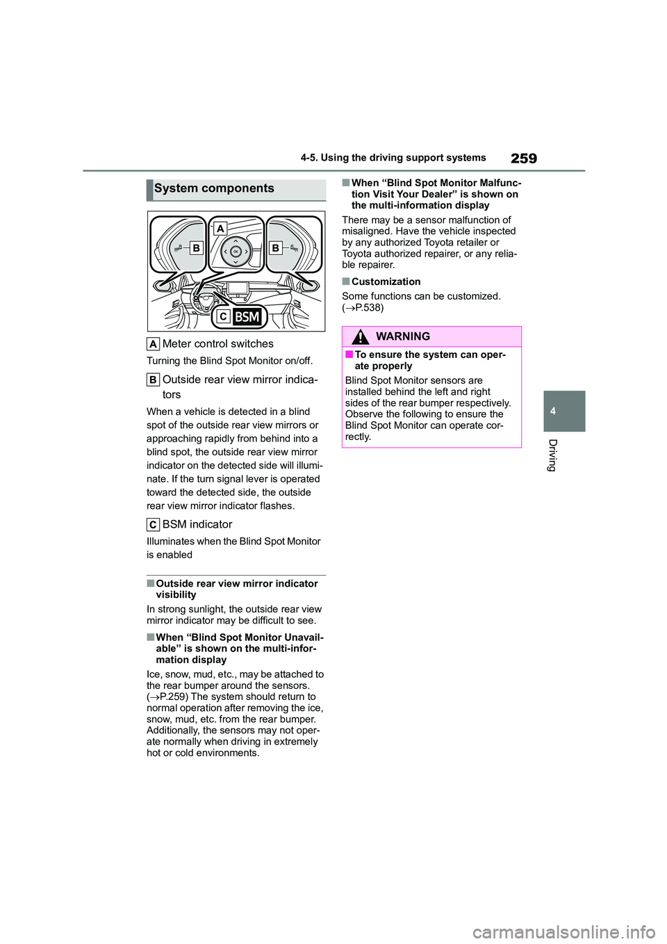
Meter control switches
Turning the Blind Spot Monitor on/off.
Outside rear view mirror indica-
tors
When a vehicle is detected in a blind
spot of the outside rear view mirrors or
approaching rapidly from behind into a
blind spot, the outside rear view mirror
indicator on the detected side will illumi-
nate. If the turn signal lever is operated
toward the detected side, the outside
rear view mirror indicator flashes.
BSM indicator
Illuminates when the Blind Spot Monitor
is enabled
■Outside rear view mirror indicator visibility
In strong sunlight, the outside rear view
mirror indicator may be difficult to see.
■When “Blind Spot Monitor Unavail- able” is shown on the multi-infor-
mation display
Ice, snow, mud, etc., may be attached to the rear bumper around the sensors.
( P.259) The system should return to
normal operation after removing the ice,
snow, mud, etc. from the rear bumper. Additionally, the sensors may not oper-
ate normally when driving in extremely
hot or cold environments.
■When “Blind Spot Monitor Malfunc-
tion Visit Your Dealer” is shown on the multi-information display
There may be a sensor malfunction of
misaligned. Have the vehicle inspected by any authorized Toyota retailer or
Toyota authorized repairer, or any relia-
ble repairer.
■Customization
Some functions can be customized.
( P.538)
System components
WA R N I N G
■To ensure the system can oper-
ate properly
Blind Spot Monitor sensors are
installed behind the left and right
sides of the rear bumper respectively. Observe the following to ensure the
Blind Spot Monitor can operate cor-
rectly.
Page 262 of 678
2604-5. Using the driving support systems
Use the meter control switches to
turn on/off the function.
1 Press or to select .
2 Press or to select
and then press .
WA R N I N G
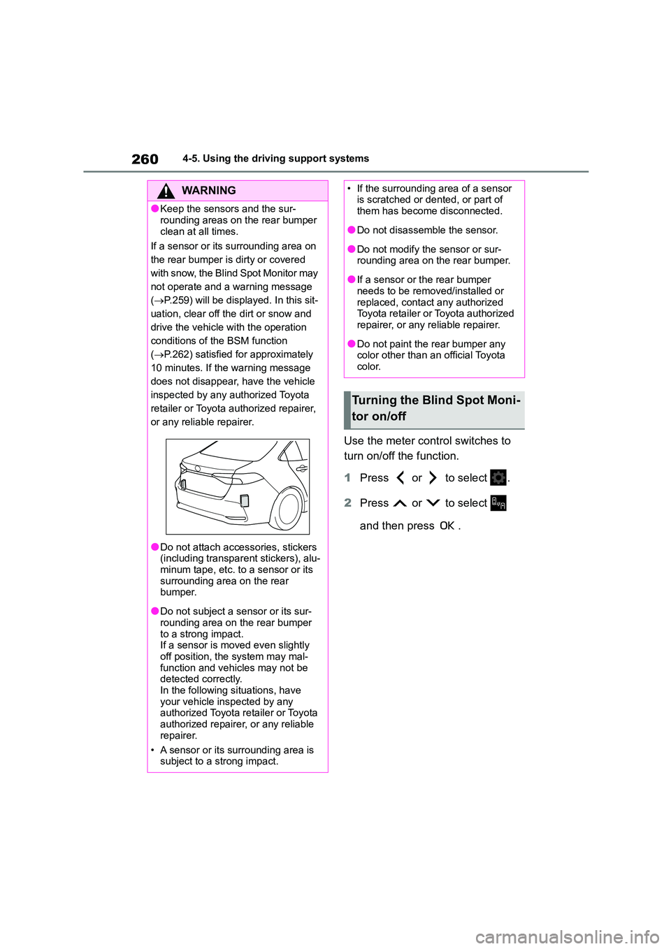
●Keep the sensors and the sur-
rounding areas on the rear bumper
clean at all times.
If a sensor or its surrounding area on
the rear bumper is dirty or covered
with snow, the Blind Spot Monitor may
not operate and a warning message
( P.259) will be displayed. In this sit-
uation, clear off the dirt or snow and
drive the vehicle with the operation
conditions of the BSM function
( P.262) satisfied for approximately
10 minutes. If the warning message
does not disappear, have the vehicle
inspected by any authorized Toyota
retailer or Toyota authorized repairer,
or any reliable repairer.
●Do not attach accessories, stickers
(including transparent stickers), alu-
minum tape, etc. to a sensor or its surrounding area on the rear
bumper.
●Do not subject a sensor or its sur-
rounding area on the rear bumper
to a strong impact. If a sensor is moved even slightly
off position, the system may mal-
function and vehicles may not be detected correctly.
In the following situations, have
your vehicle inspected by any authorized Toyota retailer or Toyota
authorized repairer, or any reliable
repairer.
• A sensor or its surrounding area is
subject to a strong impact.
• If the surrounding area of a sensor is scratched or dented, or part of
them has become disconnected.
●Do not disassemble the sensor.
●Do not modify the sensor or sur- rounding area on the rear bumper.
●If a sensor or the rear bumper needs to be removed/installed or
replaced, contact any authorized
Toyota retailer or Toyota authorized repairer, or any reliable repairer.
●Do not paint the rear bumper any color other than an official Toyota
color.
Turning the Blind Spot Moni-
tor on/off
Page 263 of 678
261
4
4-5. Using the driving support systems
Driving
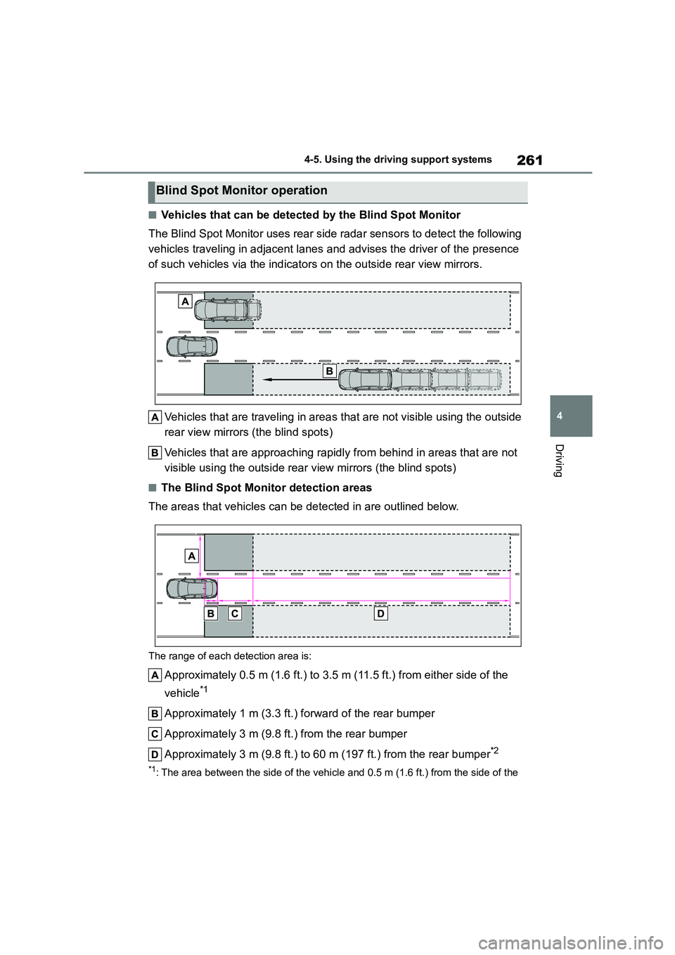
■Vehicles that can be detected by the Blind Spot Monitor
The Blind Spot Monitor uses rear side radar sensors to detect the following
vehicles traveling in adjacent lanes and advises the driver of the presence
of such vehicles via the indicators on the outside rear view mirrors.
Vehicles that are traveling in areas that are not visible using the outside
rear view mirrors (the blind spots)
Vehicles that are approaching rapidl y from behind in areas that are not
visible using the outside rear view mirrors (the blind spots)
■The Blind Spot Monitor detection areas
The areas that vehicles can be detected in are outlined below.
The range of each detection area is:
Approximately 0.5 m (1.6 ft.) to 3.5 m (11.5 ft.) from either side of the
vehicle*1
Approximately 1 m (3.3 ft.) forward of the rear bumper
Approximately 3 m (9.8 ft.) from the rear bumper
Approximately 3 m (9.8 ft.) to 60 m (197 ft.) from the rear bumper*2
*1: The area between the side of the vehicle and 0.5 m (1.6 ft.) from the side of the
Blind Spot Monitor operation