stop start TOYOTA COROLLA CROSS 2022 Owners Manual
[x] Cancel search | Manufacturer: TOYOTA, Model Year: 2022, Model line: COROLLA CROSS, Model: TOYOTA COROLLA CROSS 2022Pages: 612, PDF Size: 17.18 MB
Page 3 of 612
3TABLE OF CONTENTS
1
2
3
4
5
6
7
8
9
10
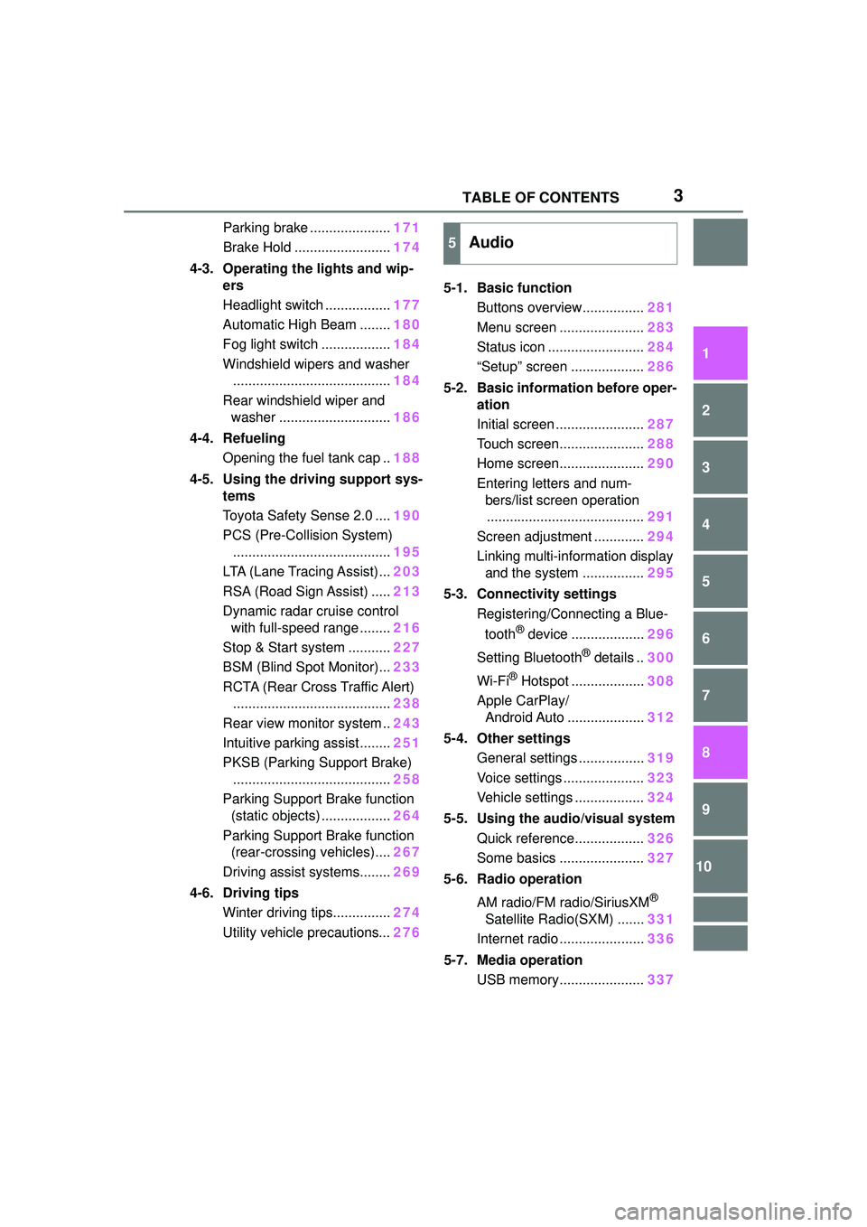
Parking brake .....................171
Brake Hold ......................... 174
4-3. Operating the lights and wip- ers
Headlight switch ................. 177
Automatic High Beam ........ 180
Fog light switch .................. 184
Windshield wipers and washer ......................................... 184
Rear windshield wiper and washer ............................. 186
4-4. Refueling Opening the fuel tank cap .. 188
4-5. Using the driving support sys- tems
Toyota Safety Sense 2.0 .... 190
PCS (Pre-Collision System) ......................................... 195
LTA (Lane Tracing Assist)... 203
RSA (Road Sign Assist) ..... 213
Dynamic radar cruise control with full-speed range ........ 216
Stop & Start system ........... 227
BSM (Blind Spot Monitor)... 233
RCTA (Rear Cross Traffic Alert) ......................................... 238
Rear view monitor system .. 243
Intuitive parking assist ........ 251
PKSB (Parking Support Brake) ......................................... 258
Parking Support Brake function (static objects) .................. 264
Parking Support Brake function (rear-crossing vehicles).... 267
Driving assist systems........ 269
4-6. Driving tips Winter driving tips............... 274
Utility vehicle precautions... 2765-1. Basic function
Buttons overview................ 281
Menu screen ...................... 283
Status icon ......................... 284
“Setup” screen ................... 286
5-2. Basic information before oper- ation
Initial screen ....................... 287
Touch screen...................... 288
Home screen...................... 290
Entering letters and num- bers/list screen operation......................................... 291
Screen adjustment ............. 294
Linking multi-information display and the system ................ 295
5-3. Connectivity settings Registering/Connecting a Blue-
tooth
® device ................... 296
Setting Bluetooth
® details .. 300
Wi-Fi
® Hotspot ................... 308
Apple CarPlay/ Android Auto .................... 312
5-4. Other settings General settings ................. 319
Voice settings ..................... 323
Vehicle settings .................. 324
5-5. Using the audio/visual system Quick reference.................. 326
Some basics ...................... 327
5-6. Radio operation
AM radio/FM radio/SiriusXM
®
Satellite Radio(SXM) ....... 331
Internet radio ...................... 336
5-7. Media operation USB memory...................... 337
5Audio
Page 5 of 612
5TABLE OF CONTENTS
1
2
3
4
5
6
7
8
9
10
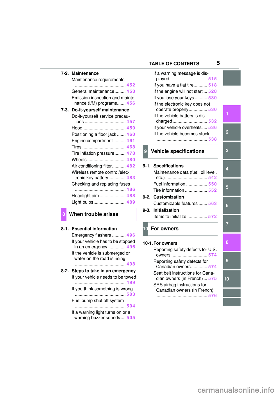
7-2. MaintenanceMaintenance requirements......................................... 452
General maintenance ......... 453
Emission inspection and mainte- nance (I/M) programs....... 456
7-3. Do-it-yourself maintenance Do-it-yourself service precau-tions ................................. 457
Hood .................................. 459
Positioning a floor jack ....... 460
Engine compartment .......... 461
Tires ................................... 468
Tire inflation pressure......... 478
Wheels ............................... 480
Air conditioning filter ........... 482
Wireless remote control/elec- tronic key battery.............. 483
Checking and replacing fuses ......................................... 486
Headlight aim ..................... 488
Light bulbs .......................... 489
8-1. Essential information Emergency flashers ........... 496
If your vehicle has to be stopped in an emergency .............. 496
If the vehicle is submerged or water on the road is rising
......................................... 498
8-2. Steps to take in an emergency If your vehicle needs to be towed......................................... 499
If you think something is wrong ......................................... 503
Fuel pump shut off system ......................................... 504
If a warning light turns on or a warning buzzer sounds .... 505If a warning message is dis-
played .............................. 515
If you have a flat tire........... 518
If the engine will not start ... 528
If you lose your keys .......... 530
If the electronic key does not operate properly............... 530
If the vehicle battery is dis- charged ............................ 532
If your vehicle overheats .... 536
If the vehicle becomes stuck ......................................... 538
9-1. Specifications Maintenance data (fuel, oil level, etc.) .................................. 542
Fuel information ................. 550
Tire information .................. 552
9-2. Customization Customizable features ....... 563
9-3. Initialization Items to initialize ................ 572
10-1. For owners Reporting safety defects for U.S.
o wners ............................. 574
Reporting safety defects for Canadian owners ............. 574
Seat belt instructions for Cana- di
an owners (in French) ... 575
SRS airbag instructions for Canadian owners (in French)......................................... 576
8When trouble arises
9Vehicle specifications
10For owners
Page 16 of 612
16Pictorial index
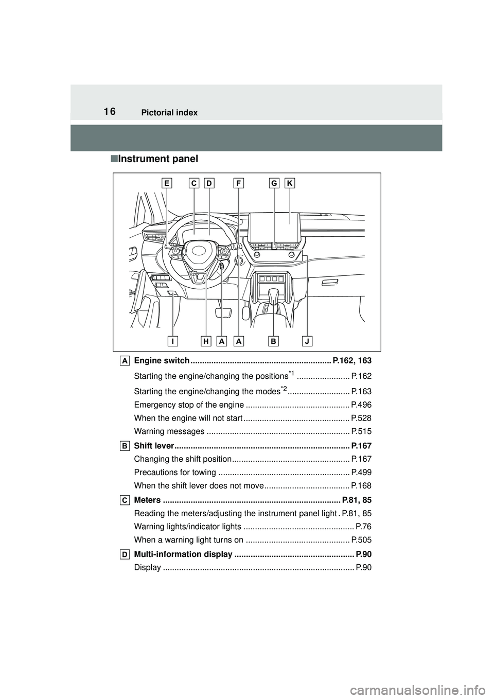
■Instrument panel
Engine switch ............................................................. P.162, 163
Starting the engine/changing the positions
*1....................... P.162
Starting the engine/changing the modes
*2........................... P.163
Emergency stop of the engine ............................................. P.496
When the engine will not start .............................................. P.528
Warning messages .............................................................. P.515
Shift lever............................................................................ P.167
Changing the shift position................................................... P.167
Precautions for towing . ........................................................ P.499
When the shift lever does not move..................................... P.168
Meters ............................................................................. P.81, 85
Reading the meters/adjusting the instrument panel light . P.81, 85
Warning lights/indicator lights ................................................ P.76
When a warning light turns on ............................................. P.505
Multi-information display ........... ......................................... P.90
Display ................................................................................... P.90
Page 19 of 612
19Pictorial index
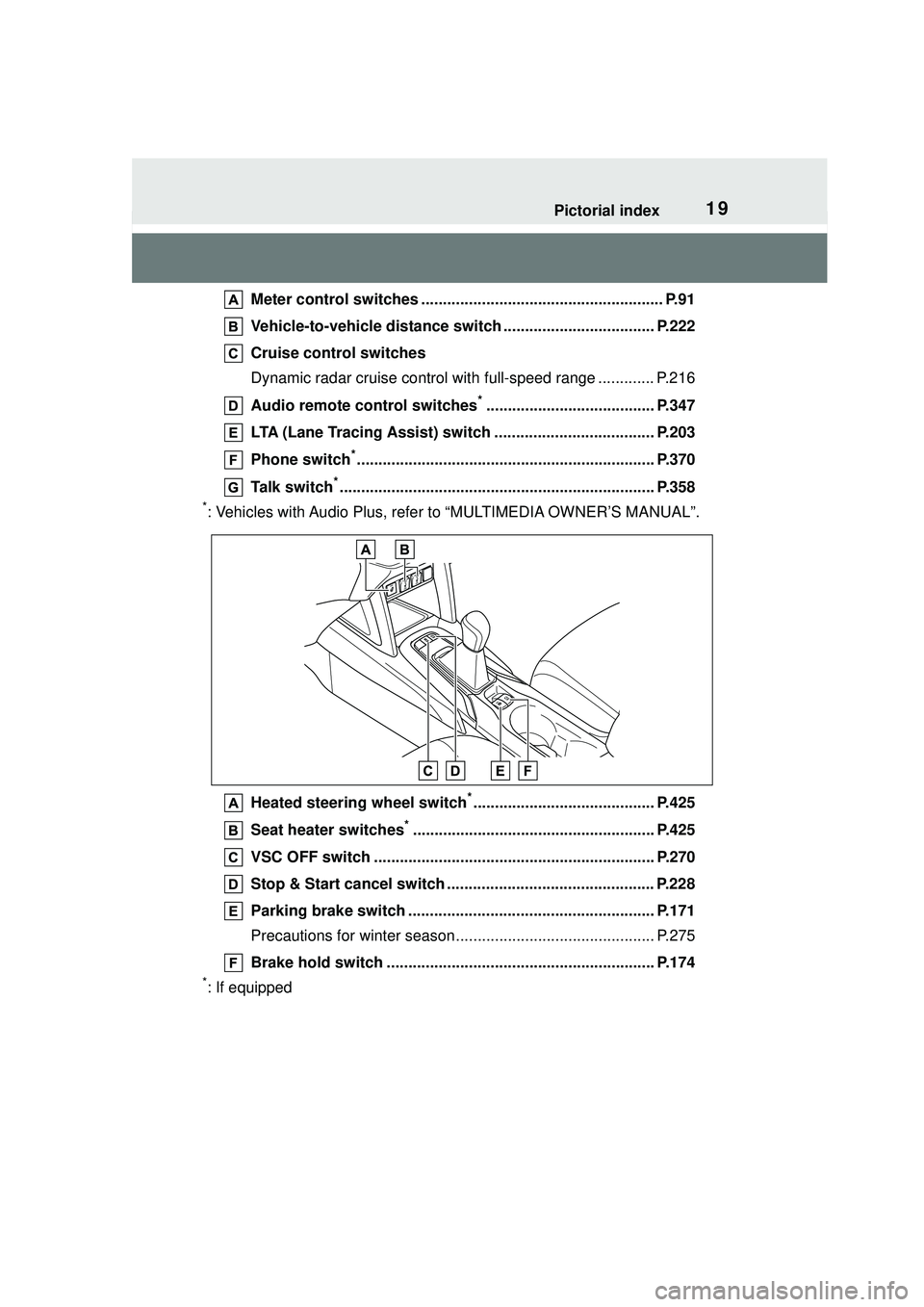
Meter control switches ........................................................ P.91
Vehicle-to-vehicle distance swit ch ................................... P.222
Cruise control switches
Dynamic radar cruise control wit h full-speed range ............. P.216
Audio remote control switches
*....................................... P.347
LTA (Lane Tracing Assist) switch ..................................... P.203
Phone switch
*..................................................................... P.370
Talk switch
*......................................................................... P.358
*: Vehicles with Audio Plus, refer to “MULTIMEDIA OWNER’S MANUAL”.
Heated steering wheel switch
*.......................................... P.425
Seat heater switches
*........................................................ P.425
VSC OFF switch ................................................................. P.270
Stop & Start cancel switch ................................................ P.228
Parking brake switch ......................................................... P.171
Precautions for winter season.... .......................................... P.275
Brake hold switch .............................................................. P.174
*: If equipped
Page 24 of 612
241-1. For safe use
1-1.For safe use
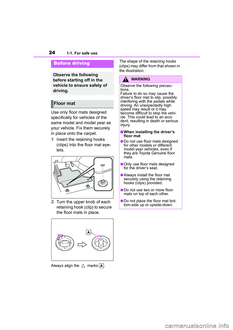
Use only floor mats designed
specifically for vehicles of the
same model and model year as
your vehicle. Fix them securely
in place onto the carpet.
1Insert the retaining hooks
(clips) into the floor mat eye-
lets.
2 Turn the upper knob of each
retaining hook (clip) to secure
the floor mats in place.
Always align the marks . The shape of the retaining hooks
(clips) may differ from that shown in
the illustration.
Before driving
Observe the following
before starting off in the
vehicle to ensure safety of
driving.
Floor mat
WARNING
Observe the following precau-
tions.
Failure to do so may cause the
driver’s floor mat to slip, possibly
interfering with the pedals while
driving. An unexpectedly high
speed may result or it may
become difficult to stop the vehi-
cle. This could lead to an acci-
dent, resulting in death or serious
injury.
■When installing the driver’s
floor mat
●Do not use floor mats designed
for other models or different
model year vehicles, even if
they are Toyota Genuine floor
mats.
●Only use floor mats designed
for the driver’s seat.
●Always install the floor mat
securely using the retaining
hooks (clips) provided.
●Do not use two or more floor
mats on top of each other.
●Do not place the floor mat bot-
tom-side up or upside-down.
Page 26 of 612
261-1. For safe use
Make sure that all occupants are
wearing their seat belts before
driving the vehicle. (P.27)
Use a child restraint system
appropriate for the child until the
child becomes large enough to
properly wear the vehicle’s seat
belt. ( P.46)
Make sure that you can see
backward clearly by adjusting
the inside and outside rear view
mirrors properly. ( P.130, 131)
WARNING
■For safe driving
Observe the following precau-
tions.
Failure to do so may result in
death or serious injury.
●Do not adjust the position of the
driver’s seat while driving.
Doing so could cause the driver
to lose control of the vehicle.
●Do not place a cushion between
the driver or passenger and the
seatback.
A cushion may prevent correct
posture from being achieved,
and reduce the effectiveness of
the seat belt and head restraint.
●Do not place anything under the
front seats.
Objects placed under the front
seats may become jammed in
the seat tracks and stop the
seat from locking in place. This
may lead to an accident and the
adjustment mechanism may
also be damaged.
●Always observe the legal speed
limit when driving on public
roads.
●When driving over long dis-
tances, take regular breaks
before you start to feel tired.
Also, if you feel tired or sleepy
while driving, do not force your-
self to continue driving and take
a break immediately.
●Take care when adjusting the
seat position to ensure that
other passengers are not
injured by the moving seat.
●When adjusting the seat posi-
tion, do not put your hands
under the seat or near the mov-
ing parts to avoid injury. Fingers
or hands may become jammed
in the seat mechanism.
Correct use of the seat
belts
Adjusting the mirrors
Page 71 of 612
711-4. Theft deterrent system
1
For safety and security
1-4.Theft deterrent system
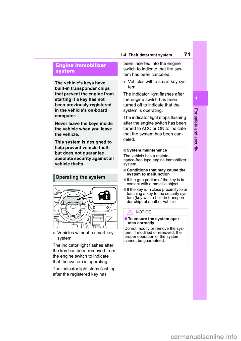
Vehicles without a smart key
system
The indicator light flashes after
the key has been removed from
the engine switch to indicate
that the system is operating.
The indicator light stops flashing
after the registered key has been inserted into the engine
switch to indicate that the sys-
tem has been canceled.
Vehicles with a smart key sys-
tem
The indicator light flashes after
the engine switch has been
turned off to indicate that the
system is operating.
The indicator light stops flashing
after the engine switch has been
turned to ACC or ON to indicate
that the system has been can-
celed.
■System maintenance
The vehicle has a mainte-
nance-free type e ngine immobilizer
system.
■Conditions that may cause the
system to malfunction
●If the grip portion of the key is in
contact with a metallic object
●If the key is in close proximity to or
touching a key to the security sys-
tem (key with a built-in transpon-
der chip) of another vehicle
Engine immobilizer
system
The vehicle’s keys have
built-in transponder chips
that prevent the engine from
starting if a key has not
been previously registered
in the vehicle’s on-board
computer.
Never leave the keys inside
the vehicle when you leave
the vehicle.
This system is designed to
help prevent vehicle theft
but does not guarantee
absolute security against all
vehicle thefts.
Operating the system
NOTICE
■To ensure the system oper-
ates correctly
Do not modify or remove the sys-
tem. If modified or removed, the
proper operation of the system
cannot be guaranteed.
Page 72 of 612
721-4. Theft deterrent system
*: If equipped
■Items to check before lock-
ing the vehicle
To prevent unexpected trigger-
ing of the alarm and vehicle
theft, make sure of the following:
Nobody is in the vehicle.
The windows and moon roof
(if equipped) are closed
before the alarm is set.
No valuables or other per-
sonal items are left in the
vehicle.
■Setting
Close the doors and hood, and
lock all the doors. The system
will set automatically after 30
seconds.
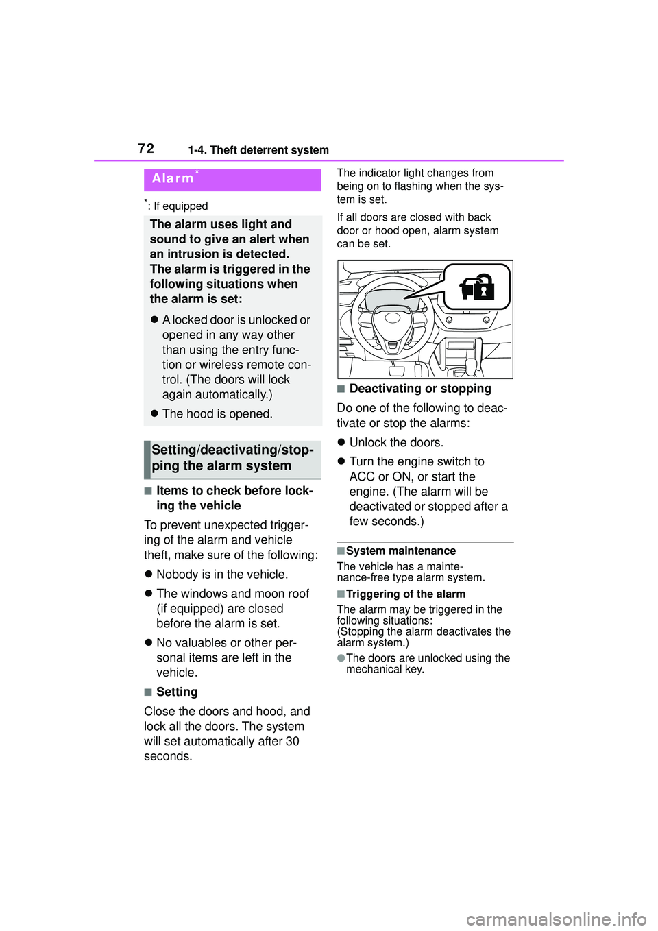
The indicator light changes from
being on to flashing when the sys-
tem is set.
If all doors are closed with back
door or hood open, alarm system
can be set.
■Deactivating or stopping
Do one of the following to deac-
tivate or stop the alarms:
Unlock the doors.
Turn the engine switch to
ACC or ON, or start the
engine. (The alarm will be
deactivated or stopped after a
few seconds.)
■System maintenance
The vehicle has a mainte-
nance-free type alarm system.
■Triggering of the alarm
The alarm may be triggered in the
following situations:
(Stopping the alarm deactivates the
alarm system.)
●The doors are unlocked using the
mechanical key.
Alarm*
The alarm uses light and
sound to give an alert when
an intrusion is detected.
The alarm is triggered in the
following situations when
the alarm is set:
A locked door is unlocked or
opened in any way other
than using the entry func-
tion or wireless remote con-
trol. (The doors will lock
again automatically.)
The hood is opened.
Setting/deactivating/stop-
ping the alarm system
Page 78 of 612
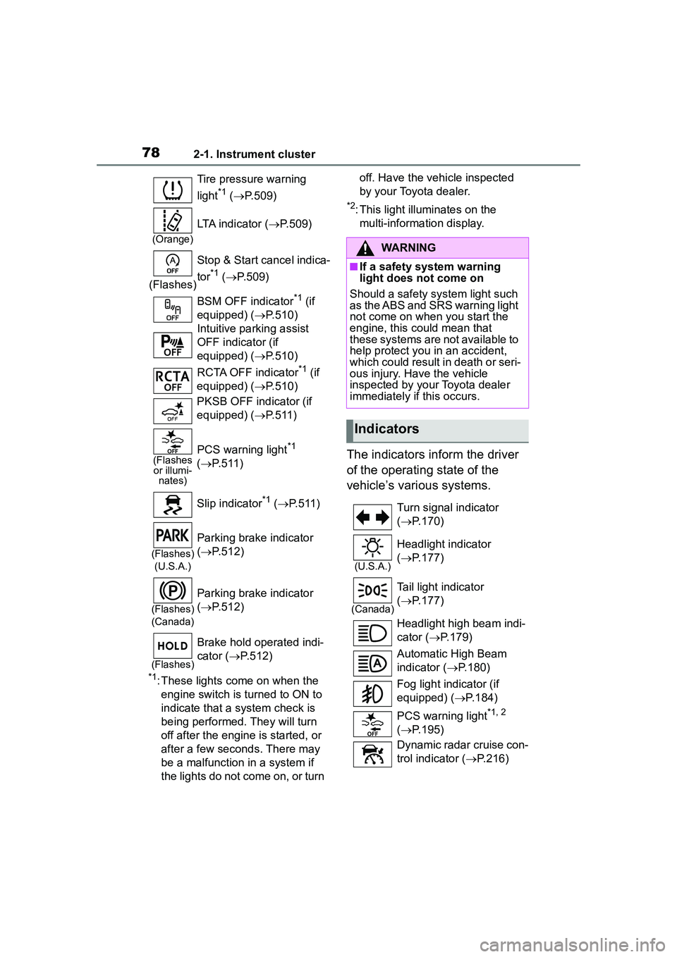
782-1. Instrument cluster
*1: These lights come on when the engine switch is turned to ON to
indicate that a system check is
being performed. They will turn
off after the engine is started, or
after a few seconds. There may
be a malfunction in a system if
the lights do not come on, or turn off. Have the vehicle inspected
by your Toyota dealer.
*2: This light illuminates on the
multi-information display.
The indicators inform the driver
of the operating state of the
vehicle’s various systems.
Tire pressure warning
light
*1 ( P.509)
(Orange)
LTA indicator ( P.509)
(Flashes) Stop & Start cancel indica-
tor
*1 (
P.509)
BSM OFF indicator
*1 (if
equipped) ( P.510)
Intuitive parking assist
OFF indicator (if
equipped) ( P.510)
RCTA OFF indicator
*1 (if
equipped) ( P.510)
PKSB OFF indicator (if
equipped) ( P.511)
(Flashes
or illumi- nates)PCS warning light*1
( P.511)
Slip indicator
*1 ( P.511)
(Flashes)
(U.S.A.)
Parking brake indicator
( P.512)
(Flashes)
(Canada)
Parking brake indicator
( P.512)
(Flashes)
Brake hold operated indi-
cator ( P.512)
WARNING
■If a safety system warning
light does not come on
Should a safety system light such
as the ABS and SRS warning light
not come on when you start the
engine, this could mean that
these systems are not available to
help protect you in an accident,
which could result in death or seri-
ous injury. Have the vehicle
inspected by your Toyota dealer
immediately if this occurs.
Indicators
Turn signal indicator
( P.170)
(U.S.A.)
Headlight indicator
( P.177)
(Canada)
Tail light indicator
( P.177)
Headlight high beam indi-
cator ( P.179)
Automatic High Beam
indicator ( P.180)
Fog light indicator (if
equipped) ( P.184)
PCS warning light
*1, 2
( P.195)
Dynamic radar cruise con-
trol indicator ( P.216)
Page 79 of 612
792-1. Instrument cluster
2
Vehicle status information and indicators
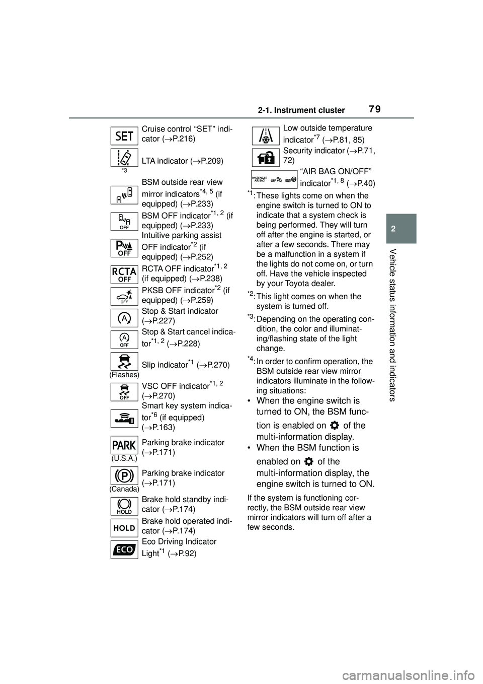
*1: These lights come on when the engine switch is turned to ON to
indicate that a system check is
being performed. They will turn
off after the engine is started, or
after a few sec onds. There may
be a malfunction in a system if
the lights do not come on, or turn
off. Have the vehicle inspected
by your Toyota dealer.
*2: This light comes on when the system is turned off.
*3: Depending on the operating con-dition, the color and illuminat-
ing/flashing state of the light
change.
*4: In order to confirm operation, the BSM outside rear view mirror
indicators illumina te in the follow-
ing situations:
• When the engine switch is
turned to ON, the BSM func-
tion is enabled on of the
multi-information display.
• When the BSM function is
enabled on of the
multi-information display, the
engine switch is turned to ON.
If the system is functioning cor-
rectly, the BSM outside rear view
mirror indicators will turn off after a
few seconds.
Cruise control “SET” indi-
cator (
P.216)
*3
LTA indicator ( P.209)
BSM outside rear view
mirror indicators
*4, 5 (if
equipped) ( P.233)
BSM OFF indicator
*1, 2 (if
equipped) ( P.233)
Intuitive parking assist
OFF indicator
*2 (if
equipped) ( P.252)
RCTA OFF indicator
*1, 2
(if equipped) ( P.238)
PKSB OFF indicator
*2 (if
equipped) ( P.259)
Stop & Start indicator
( P.227)
Stop & Start cancel indica-
tor
*1, 2 ( P.228)
(Flashes)
Slip indicator*1 ( P.270)
VSC OFF indicator
*1, 2
( P.270)
Smart key system indica-
tor
*6 (if equipped)
( P.163)
(U.S.A.)
Parking brake indicator
( P.171)
(Canada)
Parking brake indicator
( P.171)
Brake hold standby indi-
cator ( P.174)
Brake hold operated indi-
cator ( P.174)
Eco Driving Indicator
Light
*1 ( P. 9 2 )
Low outside temperature
indicator
*7 ( P.81, 85)
Security indicator ( P. 7 1 ,
72)
“AIR BAG ON/OFF”
indicator
*1, 8 ( P. 4 0 )