change time TOYOTA COROLLA CROSS 2023 Owner's Guide
[x] Cancel search | Manufacturer: TOYOTA, Model Year: 2023, Model line: COROLLA CROSS, Model: TOYOTA COROLLA CROSS 2023Pages: 500, PDF Size: 15.11 MB
Page 241 of 500
2414-5. Using the driving support systems
4
Driving
conditioning system
Press the Stop & Start cancel switch
to deactivate the Stop & Start sys-
tem.
■Changing the idling stop time
with the air conditioning system
on
The length of time the Stop & Start
system will operate when the air
conditioning system is on can be
changed in or of the
multi-informat ion display (P.82,
89). (The length of time the Stop &
Start system will op erate when the
air conditioning system is off cannot
be changed.)
■Displaying the Stop & Start sys-
tem status
P.77, 81
■Multi-information display mes-
sages
If the follo wing situations, and a
message may be displayed on the
multi-information display.
●When the engine cannot be
stopped by the Stop & Start sys-
tem
“Press Brake More to Activate”
• The brake pedal is not sufficiently depressed.
If the brake pedal is depressed
further, the system will operate.
“Non-Dedicated Battery”
• A battery not designed for use with a Stop & Start system may
have been installed.
Have the vehicl e inspected by
your Toyota dealer.
“Battery Charging”
• The battery charge may be low.
Stopping of the engine is tempo-
rarily prohibited to prioritize charging
of the battery. After the engine runs for a certain amount of time, the sys-
tem will be enabled.
• A refresh charge may be occur-
ring
After a refresh charge for up to
an hour completes, the system can
be operated.
• If displayed continuously for a long time (more than an hour)
The battery may be deteriorated.
Contact your Toyota dealer for
details.
“Stop & Start System Unavail-
able”
• The Stop & Start system is tempo- rarily disabled.
Allow the engine to run for some
time.
• The engine may have been started with the hood open.
Close the hood, turn the engine
switch off, wait f or 30 seconds or
more, and then start the engine.
“In Preparation”
• The vehicle is being driven in a high altitude area.
• The brake booster vacuum is low.
When the brake booster vacuum
reaches a predeter mined level, the
system will be enabled.
“For Climate Control”
• The air conditioning system is being used when the ambient
temperature is high or low.
If the difference between the set
temperature and cabin temperature
becomes small, the system will be
enabled.
• The windshield defogger is on.
●When the engine automatically
restarts while stopped by the Stop
Page 269 of 500
2694-5. Using the driving support systems
4
Driving
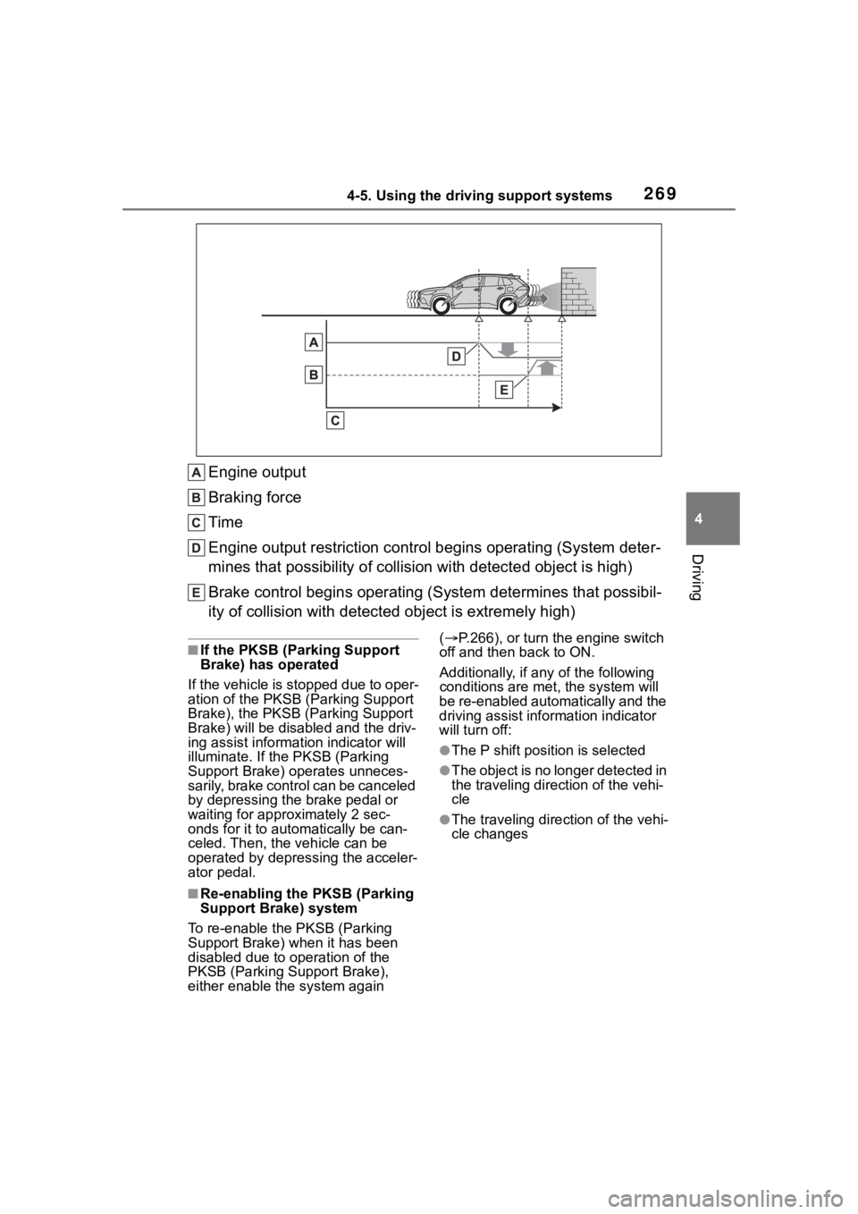
Engine output
Braking force
Time
Engine output restriction control begins operating (System deter-
mines that possibility of collision with detected object is high)
Brake control begins operating (S ystem determines that possibil-
ity of collision with detecte d object is extremely high)
■If the PKSB (Parking Support
Brake) has operated
If the vehicle is stopped due to oper-
ation of the PKSB (P arking Support
Brake), the PKSB (P arking Support
Brake) will be disabled and the driv-
ing assist informa tion indicator will
illuminate. If the PKSB (Parking
Support Brake) op erates unneces-
sarily, brake control can be canceled
by depressing the brake pedal or
waiting for approximately 2 sec-
onds for it to automatically be can-
celed. Then, the vehicle can be
operated by depress ing the acceler-
ator pedal.
■Re-enabling the PKSB (Parking
Support Brake) system
To re-enable the PKSB (Parking
Support Brake) when it has been
disabled due to operation of the
PKSB (Parking Support Brake),
either enable the system again (
P.266), or turn the engine switch
off and then back to ON.
Additionally, if a ny of the following
conditions are m et, the system will
be re-enabled automatically and the
driving assist inf ormation indicator
will turn off:
●The P shift position is selected
●The object is no longer detected in
the traveling direction of the vehi-
cle
●The traveling direction of the vehi-
cle changes
Page 287 of 500
2875-1. Using the air conditioning system and defogger
5
Interior features
■Fan speed setting
To adjust the fan speed, turn the
fan speed control switch clock-
wise (increase) or counterclock-
wise (decrease).
Pressing the on/off switch to turns
off the fan.
When the fan is o ff, pressing the
on/off switch or turning the fan
speed control switch clockwise will
turn on the fan.
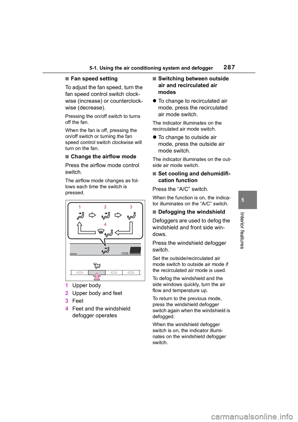
■Change the airflow mode
Press the airflow mode control
switch.
The airflow mode changes as fol-
lows each time the switch is
pressed.
1 Upper body
2 Upper body and feet
3 Feet
4 Feet and the windshield
defogger operates
■Switching between outside
air and recirculated air
modes
To change to recirculated air
mode, press the recirculated
air mode switch.
The indicator illuminates on the
recirculated air mode switch.
To change to outside air
mode, press the outside air
mode switch.
The indicator illuminates on the out-
side air mode switch.
■Set cooling and dehumidifi-
cation function
Press the “A/C” switch.
When the function is on, the indica-
tor illuminates on the “A/C” switch.
■Defogging the windshield
Defoggers are used to defog the
windshield and front side win-
dows.
Press the windshield defogger
switch.
Set the outside/recirculated air
mode switch to outside air mode if
the recirculated air mode is used.
To defog the windshield and the
side windows quickly, turn the air
flow and temperature up.
To return to the previous mode,
press the windshield defogger
switch again when the windshield is
defogged.
When the windshield defogger
switch is on, the indicator illumi-
nates on the windshield defogger
switch.
Page 294 of 500
2945-1. Using the air conditioning system and defogger
operate the right-hand side tem-
perature control switch to enter
individual mode.
Individual modes (indicator off):
The temperature for the driver’s
and front passenger’s side can be
adjusted separately.
■Setting the fan speed
Vehicles without DUAL mode
air conditioning system
To adjust the fan speed, turn the
fan speed control switch clock-
wise (increase) or counterclock-
wise (decrease).
Pressing the off switch to turns off
the fan.
Vehicles with DUAL mode air
conditioning system
Operate the fan speed
increases switch to increase the
fan speed and the fan speed
decrease switch to decrease the
fan speed.
Pressing the off switch to turns off
the fan.
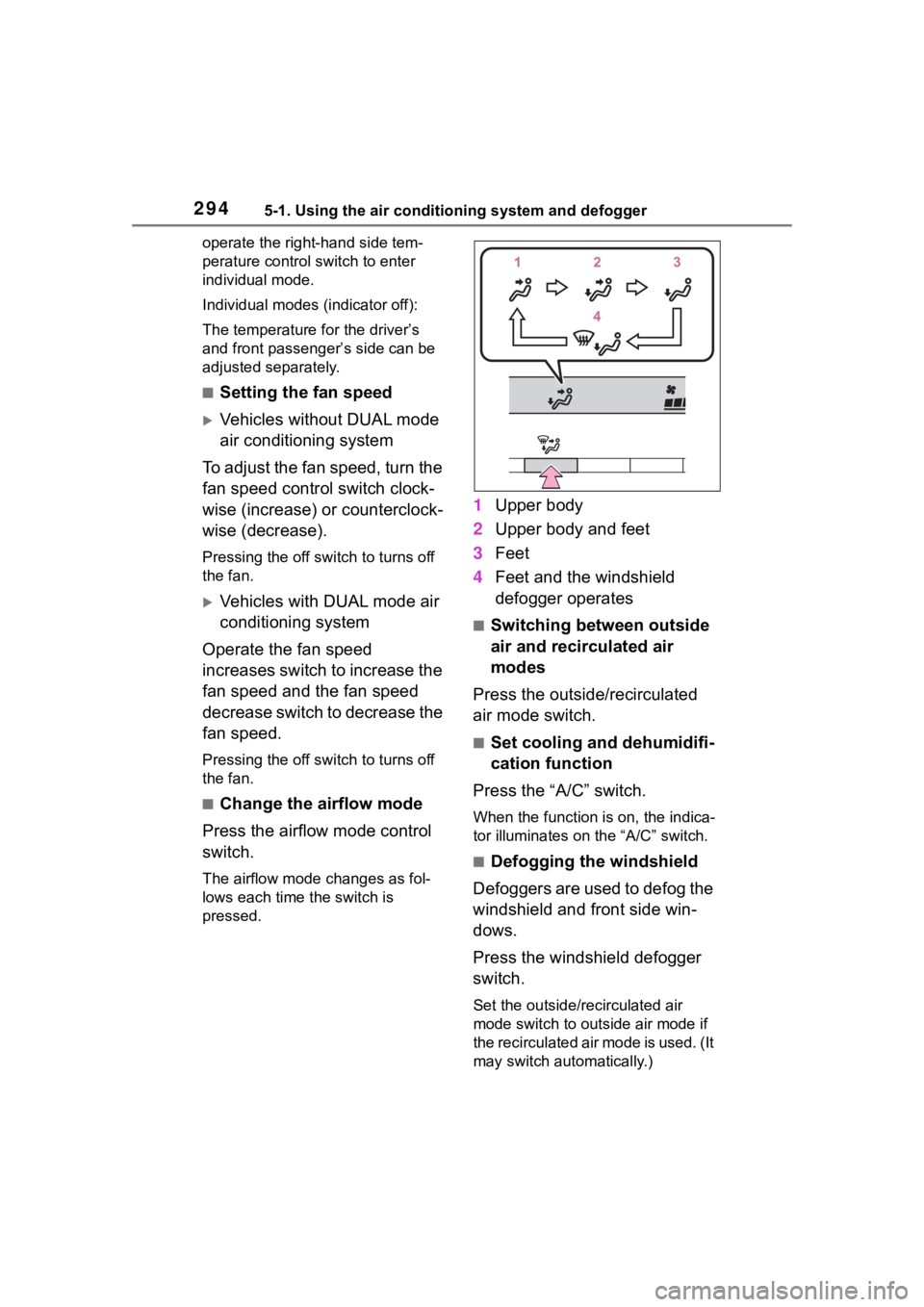
■Change the airflow mode
Press the airflow mode control
switch.
The airflow mode changes as fol-
lows each time the switch is
pressed.
1 Upper body
2 Upper body and feet
3 Feet
4 Feet and the windshield
defogger operates
■Switching between outside
air and recirculated air
modes
Press the outside/recirculated
air mode switch.
■Set cooling and dehumidifi-
cation function
Press the “A/C” switch.
When the function is on, the indica-
tor illuminates on the “A/C” switch.
■Defogging the windshield
Defoggers are used to defog the
windshield and front side win-
dows.
Press the windshield defogger
switch.
Set the outside/recirculated air
mode switch to outside air mode if
the recirculated air mode is used. (It
may switch automatically.)
Page 298 of 500
2985-1. Using the air conditioning system and defogger
Indicator illuminated: Airflow
to the front seats only
Indicator off: Airflow to all the
seats
■Operation of automatic airflow
control
●In order to maintain a comfortable
interior, airflow may be directed to
seats without passengers immedi-
ately after the e ngine is started
and at other times depending on
the outside temperature.
●After the engine is started, if pas-
sengers move around inside or
enter/exit the vehicle, the system
cannot accurately detect the pres-
ence of passengers and automatic
airflow control will not operate.
■Operation of manual airflow
control
Even if the function is manually
switched to directing airflow to only
the front seats, whe n a rear seat is
occupied, it may automatically direct
airflow to all seats.
■To return to automatic airflow
control
1 With the indicator off, turn the
engine switch off.
2 After 60 minutes or more elapse,
turn the engine switch to ON.
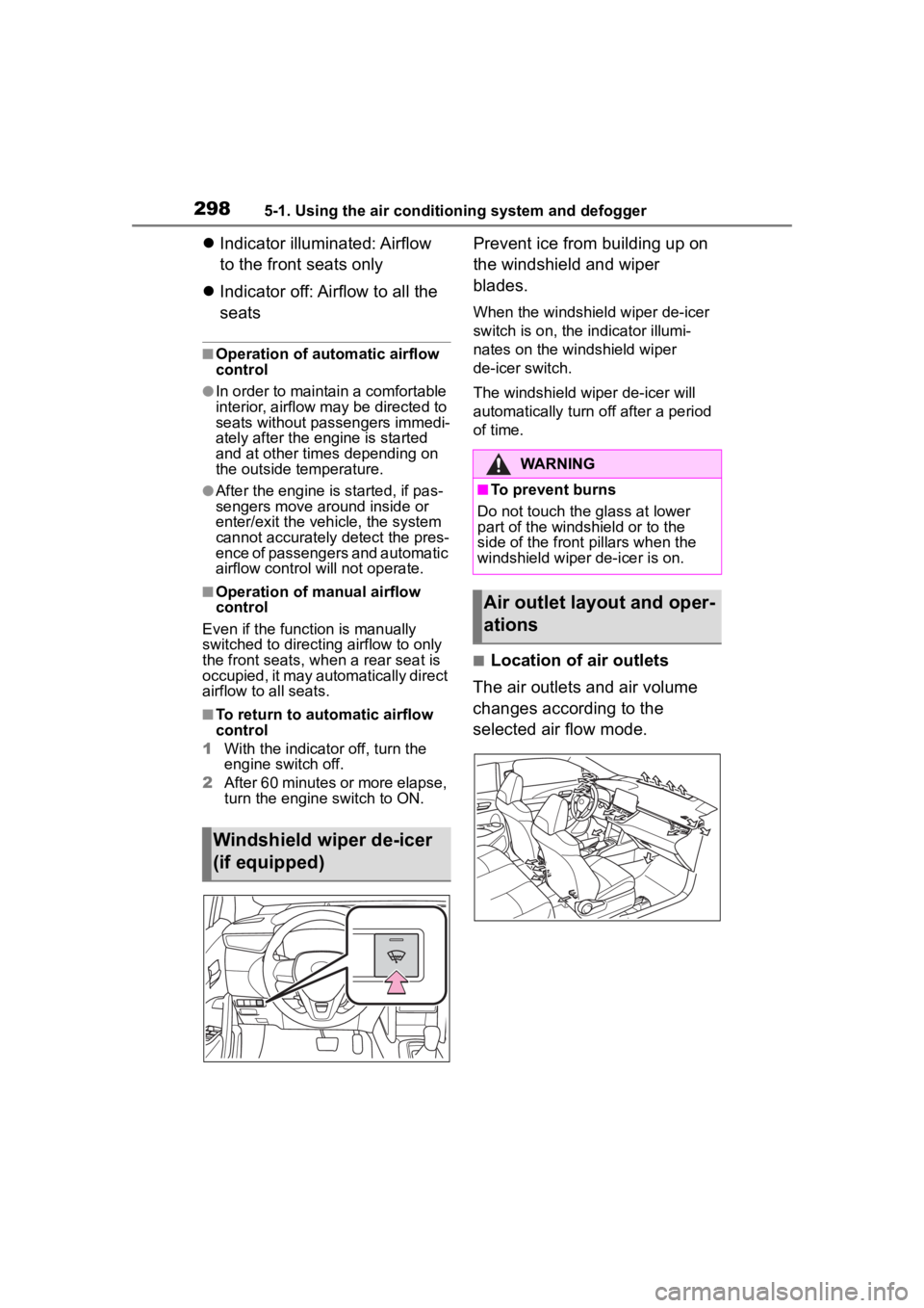
Prevent ice from building up on
the windshield and wiper
blades.
When the windshield wiper de-icer
switch is on, the indicator illumi-
nates on the windshield wiper
de-icer switch.
The windshield wiper de-icer will
automatically turn off after a period
of time.
■Location of air outlets
The air outlets and air volume
changes according to the
selected air flow mode.
Windshield wiper de-icer
(if equipped)
WARNING
■To prevent burns
Do not touch the glass at lower
part of the windshield or to the
side of the front p illars when the
windshield wiper de-icer is on.
Air outlet layout and oper-
ations
Page 313 of 500
3135-4. Other interior features
5
Interior features
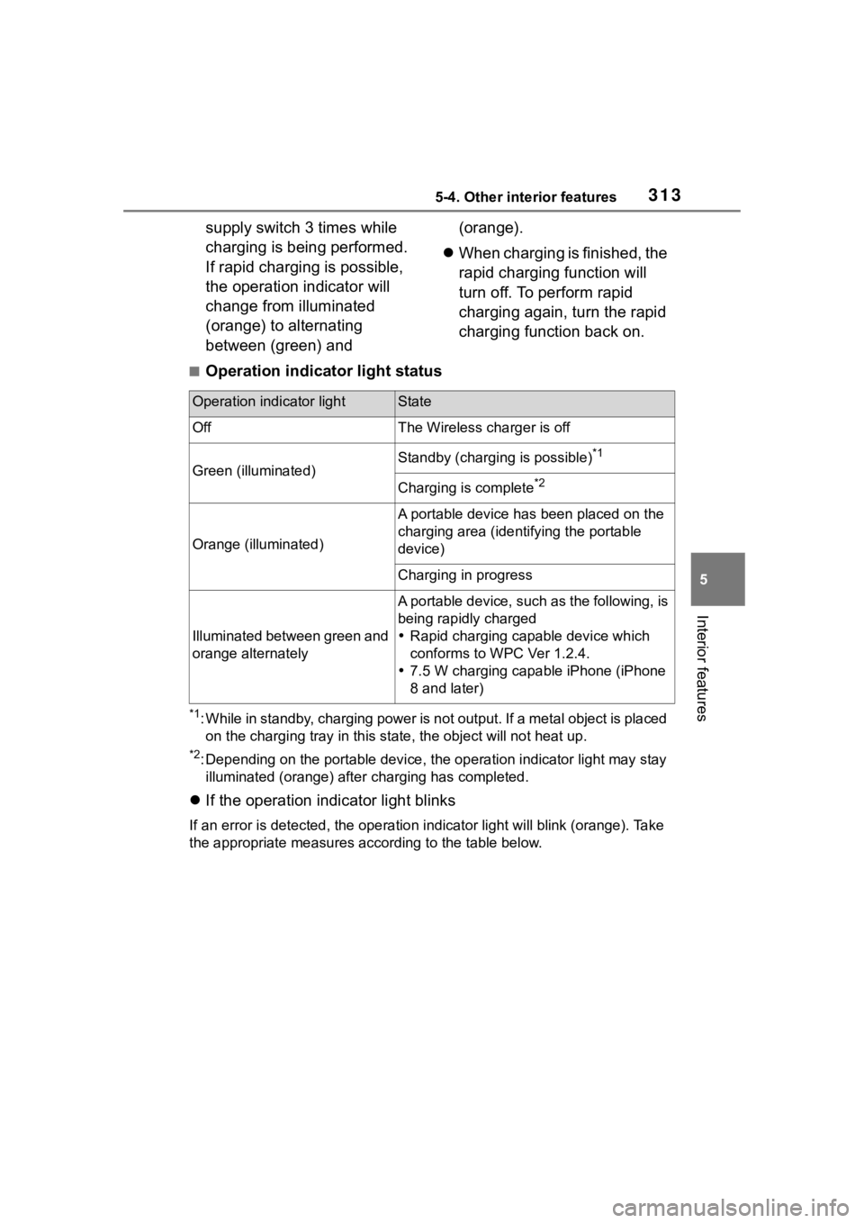
supply switch 3 times while
charging is being performed.
If rapid charging is possible,
the operation indicator will
change from illuminated
(orange) to alternating
between (green) and (orange).
When charging is finished, the
rapid charging function will
turn off. To perform rapid
charging again, turn the rapid
charging function back on.
■Operation indicator light status
*1: While in standby, charging power is not output. If a metal obj ect is placed
on the charging tray i n this state, the object will not heat up .
*2: Depending on the portable device, the operation indicator light may stay
illuminated (orang e) after charging has completed.
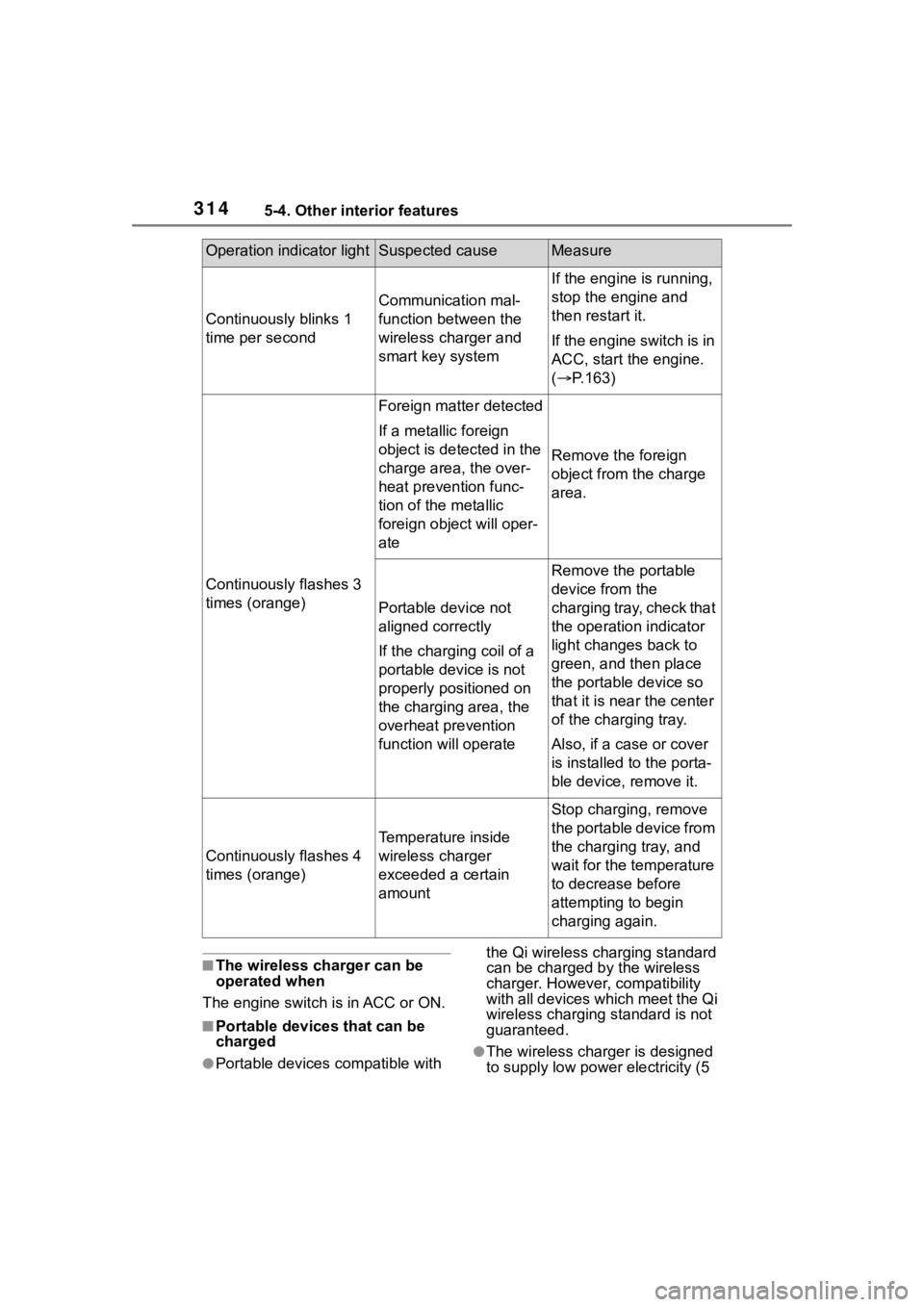
If the operation indicator light blinks
If an error is detec ted, the operation in dicator light will blink (orange). Take
the appropriate measures according to the table below.
Operation indicator lightState
OffThe Wireless charger is off
Green (illuminated)Standby (charging is possible)*1
Charging is complete*2
Orange (illuminated)
A portable device has been placed on the
charging area (identifying the portable
device)
Charging in progress
Illuminated between green and
orange alternately
A portable device, such as the following, is
being rapidly charged
Rapid charging capable device which
conforms to WPC Ver 1.2.4.
7.5 W charging capable iPhone (iPhone
8 and later)
Page 314 of 500
3145-4. Other interior features
■The wireless charger can be
operated when
The engine switch is in ACC or ON.
■Portable devices that can be
charged
●Portable devices compatible with the Qi wireless charging standard
can be charged by the wireless
charger. However, compatibility
with all devices which meet the Qi
wireless charging standard is not
guaranteed.●The wireless char
ger is designed
to supply low power electricity (5
Operation indicator lightSuspected causeMeasure
Continuously blinks 1
time per second
Communication mal-
function between the
wireless charger and
smart key system
If the engine is running,
stop the engine and
then restart it.
If the engine switch is in
ACC, start the engine.
( P.163)
Continuously flashes 3
times (orange)
Foreign matter detected
If a metallic foreign
object is detected in the
charge area, the over-
heat prevention func-
tion of the metallic
foreign obje ct will oper-
ate
Remove the foreign
object from the charge
area.
Portable device not
aligned correctly
If the charging coil of a
portable device is not
properly positioned on
the charging area, the
overheat prevention
function will operate
Remove the portable
device from the
charging tray, check that
the operation indicator
light changes back to
green, and then place
the portable device so
that it is near the center
of the charging tray.
Also, if a case or cover
is installed to the porta-
ble device, remove it.
Continuously flashes 4
times (orange)
Temperature inside
wireless charger
exceeded a certain
amount
Stop charging, remove
the portable device from
the charging tray, and
wait for the temperature
to decrease before
attempting to begin
charging again.
Page 315 of 500
3155-4. Other interior features
5
Interior features
W or less) to a cellular phone,
smartphone, or other portable
device.
●However, portable devices, such
as the following, can be charged
with more than 5 W.
• 7.5 W charging compatible iPhones can be ch arged at 7.5 W
or less.
• Portable devices compliant with EPP output as defined by WPC
standard Ver1.2.4. can be
charged at 10 W or less.
■Using the smart key system
During charging, when the smart
key system searches for an elec-
tronic key, charging may be tempo-
rarily suspended.
■If a cover or accessory is
attached to the portable device
Do not charge a portable device if a
cover or accessory which is not Qi
compatible is attached. Depending
on the type of cover (including the
certain genuine manufacture parts)
and/or accessory attached, it may
not be possible to charge the porta-
ble device. If the portable device is
placed on the charging area and
does not charge, remove the cover
and/or accessories.
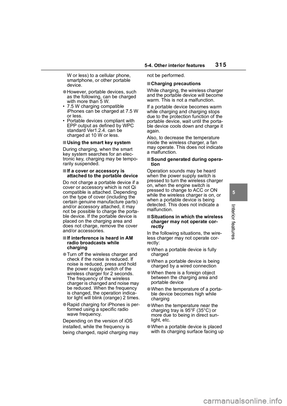
■If interference is heard in AM
radio broadcasts while
charging
●Turn off the wireless charger and
check if the noise is reduced. If
noise is reduced, press and hold
the power supply switch of the
wireless charger for 2 seconds.
The frequency of the wireless
charger is changed and noise may
be reduced. When the frequency
is changed, the operation indica-
tor light will blink (orange) 2 times.
●Rapid charging for iPhones is per-
formed using a specific radio
wave frequency.
Depending on the version of iOS
installed, while th e frequency is
being changed, rapid charging may not be performed.
■Charging precautions
While charging, the wireless charger
and the portable device will become
warm. This is not a malfunction.
If a portable device becomes warm
while charging and charging stops
due to the protection function of the
portable device, wai t until the porta-
ble device cools down and charge it
again.
Also, to decrease the temperature
inside the wireless charger, a fan
may operate. This does not indicate
a malfunction.
■Sound generated during opera-
tion
Operation sounds may be heard
when the power supply switch is
pressed to turn the wireless charger
on, when the engine switch is
pressed to change to ACC or ON
while the wireless charger is on, or
when a portable device is being
detected. This does not indicate a
malfunction.
■Situations in which the wireless
charger may not operate cor-
rectly
In the following situ ations, the wire-
less charger may not operate cor-
rectly:
●When a portable device is fully
charged
●When a portable device is being
charged by a wired connection
●When there is a foreign object
between the charging area and
portable device
●When the temperature of a porta-
ble device becomes high while
charging
●When the temperature near the
charging tray is 95°F (35°C) or
more due to being in direct sun-
light, etc.
●When a portable device is placed
with its charging surface facing up
Page 355 of 500
3556-3. Do-it-yourself maintenance
6
Maintenance and care
pressure warning system may not
operate properly.
• If non-genuine Toyota wheels are
used.
• A tire has been replaced with a tire that is not an OE (Original
Equipment) tire.
• A tire has been replaced with a tire that is not of the specified size.
• Tire chains, etc. are equipped.
• An auxiliary-supported run-flat tire is equipped.
• If a window tint that affects the radio wave signals is installed.
• If there is a lot of snow or ice on
the vehicle, particularly around the
wheels or wheel housings.
• If the tire inflation pressure is
extremely higher than the speci-
fied level.
• If wheel without tire pressure
warning valves a nd transmitters
are used.
• If the ID code on the tire pressure
warning valves and transmitters is
not registered in the tire pressure
warning computer.
●Performance may be affected in
the following situations.
• Near a TV tower, electric power plant, gas station, radio station,
large display, airpo rt or other facil-
ity that generates strong radio
waves or electrical noise
• When carrying a portable radio,
cellular phone, cordless phone or
other wireless communication
device
●If tire position information is not
correctly displayed due to the
radio wave conditions, the display
may be corrected by driving and
changing the radio wave condi-
tions.
●When the vehicle is parked, the
time taken for the warning to start
or go off could be extended.
●When tire inflation pressure
declines rapidly for example when
a tire has burst, the warning may
not function.
■Warning performance of the tire
pressure warning system
The warning of the tire pressure
warning system w ill change in
accordance with the conditions
under which it was initialized. For
this reason, the system may give a
warning even if th e tire pressure
does not reach a low enough level,
or if the pressure is higher than the
pressure that was adjusted to when
the system was initialized.
When replacing tires or wheels,
tire pressure warning valves and
transmitters must also be
installed.
When new tire pressure warning
valves and transmitters are
installed, new ID codes must be
registered in the tire pressure
warning computer and the tire
pressure warning system must
be initialized. ( P.358)
■When replacing the tires and
wheels
If the ID code of the tire pressure
warning valve and tr ansmitter is not
registered, the tire pressure warning
system will not work properly. After
driving for about 20 minutes, the tire
pressure warning light blinks for 1
minute and stays on to indicate a
system malfunction.
Installing tire pressure
warning valves and trans-
mitters
Page 361 of 500
3616-3. Do-it-yourself maintenance
6
Maintenance and care
erly. Perform the ID code registra-
tion procedure again.
• If, when attempting to start ID
code registration, the tire pressure
warning light does not blink slowly
3 times.
• If, when the vehicle has been driven for about 20 minutes after
performing ID co de registration,
the tire pressur e warning light
blinks for approxi mately 1 minute
and then illu minates.
If the ID codes cannot be registered
even when performing the above
procedure, contact your Toyota
dealer.
Your vehicle is equipped with
tire pressure warning system
with the function to have ID
codes registered for a second
wheel set, for example a winter
set. You can register a second
wheel set by yourself or your
Toyota dealer.
After registration of a second
wheel set, either of these two
wheel sets can be selected for
usage with the tire pressure
warning system.
■Operating conditions for
the function
This function will perform the
change of wheel set only if a
second wheel set has been
registered. If no second wheel
set has been registered, no
change will be made when
selecting this function in the
menu.
Only a change between both registered wheel set is possi-
ble, mixing between these
wheel sets is not supported.
■How to change between
wheel sets
1 Have the vehicle fitted with
the preferred wheel set.
2 4.2-inch display meter:
Press or of the meter
control switch to select .
7-inch display meter:
Press or of the meter
control switch to select .
3 4.2-inch display meter:
Press or to select
“Vehicle Settings” and then
press and hold .
7-inch display meter:
Press or to select “Vehi-
cle Settings” and then press and
hold .
4 4.2-inch display meter:
Press or to select
“TPWS setting” and then
press .
7-inch display meter:
Press or to select
“TPWS setting” and then press .
5 4.2-inch display meter:
Press or to select
Selecting wheel set