check engine TOYOTA COROLLA HATCHBACK 2023 Owner's Manual
[x] Cancel search | Manufacturer: TOYOTA, Model Year: 2023, Model line: COROLLA HATCHBACK, Model: TOYOTA COROLLA HATCHBACK 2023Pages: 436, PDF Size: 8.72 MB
Page 136 of 436
1364-2. Driving procedures
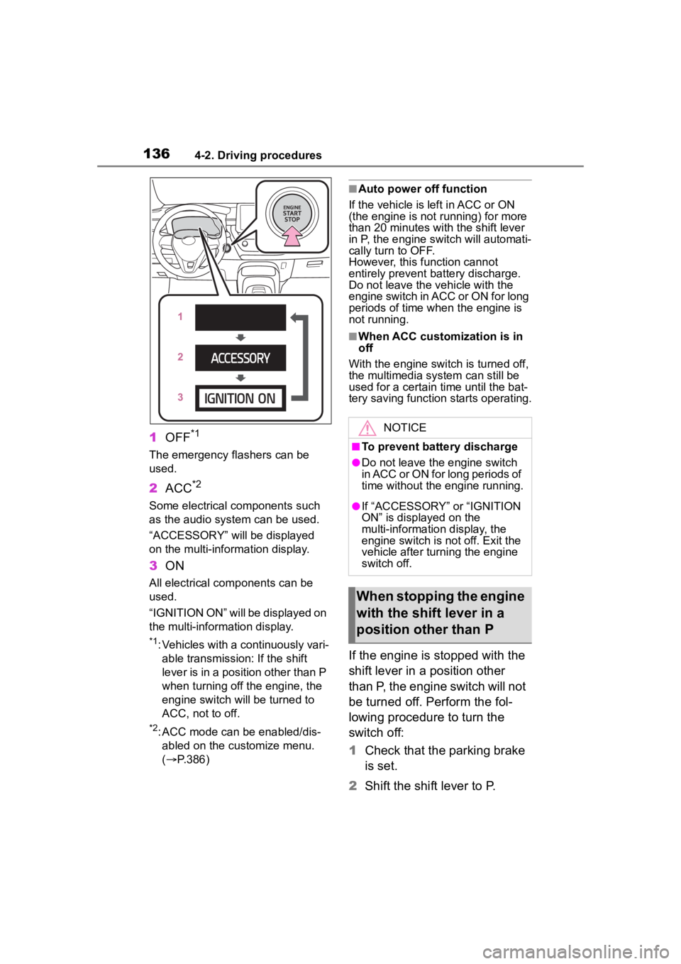
1OFF*1
The emergency flashers can be
used.
2ACC*2
Some electrical components such
as the audio system can be used.
“ACCESSORY” will be displayed
on the multi-information display.
3ON
All electrical com ponents can be
used.
“IGNITION ON” will be displayed on
the multi-information display.
*1: Vehicles with a continuously vari- able transmission: If the shift
lever is in a position other than P
when turning off the engine, the
engine switch will be turned to
ACC, not to off.
*2: ACC mode can be enabled/dis-abled on the customize menu.
( P.386)
■Auto power off function
If the vehicle is left in ACC or ON
(the engine is not running) for more
than 20 minutes with the shift lever
in P, the engine switch will automati-
cally turn to OFF.
However, this function cannot
entirely prevent b attery discharge.
Do not leave the v ehicle with the
engine switch in ACC or ON for long
periods of time when the engine is
not running.
■When ACC customization is in
off
With the engine switch is turned off,
the multimedia system can still be
used for a certain time until the bat-
tery saving function starts operating.
If the engine is stopped with the
shift lever in a position other
than P, the engine switch will not
be turned off. Perform the fol-
lowing procedure to turn the
switch off:
1 Check that the parking brake
is set.
2 Shift the shift lever to P.
NOTICE
■To prevent battery discharge
●Do not leave the engine switch
in ACC or ON for long periods of
time without the engine running.
●If “ACCESSORY” or “IGNITION
ON” is displayed on the
multi-information display, the
engine switch is not off. Exit the
vehicle after turning the engine
switch off.
When stopping the engine
with the shift lever in a
position other than P
Page 137 of 436

1374-2. Driving procedures
4
Driving
3Check that “IGNITION ON” is
displayed on the multi-infor-
mation display and press the
engine switch shortly and
firmly.
4 Check that “ACCESSORY”
or “IGNITION ON” on the
multi-information display are
off.
*: To improve fuel efficiency and
reduce noise, shift the shift lever
to D for normal driving.
■To protect the continuously
variable transmission
If the continuously variable trans-
mission fluid temperature is high,
“Transmission Oil Temp. High Stop
in a safe place and See owner’s
manual” will be displayed on the
multi-information display and the
vehicle will go into transmission pro-
tection mode automatically. Have
the vehicle inspected by your Toyota
dealer.
NOTICE
■To prevent battery discharge
Do not stop the engine when the
shift lever is in a position other
than P. If the engin e is stopped in
another shift lever position, the
engine switch will not be turned
off and remained to ON. If the
vehicle is left in ON, battery dis-
charge may occur.
Continuously variable
transmission
Select the shift position
depending on your purpose
and situation.
Shift position purpose
and functions
Shift posi-
tionObjective or function
PParking the vehi-
cle/starting the engine
RReversing
N
Neutral
(Condition in which the power is not transmit- ted)
DNormal driving*
M
10-speed sport sequen-tial shiftmatic mode driving ( P.140)
Page 139 of 436
1394-2. Driving procedures
4
Driving
■Shift lock system
The shift lock system is a system to
prevent accidental operation of the
shift lever in starting.
The shift lever can be shifted from P
only when the engine switch is in
ON and the brake pedal is being
depressed.
■If the shift lever cannot be
shifted from P
First, check whether the brake pedal
is being depressed.
If the shift lever cannot be shifted
with your foot on the brake pedal,
there may be a pr oblem with the
shift lock system. Have the vehicle
inspected by your Toyota dealer
immediately.
The following steps may be used as
an emergency measure to ensure
that the shift lev er can be shifted.
Releasing the shift lock:
1 Set the parking brake.
2 Turn the engine switch off.
3 Depress the brake pedal.
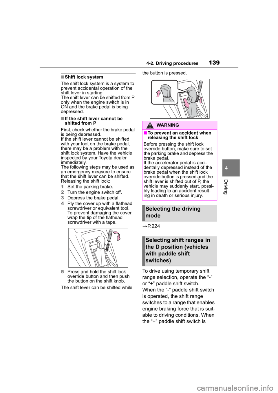
4 Ply the cover up with a flathead
screwdriver or equivalent tool.
To prevent damaging the cover,
wrap the tip of the flathead
screwdriver with a tape.
5 Press and hold the shift lock
override button and then push
the button on the shift knob.
The shift lever can be shifted while the button is pressed.
P.224
To drive using temporary shift
range selection, operate the “-”
or “+” paddle shift switch.
When the “-” paddl e shift switch
is operated, the shift range
switches to a range that enables
engine braking force that is suit-
able to driving conditions. When
the “+” paddle shift switch is
WARNING
■To prevent an accident when
releasing the shift lock
Before pressing the shift lock
override button, m ake sure to set
the parking brake and depress the
brake pedal.
If the accelerator pedal is acci-
dentally depressed instead of the
brake pedal when the shift lock
override button is pressed and the
shift lever is shifted out of P, the
vehicle may suddenly start, possi-
bly leading to an accident result-
ing in death or serious injury.
Selecting the driving
mode
Selecting shift ranges in
the D position (vehicles
with paddle shift
switches)
Page 141 of 436
1414-2. Driving procedures
4
Driving
However, even when in the M
position, the gear steps will be
automatically changed if the
engine speed is too high, or too
low.
■Gear step functions
●You can choose from 10 levels of
engine braking force.
●A lower gear step will provide
greater engine braking force than
a higher gear step, and the engine
speed will also increase.
■When the vehic le comes to a
stop with the shift lever in the M
position
●The transmission will automati-
cally downshift to M1 once the
vehicle is stopped.
●After a stop, the vehicle will start
off in M1.
●When the vehicle is stopped, the
transmission is set at M1.
■Downshifting restriction warn-
ing buzzer
To help ensure safety and driving
performance, downshifting opera-
tion may sometimes b e restricted. In
some circumstances, downshifting
may not be possible even when the
shift lever or paddle shift switch (if
equipped) is operated. (A buzzer
will sound twice.)
■If the 10-speed sport sequential
shiftmatic mode indicator does
not come on even after shifting
the shift lever to M
This may indicate a malfunction in
the continuously variable transmis-
sion system. Have the vehicle
inspected by your Toyota dealer
immediately.
(In this situation, the transmission
will operate in t he same manner as
when the shift lever is in D.)
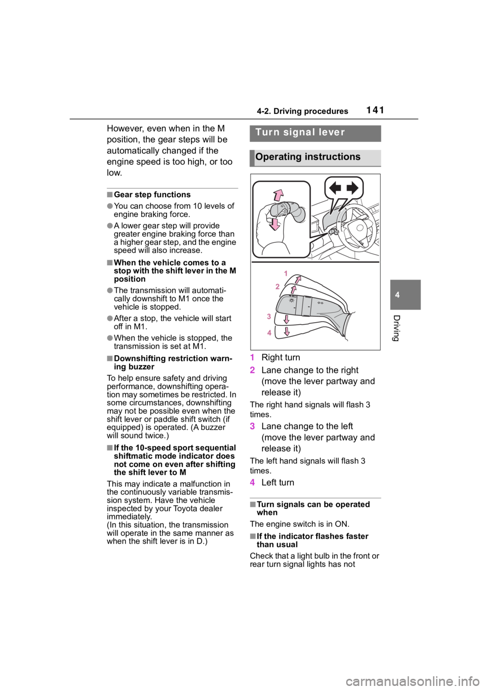
1 Right turn
2 Lane change to the right
(move the lever partway and
release it)
The right hand s ignals will flash 3
times.
3 Lane change to the left
(move the lever partway and
release it)
The left hand signals will flash 3
times.
4Left turn
■Turn signals can be operated
when
The engine switch is in ON.
■If the indicator flashes faster
than usual
Check that a light bulb in the front or
rear turn signal lights has not
Tur n signal lever
Operating instructions
Page 155 of 436

1554-3. Operating the lights and wipers
4
Driving
■The windshield wiper and
washer can be operated when
The engine switch is in ON.
■If no windshield washer fluid
sprays
Check that the wash er nozzles are
not blocked if there is washer fluid in
the windshield washer fluid reser-
v oi r.
■When stopping the engine in an
emergency while driving
If the windshield wipers are operat-
ing when the engine is stopped, the
windshield wipers will operate in
high speed operation. After the vehi-
cle is stopped, operation will return
to normal when the engine switch is
turned to ON, or op eration will stop
when the driver’s door is opened.
Operating the switch
operates the rear wiper as fol-
lows:
1 (U.S.A.) or (Canada)
Intermittent window wiper
operation
2 (U.S.A.) or (Canada)
Normal window wiper opera-
tion
WARNING
■Caution regarding the use of
washer fluid
When it is cold, do not use the
washer fluid until the windshield
becomes warm. The fluid may
freeze on the windshield and
cause low visibility. This may lead
to an accident, resulting in death
or serious injury.
NOTICE
■When the washer fluid tank is
empty
Do not operate the switch continu-
ally as the washer fluid pump may
overheat.
■When a nozzle becomes
blocked
In this case, contact your Toyota
dealer. Do not try to clear it with a
pin or other object. The nozzle will
be damaged.
Rear window wiper
and washer
Operating the lever can use
the rear window wiper or the
washer.
NOTICE
■When the rear window is dry
Do not use the wiper, as it may
damage the rear window.
Operating instructions
Page 156 of 436
1564-3. Operating the lights and wipers
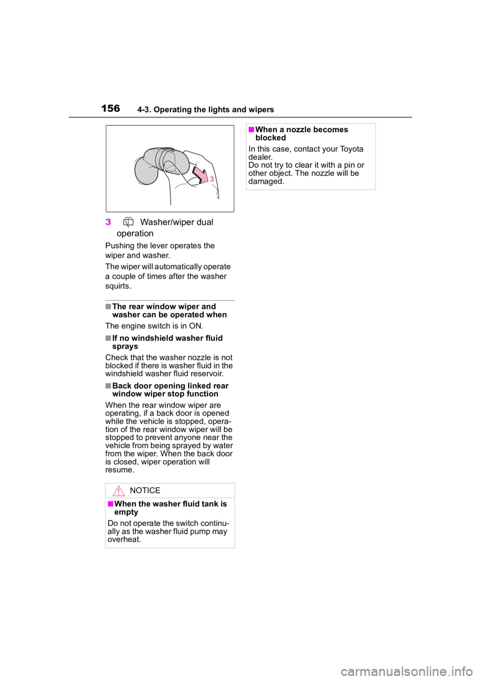
3Washer/wiper dual
operation
Pushing the lever operates the
wiper and washer.
The wiper will automatically operate
a couple of times after the washer
squirts.
■The rear window wiper and
washer can be operated when
The engine switch is in ON.
■If no windshield washer fluid
sprays
Check that the washer nozzle is not
blocked if there is washer fluid in the
windshield washer fluid reservoir.
■Back door opening linked rear
window wiper stop function
When the rear wi ndow wiper are
operating, if a back door is opened
while the vehicle is stopped, opera-
tion of the rear window wiper will be
stopped to prevent anyone near the
vehicle from being sprayed by water
from the wiper. When the back door
is closed, wiper operation will
resume.
NOTICE
■When the washer fluid tank is
empty
Do not operate the switch continu-
ally as the washer fluid pump may
overheat.
■When a nozzle becomes
blocked
In this case, contact your Toyota
dealer.
Do not try to clear it with a pin or
other object. The nozzle will be
damaged.
Page 254 of 436
2545-4. Other interior features
■The wireless charger can be
operated when
The engine switch is in ACC or ON.
■Portable devices that can be
charged
●Portable devices compatible with
the Qi wireless charging standard
can be charged by the wireless
charger. However, compatibility
with all devices which meet the Qi
wireless charging standard is not
guaranteed.
●The wireless charger is designed
to supply low power electricity (5
W or less) to a cellular phone,
smartphone, or other portable
device.
■If a cover or accessory is
attached to the portable device
Do not charge a portable device if a
cover or accessory which is not Qi
compatible is attached. Depending
on the type of cover (including for
certain genuine manufacture parts)
and/or accessory attached, it may
not be possible to charge the porta-
ble device. If the portable device is
placed on the charging area and
does not charge, remove the cover and/or accessories.
■If interference is heard in AM
radio broadcasts while
charging
Turn off the wireless charger and
check if the noise is reduced. If
noise is reduced, press and hold the
power supply switch of the wireless
charger for 2 se conds. The fre-
quency of the wireless charger is
changed and noise may be
reduced. When the frequency is
changed, the operation indicator
light will blink (orange) 2 times.
■Charging precautions
●If the electronic key cannot be
detected in the cabin, charging
cannot be performed. When a
door is opened and closed,
charging may be temporarily sus-
pended.
●While charging, the wireless char-
ger and the portable device will
become warm.
This is not a malfunction.If a porta-
ble device becomes warm while
charging and charging stops due
to the protection f unction of the
portable device, wait until the por-
table device cools down and
charge it again.
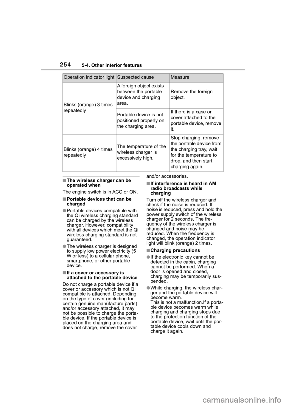
Blinks (orange) 3 times
repeatedly
A foreign object exists
between the portable
device and charging
area.
Remove the foreign
object.
Portable device is not
positioned properly on
the charging area.If there is a case or
cover attached to the
portable device, remove
it.
Blinks (orange) 4 times
repeatedlyThe temperature of the
wireless charger is
excessively high.
Stop charging, remove
the portable device from
the charging tray, wait
for the temperature to
drop, and then start
charging again.
Operation indicator lightSuspected causeMeasure
Page 257 of 436
2575-4. Other interior features
5
Interior features
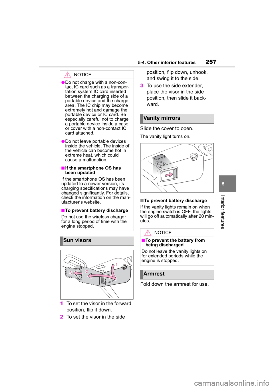
1To set the visor in the forward
position, flip it down.
2 To set the visor in the side position, flip down, unhook,
and swing it to the side.
3 To use the side extender,
place the visor in the side
position, then slide it back-
ward.
Slide the cover to open.
The vanity lig ht turns on.
■To prevent bat tery discharge
If the vanity lights remain on when
the engine switch is OFF, the lights
will go off automatically after 20 min-
utes.
Fold down the armrest for use.
NOTICE
●Do not charge with a non-con-
tact IC card such as a transpor-
tation system IC card inserted
between the charging side of a
portable device and the charge
area. The IC chip may become
extremely hot and damage the
portable device or IC card. Be
especially careful not to charge
a portable device inside a case
or cover with a non-contact IC
card attached.
●Do not leave portable devices
inside the vehicle. The inside of
the vehicle can become hot in
extreme heat, which could
cause a malfunction.
■If the smartphone OS has
been updated
If the smartphone OS has been
updated to a new er version, its
charging specifications may have
changed significantly. For details,
check the information on the man-
ufacturer’s website.
■To prevent battery discharge
Do not use the wireless charger
for a long period of time with the
engine stopped.
Sun visors
Vanity mirrors
NOTICE
■To prevent the battery from
being discharged
Do not leave the vanity lights on
for extended periods while the
engine is stopped.
Armrest
Page 259 of 436
259
6
6
Maintenance and care
Maintenance and care
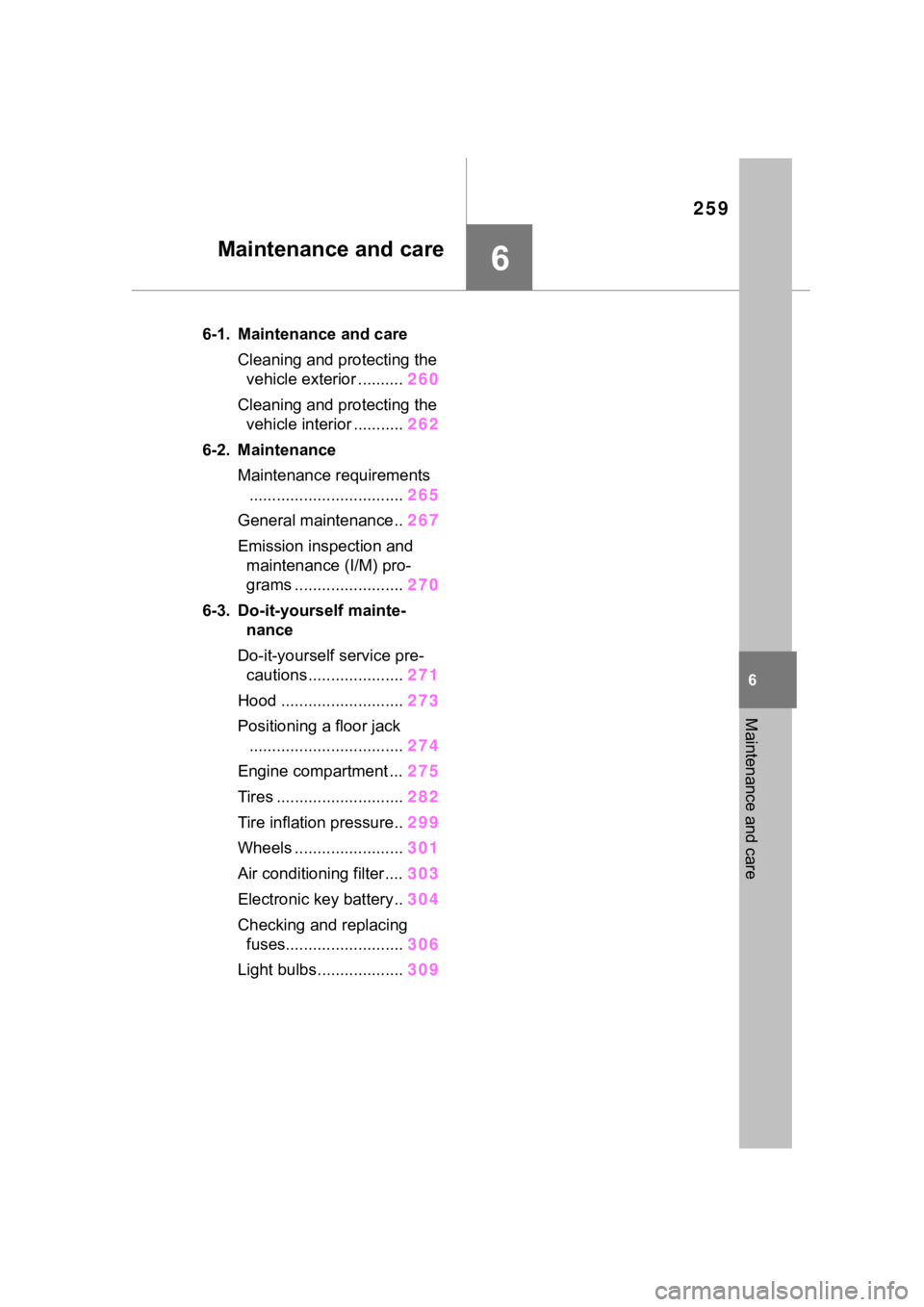
.6-1. Maintenance and careCleaning and protecting the vehicle exterior .......... 260
Cleaning and protecting the vehicle interior ........... 262
6-2. Maintenance Maintenance requirements.................................. 265
General maintenance.. 267
Emission inspection and maintenance (I/M) pro-
grams ........................ 270
6-3. Do-it-yourself mainte- nance
Do-it-yourself service pre- cautions ..................... 271
Hood ........................... 273
Positioning a floor jack .................................. 274
Engine compartment ... 275
Tires ............................ 282
Tire inflation pressure.. 299
Wheels ......... ...............301
Air conditioning filter .... 303
Electronic key battery.. 304
Checking and replacing fuses.......................... 306
Light bulbs................... 309
Page 265 of 436
2656-2. Maintenance
6
Maintenance and care
6-2.Maintenance
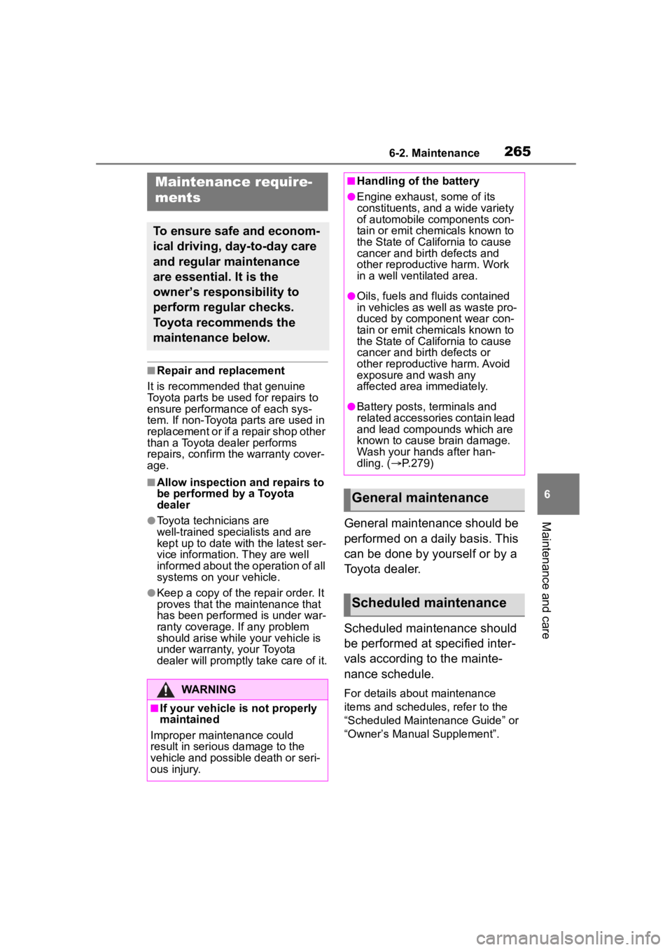
■Repair and replacement
It is recommended that genuine
Toyota parts be used for repairs to
ensure performanc e of each sys-
tem. If non-Toyota parts are used in
replacement or if a repair shop other
than a Toyota dealer performs
repairs, confirm the warranty cover-
age.
■Allow inspection and repairs to
be performed by a Toyota
dealer
●Toyota technicians are
well-trained specialists and are
kept up to date with the latest ser-
vice information. They are well
informed about the operation of all
systems on your vehicle.
●Keep a copy of the repair order. It
proves that the maintenance that
has been performed is under war-
ranty coverage. If any problem
should arise while your vehicle is
under warranty, your Toyota
dealer will promptly take care of it.
General maintenance should be
performed on a daily basis. This
can be done by yourself or by a
Toyota dealer.
Scheduled maintenance should
be performed at specified inter-
vals according to the mainte-
nance schedule.
For details about maintenance
items and schedules, refer to the
“Scheduled Maintenance Guide” or
“Owner’s Manual Supplement”.
Maintenance require-
ments
To ensure safe and econom-
ical driving, day-to-day care
and regular maintenance
are essential. It is the
owner’s responsibility to
perform regular checks.
Toyota recommends the
maintenance below.
WARNING
■If your vehicle is not properly
maintained
Improper maintenance could
result in serious damage to the
vehicle and possible death or seri-
ous injury.
■Handling of the battery
●Engine exhaust, some of its
constituents, and a wide variety
of automobile components con-
tain or emit chemicals known to
the State of California to cause
cancer and birth defects and
other reproductive harm. Work
in a well ventilated area.
●Oils, fuels and fluids contained
in vehicles as well as waste pro-
duced by component wear con-
tain or emit chemicals known to
the State of California to cause
cancer and birth defects or
other reproductive harm. Avoid
exposure and wash any
affected area immediately.
●Battery posts, terminals and
related accessories contain lead
and lead compounds which are
known to cause brain damage.
Wash your hands after han-
dling. ( P.279)
General maintenance
Scheduled maintenance