o2 sensor TOYOTA HIGHLANDER 2001 Service User Guide
[x] Cancel search | Manufacturer: TOYOTA, Model Year: 2001, Model line: HIGHLANDER, Model: TOYOTA HIGHLANDER 2001Pages: 2572, PDF Size: 34.8 MB
Page 232 of 2572

2005 HIGHLANDER (EWD592U)
71
Charge
2 A 1
BR W- L LGPB
73C 43A
11K 10 1G5
A IC37. 5A
ECU- B
2A 4 13 1K 10A
HEATER
R
11 A
IB 3B 12
3K 2
BR
B 9
SB GR
IL2 1 GR
B 2B1
A 2A1
MPX2 22
MPX1 24
BR BR
A17MPX-
MPX+
MPD2
MPD1B 2A 9
BR
BR
RG 5
4 11V
(
*1)
G
(
*1)
G
(
*2)
A 213J 12
3E 1
G
G Y
7V
* 1 : w/ Navigation System
* 2 : w/o Navigation System
IL2 12From Power Source System (
See Page 62)
C11(
A)
, C12(
B)
A10(
A)
, A11(
B) S30(
A)
, S31(
B)
A/C Control Assembly
Airbag Sensor AssemblyCombination Meter
Gat ew ay ECU Short Connector
Page 240 of 2572
'05 HIGHLANDER_U (L/O 0409)
11 6
2005 HIGHLANDER from Nov. '04 Prod. (OM48570U)
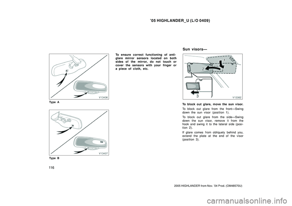
Ty p e A
Ty p e B
To ensure correct functioning of anti-
glare mirror sensors located on both
sides of the mirror, do not touch or
cover the sensors with your finger or
a piece of cloth, etc.
To block out glare, move the sun visor.
To block out glare from the frontÐSwing
down the sun visor (position 1).
To block out glare from the sideÐSwing
down the sun visor, remove it from the
hook and swing it to the lateral side (posi-
tion 2).
If glare comes from obliquely behind you,
extend the plate at the end of the visor
(position 3).
Sun visorsÐ
Page 245 of 2572
2005 HIGHLANDER (EWD592U)
76
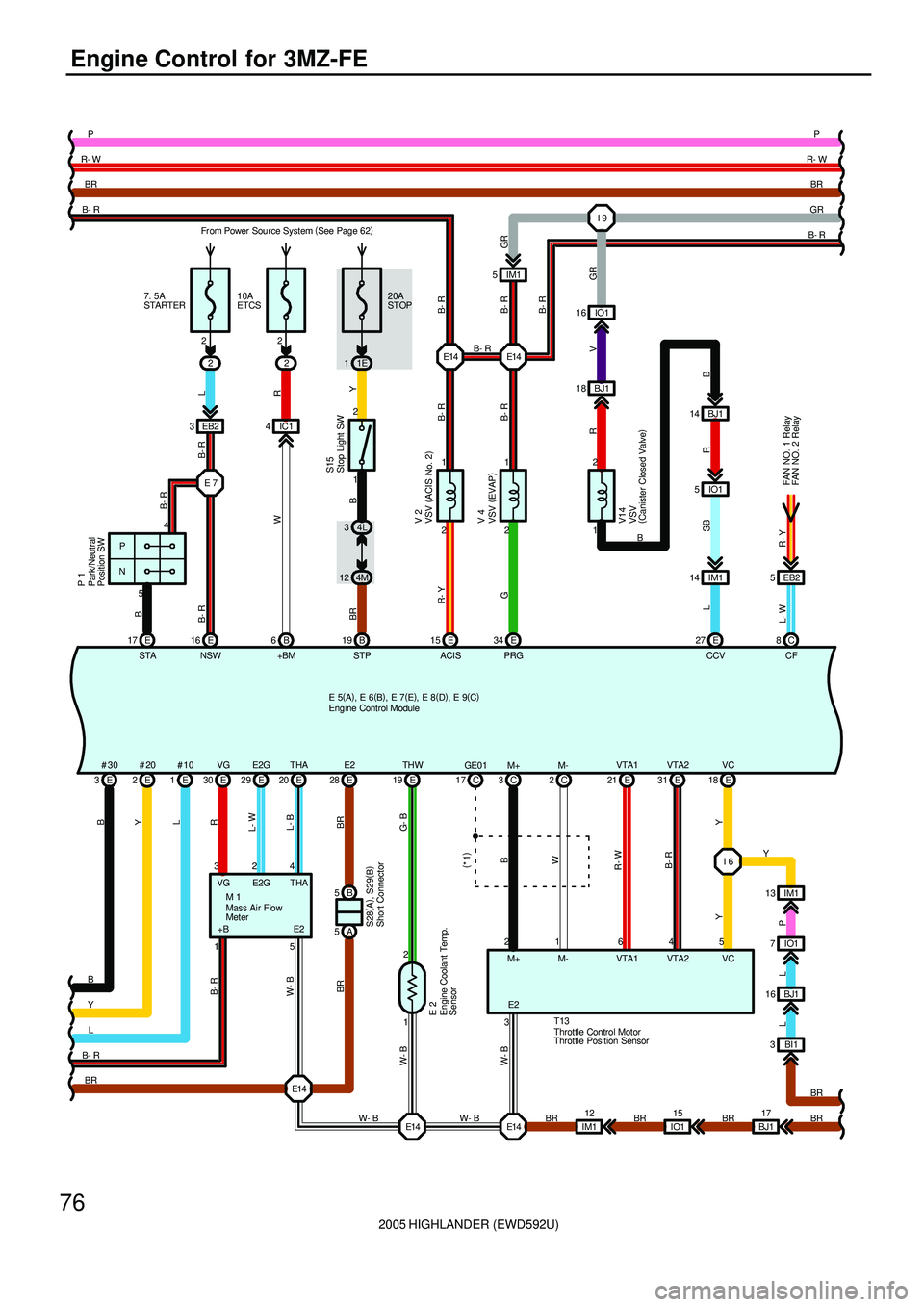
Engine Control for 3MZ-FE
14 BJ1 I 9
2
18 BJ1 IM1
5IO1 2
E 3E2E1E 16
B
Y
L
NSW
#30 #20 #10
B- R
E 17
STA
B
R- W
516 IO1
RR
V14
B
4
NPGR
R
W- B BR BR
P
12
IM1
V
7. 5A
STARTER
W- B
E147IO1
L- B
THA1E14 E14B- R
4 20 E20A
STOP
1E 1
2 1
2 1
E 29 E 30
5 1 32
B- R B- R
E2G VGPRG ACIS STP
G R- Y BR Y
B- R B- R L- WR B- R
E14I 6
1 2C 2E21 E18 E 19
16 5Y VTA1 VC THW
LG- B
Y R- WW
YV 2S15
M 1
T13
W- B
W- B
W- B
C 8
FAN NO. 1 Relay
CF E 34 E 15 B 19
IM1 13 2
4M 124L 3 IC1
L- W
M-
B- R
1 2
CCVE 27SB L
R- Y
15
IO1
B
EB2 3425
10A
ETCS
W
+BM 6B2
Y
LE 7
B- R L B- R P 1
GR B- RGR
R- W
16 BJ1 B
B- R
B- R
BR
E14 BRBR
B 5
A 5E 28E2
BR BR
BP P
5 EB2
BR BR E 31
4 VTA2
B- R
C 3
2
B
M+
3E2 M+ M- VTA1 VTA2 VC C 17GE0 1
(
*1)
IM1 14
L
BI1 3
BJ117
BR Fr om Power Source System (
See Page 62)
FAN NO. 2 Relay
E 5(
A)
, E 6(
B)
, E 7(
E)
, E 8(
D)
, E 9(
C)
S28(
A)
, S29(
B)
Engine Control Module
Mass Air Flow
Meter
Park/Neutral
Position SW
Stop Light SW
Short Connector
Throttle Control Motor
VSV (
ACIS No. 2)
VSV
(
Canister Closed Valve) VSV (
EVAP) V 4 Engine Coolant Temp.
Sensor E 2
VG E2G THA
+B E2
Throttle Position Sensor
Page 246 of 2572
2005 HIGHLANDER (EWD592U)
77
T14IM1 2
1BI1
G- R
1
L
27
Y
12 BJ1(
*1) R- W R- W
A 21C 10
1
3A
VCP24 2
21 3
PSWHT1B OX1B
R- WL
BR
B
VPA2A
WBR
23
H10 W B
D 25 D21
R- Y
W
B 26 B 27
67IMO IMI
V B
W- R
IGF1
24 E3 1
2
2 1C 16 C15
2 1C 14 C13 1
2
G- W
L- R G- R
G- B
OC1+ OC1- OC2+ OC2-
W
R
NT+D 27
NT-D 35
NC+D 26
NC-D 34
W- G R- W
Ignition Coil and Igniters
EFIO EFIIB 2ACMG
O
MG CLT Relay
PTNK
IO1 3 GR
IM1 2
6IM1 * 1 : Shielded
3
(
*1)BR BR
29 A
EPA2
B
22 A
VPA EPAA 28
R
B- R
156 EPA2 VPA2 VCP2 EPA VPA
G
26 A
VCPA4 VCPA A27
3 14 2
HT2B OX2B
BR B- R
D 33 D29
W- L
B
E14(
*1)
BR
(
*1)
P P
A 12ELS2
G
IA1 7
5
EXCD
BR BR
GR H 6
BI1 2
Y
G
(
*2)(
*2)
* 2 : w/ Rear Seat Entertainment System
E 5(
A)
, E 6(
B)
, E 7(
E)
, E 8(
D)
, E 9(
C) Accel Position Sensor
Engine Control Module
Heated Oxygen Sensor
(
Bank 2 Sensor 2)
Heated Oxygen Sensor
(
Bank 1 Sensor 2)
Transponder Key
Computer
Tur bine Speed Sensor T 3
Counter Gear Speed
Sensor C 6
Voltage Inverter V15 Power Steering Oil
Pressure SW P 2 Camshaft Timing Oil
Contr ol Valve LH C 3 Camshaft Timing Oil
Contr ol Valve RH C 4 Vapor Pressure Sensor V11
+B E1 E2 +B
HT OX HT1B OX1B
PTNK
VCC GND
Page 247 of 2572

2005 HIGHLANDER (EWD592U)
78
Engine Control for 3MZ-FE
G 14C RL
21
L
W- G
E16
6 EB1
A2A-
P
EB1
D 5D43 14 2 (
*1)
(
*1) (
*1) (
*1)
HA1A A2A+
R- W B- R
(
*1) (
*1)
A 7
HA2A A1A- A1A+ 3
D 22 D30
BR
Y
D 23 D31
L
R- W
R- L
IGT1
8E
P
IGT2
9E
Y- B
IGT3
10 E
L- Y
IGT4
11 E
G- Y
IGT5
12 E
L- R
IGT6
13 E
Ignition Coil
and Igniters
G
TRC+
31 A
Y
TRC-
25 A
Skid Control ECU
with Actuator
R- W R- W(
*1)
V 7
L
(
*1)
(
*1) (
*1)
2 1
(
*1)
2
1
V 6
C 7
6D
I 6 E05I 6
26 C
L
R
I 6
ECE 6C7 E 7 C 22E04
7
ED D
W- B
W- B
W- B
GGR
MOPS E01 E02 E03
(
*1)
B- W W- B W- B
W- B
G
C 25 C24 C27
(
*1)
1
O 1
Y- B
VV2+ NE+ NE- VV1+2
1 3 14 2
B- W B- RA 6
(
*1)R- W
BRP P
C 4
W- B
ME01
I 6
W- B
E 5(
A)
, E 6(
B)
, E 7(
E)
, E 8(
D)
, E 9(
C)
Air Fuel Ratio Sensor
(
Bank 1 Sensor 1)
Air Fuel Ratio Sensor
(
Bank 2 Sensor 1)
Crankshaft Position
Sensor
Engine Control Module
Generator
Oil Pressure SW
VVT Sensor LH
VVT Sensor RH
HT AF+ HT AF++B AF- +B AF-
Page 248 of 2572
2005 HIGHLANDER (EWD592U)
79
A TCA A 20
ENG+ NEOA 17 A24
ENG-A 30
B
V
RSkid Control
ECU with Actuator
EOM
A 15
(
*1)
(
*1)
(
*1)
D 1
2
R
KNK2
(
*1)
(
*1)
BR
BR
(
*1)
(
*1)
(
*1) (
*1)
W
P
KNK1
B
D
2 2A
A 4LR
A29MPX2
11W
L B 5TACHI 8
EA1 4 EA13 EA11 EA1 2
11B 18 D 28 D 20 (
*1)
(
*1)
WG
WG
BR V
EKN2 EKNK MPX1
(
*1)
SIL
B R
GR K 3
K 2
GR A 19 A18
(
*1) SB
(
*1)
A
AA
WF SE
AIM1 4
R
(
*1)
R
(
*1)
O
AAA
(
*1)
(
*1)
B
J 7 6 12 4A
17SPD
Y
B
BRO
V
P
W- B
B
Y
W
W- B
P P
L
Y
* 1 : Shielded
E1E 1
BR
BR
A
E 5(
A)
, E 6(
B)
, E 7(
E)
, E 8(
D)
, E 9(
C)
Engine Contr ol ModuleJunction Connector
Knock Sensor
(
Bank 1) Knock Sensor
(
Bank 2)
IL2 10 IL29
Page 249 of 2572
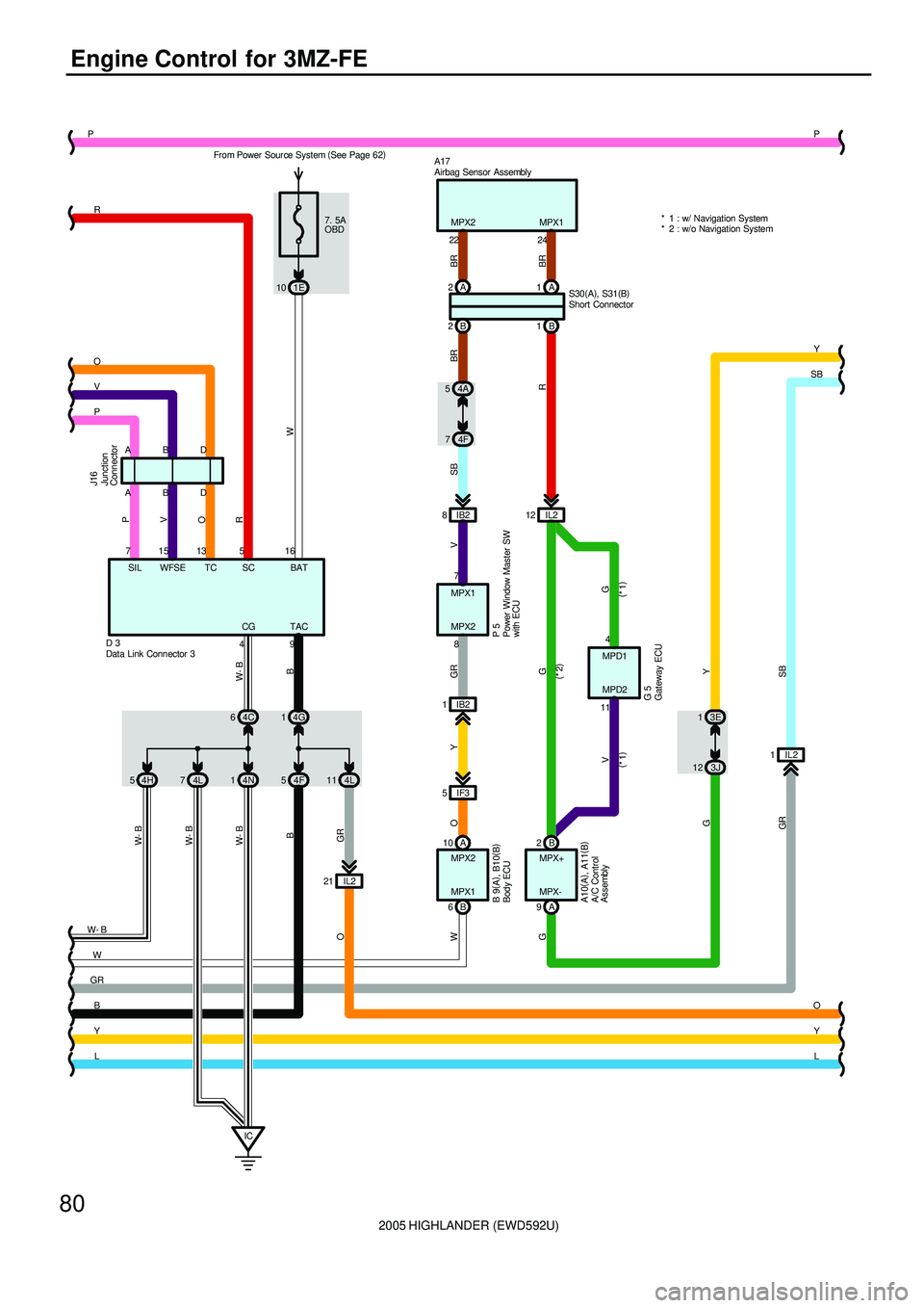
2005 HIGHLANDER (EWD592U)
80
Engine Control for 3MZ-FE
A
AB
B
9TAC
4G 1A 2
WBA
1B
16 75
IC21 IL2MPX1
74L 114L54F
R SB
14N 64C7
1IL2
B 2 12 IL2
GR1
74F
8IB2
1IB2
5IF3
B 68
10 A 10 1E7. 5A
OBD
MPX+ MPX2
W
MPX2
MPX1
W- B
W- B
B
GR O
SB GR
SC SIL BAT
CG
4
W- B
V
G Y OGR
P 5
LY
SB
Y
L O 2B P
4AP
54H
W- B
D
D
15
J16
5
WFSE13
TC
P
11MPD14
MPD2 D 3G 5G
MPX-
V
9A
GV
O
R
W
R
O
V
P
W- B
B
Y
BR BR
BR
22MPX2
24MPX1 A17
(
*2)
(
*1) (
*1)
3E 1
3J 12
GY
* 1 : w/ Navigation System
* 2 : w/o Navigation System From Power Sour ce System (
See Page 62)
S30(
A)
, S31(
B)
A10(
A)
, A11(
B) B 9(
A)
, B10(
B)
A/C Control
Assembly
Airbag Sensor Assembly
Body ECU
Data Link Connector 3
Gateway ECUJunction
Connector
Power Window Master SW
with ECU
Short Connector
Page 251 of 2572
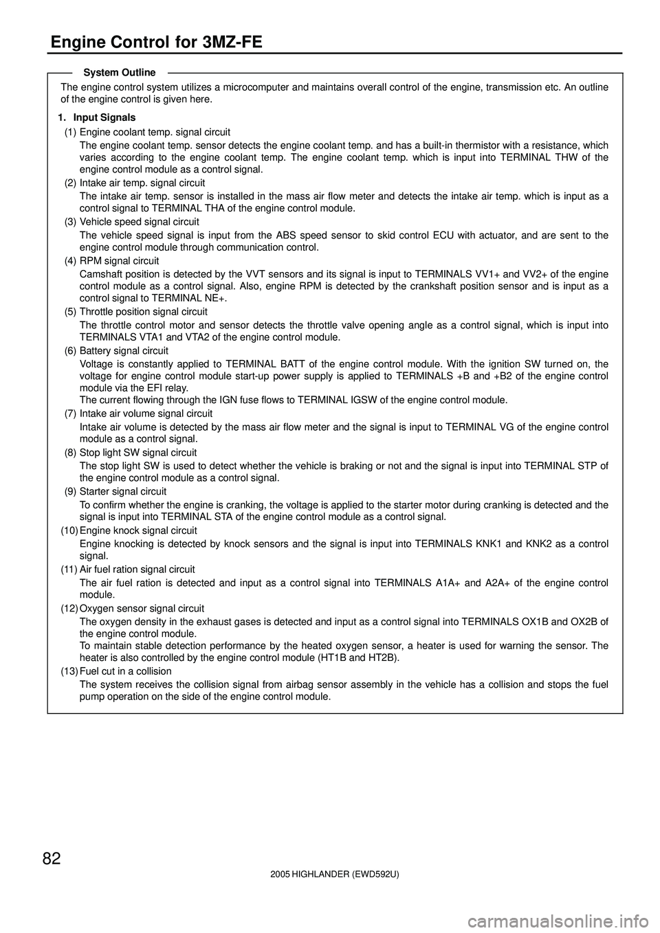
2005 HIGHLANDER (EWD592U)
82
Engine Control for 3MZ-FE
The engine control system utilizes a microcomputer and maintains overall control of the engine, transmission etc. An outline
of the engine control is given here.
1. Input Signals
(1) Engine coolant temp. signal circuit
The engine coolant temp. sensor detects the engine coolant temp. and has a built-in thermistor with a resistance, which
varies according to the engine coolant temp. The engine coolant temp. which is input into TERMINAL THW of the
engine control module as a control signal.
(2) Intake air temp. signal circuit
The intake air temp. sensor is installed in the mass air flow meter and detects the intake air temp. which is input as a
control signal to TERMINAL THA of the engine control module.
(3) Vehicle speed signal circuit
The vehicle speed signal is input from the ABS speed sensor to skid control ECU with actuator, and are sent to the
engine control module through communication control.
(4) RPM signal circuit
Camshaft position is detected by the VVT sensors and its signal is input to TERMINALS VV1+ and VV2+ of the engine
control module as a control signal. Also, engine RPM is detected by the crankshaft position sensor and is input as a
control signal to TERMINAL NE+.
(5) Throttle position signal circuit
The throttle control motor and sensor detects the throttle valve opening angle as a control signal, which is input into
TERMINALS VTA1 and VTA2 of the engine control module.
(6) Battery signal circuit
Voltage is constantly applied to TERMINAL BATT of the engine control module. With the ignition SW turned on, the
voltage for engine control module start-up power supply is applied to TERMINALS +B and +B2 of the engine control
module via the EFI relay.
The current flowing through the IGN fuse flows to TERMINAL IGSW of the engine control module.
(7) Intake air volume signal circuit
Intake air volume is detected by the mass air flow meter and the signal is input to TERMINAL VG of the engine control
module as a control signal.
(8) Stop light SW signal circuit
The stop light SW is used to detect whether the vehicle is braking or not and the signal is input into TERMINAL STP of
the engine control module as a control signal.
(9) Starter signal circuit
To confirm whether the engine is cranking, the voltage is applied to the starter motor during cranking is detected and the
signal is input into TERMINAL STA of the engine control module as a control signal.
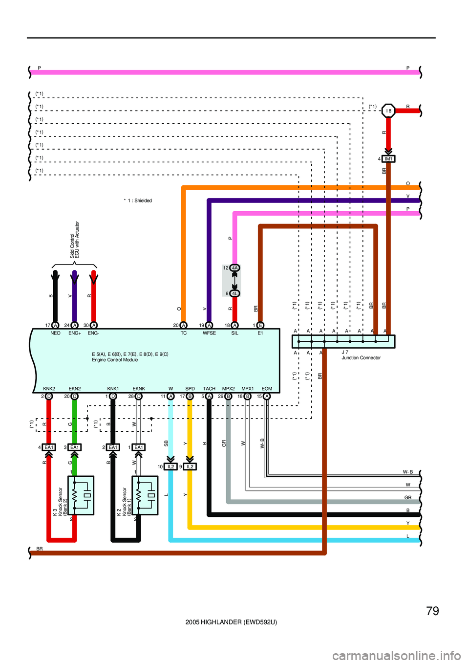
(10) Engine knock signal circuit
Engine knocking is detected by knock sensors and the signal is input into TERMINALS KNK1 and KNK2 as a control
signal.
(11) Air fuel ration signal circuit
The air fuel ration is detected and input as a control signal into TERMINALS A1A+ and A2A+ of the engine control
module.
(12) Oxygen sensor signal circuit
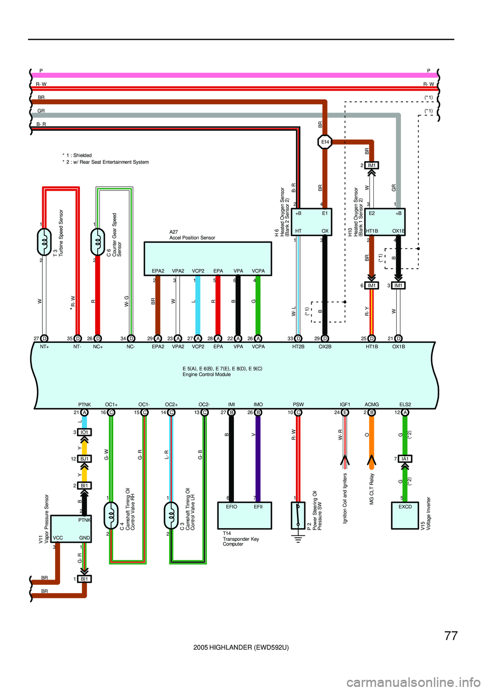
The oxygen density in the exhaust gases is detected and input as a control signal into TERMINALS OX1B and OX2B of
the engine control module.
To maintain stable detection performance by the heated oxygen sensor, a heater is used for warning the sensor. The
heater is also controlled by the engine control module (HT1B and HT2B).
(13) Fuel cut in a collision
The system receives the collision signal from airbag sensor assembly in the vehicle has a collision and stops the fuel
pump operation on the side of the engine control module.
System Outline
Page 252 of 2572
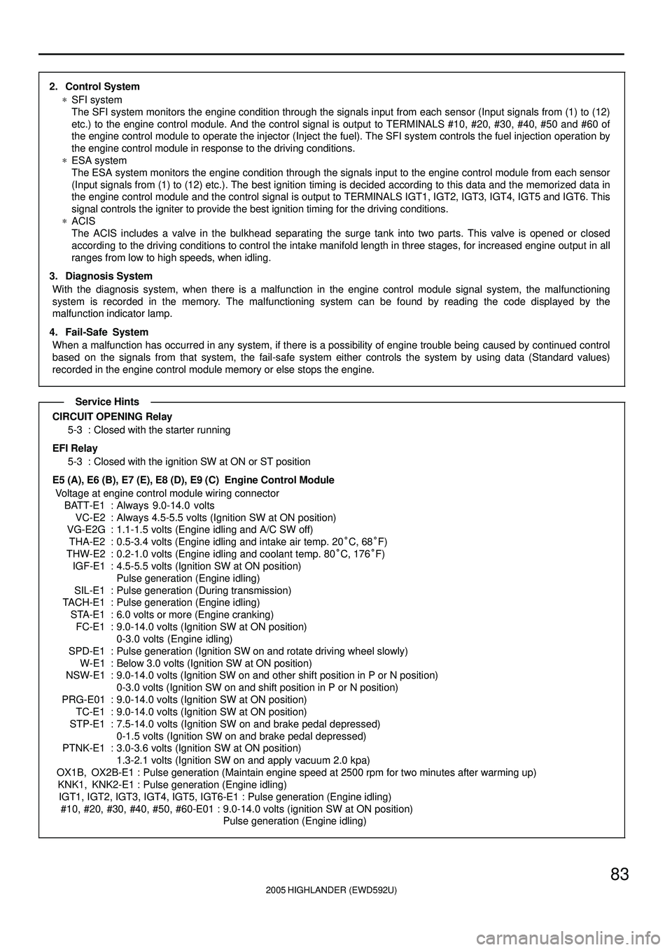
2005 HIGHLANDER (EWD592U)
83
2. Control System
*SFI system
The SFI system monitors the engine condition through the signals input from each sensor (Input signals from (1) to (12)
etc.) to the engine control module. And the control signal is output to TERMINALS #10, #20, #30, #40, #50 and #60 of
the engine control module to operate the injector (Inject the fuel). The SFI system controls the fuel injection operation by
the engine control module in response to the driving conditions.
*ESA system
The ESA system monitors the engine condition through the signals input to the engine control module from each sensor
(Input signals from (1) to (12) etc.). The best ignition timing is decided according to this data and the memorized data in
the engine control module and the control signal is output to TERMINALS IGT1, IGT2, IGT3, IGT4, IGT5 and IGT6. This
signal controls the igniter to provide the best ignition timing for the driving conditions.
*ACIS
The ACIS includes a valve in the bulkhead separating the surge tank into two parts. This valve is opened or closed
according to the driving conditions to control the intake manifold length in three stages, for increased engine output in all
ranges from low to high speeds, when idling.
3. Diagnosis System
With the diagnosis system, when there is a malfunction in the engine control module signal system, the malfunctioning
system is recorded in the memory. The malfunctioning system can be found by reading the code displayed by the
malfunction indicator lamp.
4. Fail-Safe System
When a malfunction has occurred in any system, if there is a possibility of engine trouble being caused by continued control
based on the signals from that system, the fail-safe system either controls the system by using data (Standard values)
recorded in the engine control module memory or else stops the engine.
CIRCUIT OPENING Relay
5-3 : Closed with the starter running
EFI Relay
5-3 : Closed with the ignition SW at ON or ST position
E5 (A), E6 (B), E7 (E), E8 (D), E9 (C) Engine Control Module
Voltage at engine control module wiring connector
BATT-E1 : Always 9.0-14.0 volts
VC-E2 : Always 4.5-5.5 volts (Ignition SW at ON position)
VG-E2G : 1.1-1.5 volts (Engine idling and A/C SW off)
THA-E2 : 0.5-3.4 volts (Engine idling and intake air temp. 20°C, 68°F)
THW-E2 : 0.2-1.0 volts (Engine idling and coolant temp. 80°C, 176°F)
IGF-E1 : 4.5-5.5 volts (Ignition SW at ON position)
Pulse generation (Engine idling)
SIL-E1 : Pulse generation (During transmission)
TACH-E1 : Pulse generation (Engine idling)
STA-E1 : 6.0 volts or more (Engine cranking)
FC-E1 : 9.0-14.0 volts (Ignition SW at ON position)
0-3.0 volts (Engine idling)
SPD-E1 : Pulse generation (Ignition SW on and rotate driving wheel slowly)
W-E1 : Below 3.0 volts (Ignition SW at ON position)
NSW-E1 : 9.0-14.0 volts (Ignition SW on and other shift position in P or N position)
0-3.0 volts (Ignition SW on and shift position in P or N position)
PRG-E01 : 9.0-14.0 volts (Ignition SW at ON position)
TC-E1 : 9.0-14.0 volts (Ignition SW at ON position)
STP-E1 : 7.5-14.0 volts (Ignition SW on and brake pedal depressed)
0-1.5 volts (Ignition SW on and brake pedal depressed)
PTNK-E1 : 3.0-3.6 volts (Ignition SW at ON position)
1.3-2.1 volts (Ignition SW on and apply vacuum 2.0 kpa)
OX1B, OX2B-E1 : Pulse generation (Maintain engine speed at 2500 rpm for two minutes after warming up)
KNK1, KNK2-E1 : Pulse generation (Engine idling)
IGT1, IGT2, IGT3, IGT4, IGT5, IGT6-E1 : Pulse generation (Engine idling)
#10, #20, #30, #40, #50, #60-E01 : 9.0-14.0 volts (ignition SW at ON position)
Pulse generation (Engine idling)
Service Hints
Page 254 of 2572
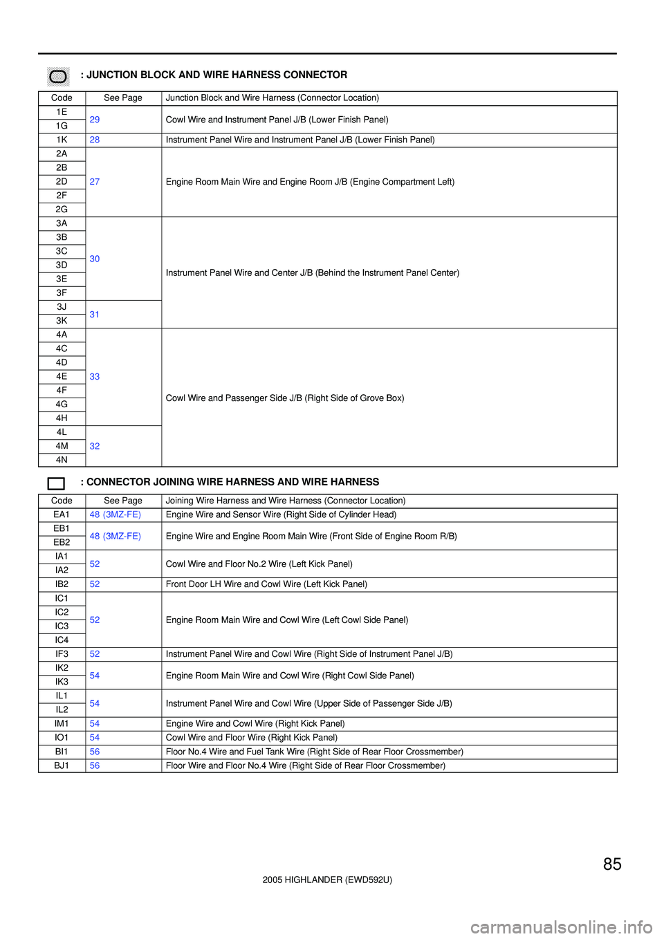
2005 HIGHLANDER (EWD592U)
85
������ ���: JUNCTION BLOCK AND WIRE HARNESS CONNECTOR
CodeSee PageJunction Block and Wire Harness (Connector Location)
1E29Cowl Wire and Instrument Panel J/B (Lower Finish Panel)1G29Cowl Wire and Instrument Panel J/B (Lower Finish Panel)
1K28Instrument Panel Wire and Instrument Panel J/B (Lower Finish Panel)
2A
2B
2D27Engine Room Main Wire and Engine Room J/B (Engine Compartment Left)
2F
gg(g)
2G
3A
3B
3C303D30
Instrument Panel Wire and Center J/B (Behind the Instrument Panel Center)3EInstrument Panel Wire and Center J/B (Behind the Instrument Panel Center)
3F
3J313K31
4A
4C
4D
4E33
4FCowl Wire and Passenger Side J/B (Right Side of Grove Box)4GCowl Wire and Passenger Side J/B (Right Side of Grove Box)
4H
4L
4M32
4N
: CONNECTOR JOINING WIRE HARNESS AND WIRE HARNESS
CodeSee PageJoining Wire Harness and Wire Harness (Connector Location)
EA148 (3MZ-FE)Engine Wire and Sensor Wire (Right Side of Cylinder Head)
EB148 (3MZ FE)Engine Wire and Engine Room Main Wire (Front Side of Engine Room R/B)EB248 (3MZ-FE)Engine Wire and Engine Room Main Wire (Front Side of Engine Room R/B)
IA152Cowl Wire and Floor No 2 Wire (Left Kick Panel)IA252Cowl Wire and Floor No.2 Wire (Left Kick Panel)
IB252Front Door LH Wire and Cowl Wire (Left Kick Panel)
IC1
IC252Engine Room Main Wire and Cowl Wire (Left Cowl Side Panel)IC352Engine Room Main Wire and Cowl Wire (Left Cowl Side Panel)
IC4
IF352Instrument Panel Wire and Cowl Wire (Right Side of Instrument Panel J/B)
IK254Engine Room Main Wire and Cowl Wire (Right Cowl Side Panel)IK354Engine Room Main Wire and Cowl Wire (Right Cowl Side Panel)
IL154Instrument Panel Wire and Cowl Wire (Upper Side of Passenger Side J/B)IL254Instrument Panel Wire and Cowl Wire (Upper Side of Passenger Side J/B)
IM154Engine Wire and Cowl Wire (Right Kick Panel)
IO154Cowl Wire and Floor Wire (Right Kick Panel)
BI156Floor No.4 Wire and Fuel Tank Wire (Right Side of Rear Floor Crossmember)
BJ156Floor Wire and Floor No.4 Wire (Right Side of Rear Floor Crossmember)