o2 sensor TOYOTA HIGHLANDER 2001 Service Service Manual
[x] Cancel search | Manufacturer: TOYOTA, Model Year: 2001, Model line: HIGHLANDER, Model: TOYOTA HIGHLANDER 2001Pages: 2572, PDF Size: 34.8 MB
Page 476 of 2572

2005 HIGHLANDER (EWD592U)
161
The SRS is a driver and front passenger protection device which has a supplemental role to the seat belts.
When the ignition SW is turned to ON, the current from the IGN fuse flows to TERMINAL (B) 5 of the airbag sensor
assembly.
If an accident occurs while driving, when the frontal impact exceeds a set level, the current from the IGN fuse flows to
TERMINALS (B) 14, (B) 16, (B) 10, (B) 8, (A) 8 (w/ curtain shield airbag), or (A) 2 (w/o curtain shield airbag) and (C) 9 (w/
curtain shield airbag), or (C) 5 (w/o curtain shield airbag) of the airbag sensor assembly to the airbag squibs and the
pretensioners to TERMINALS (B) 13, (B) 17, (B) 11, (B) 7, (A) 7 (w/ curtain shield airbag), or (A) 1 (w/o curtain shield airbag)
and (C) 10 (w/ curtain shield airbag), or (C) 6 (w/o curtain shield airbag) of the airbag sensor assembly to TERMINAL (B) 27,
(B) 28 or BODY GROUND to GROUND, so that current flows to the airbag squibs and the pretensioners and causes them to
operate.
When the side impact also exceeds a set level, the current from the IGN fuse flows to TERMINALS (A) 12, (C) 5, (A) 9 and
(C) 8 of the airbag sensor assembly to the side airbag squibs and the curtain shield airbag squibs TERMINALS (A) 11, (C) 6,
(A) 10 and (C) 7 of the airbag sensor assembly to TERMINAL (B) 27, (B) 28 or BODY GROUND to GROUND, causing side
airbag squibs and curtain shield airbag squibs to operate.
The airbag stored inside the steering wheel pad is instantaneously expanded to soften the shock to the driver.
The airbag stored inside the passenger's instrument panel is instantaneously expanded to soften the shock to the front
passenger.
Side airbags are instantaneously expanded to soften the shock of side to the driver and front passenger.
The curtain shield airbag can ease an impact on the head of the front and rear passengers and reduce risks of injury.
In a head-on crash, the driver moves forward and may strike his/her lower limbs against the instrument panel, the key
cylinder, etc.
The pretensioners make sure of the seat belt restrainability.
: PARTS LOCATION
CodeSee PageCodeSee PageCodeSee Page
A838 (3MZ-FE)C1844O1047 (w/o Power Seat)A840 (2AZ-FE)C1944O1146 (w/ Power Seat)
A938 (3MZ-FE)D342O1147 (w/o Power Seat)A940 (2AZ-FE)E542P544
A10A42G543P1344
A11B42J643P1444
A16A42J1643S1645
A17B42J1743S1745
A18C42J1844S1846 (w/ Power Seat)
A1942O6A46 (w/ Power Seat)S1847 (w/o Power Seat)
A2042O6A47 (w/o Power Seat)S1946 (w/ Power Seat)
B9A42O7B46 (w/ Power Seat)S1947 (w/o Power Seat)
B10B42O7B47 (w/o Power Seat)S30A43
B1746 (w/ Power Seat)O846 (w/ Power Seat)S31B43B1747 (w/o Power Seat)O847 (w/o Power Seat)S3245
B1946 (w/ Power Seat)O946 (w/ Power Seat)S3345
C11A42O947 (w/o Power Seat)T1543
C12B42O1046 (w/ Power Seat)
System Outline
Page 480 of 2572
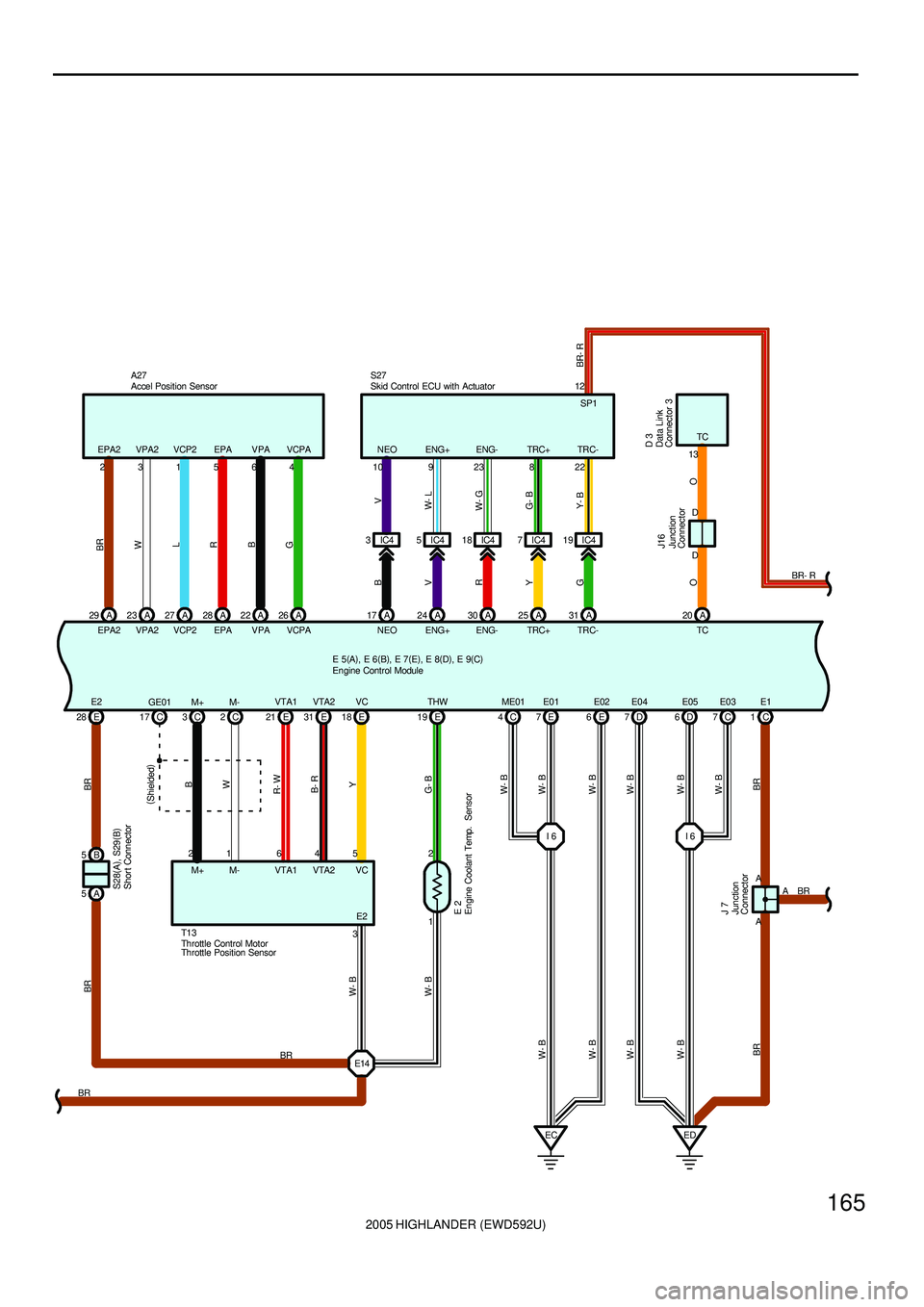
2005 HIGHLANDER (EWD592U)
165
W- B W- B
W- B
W- B W- B
W- B
BR G- BY BR
7C
EC ED6E 7E 6D 1CD 7E03
W- B
W- B
A
A
BR
B- R
VC
3 5
VTA2
1 2
E14 E 28 E18 E19
VTA1
BRE 2
4 E2 VC THW E04 E1E05 E01 E02
I 6 E 31VTA2
R- W
6E 21VTA1
BR
A 5B 5
E2
W- B
W- B W- BL
27 A
VCP2 VPA2A 23
W
23
BR
29 A
EPA2
B
22 A
VPA EPAA 28
R
156 EPA2 VPA2 VCP2 EPA VPA
G
26 A
VCPA4 VCPA A27
ENG+ NEOA 17 A24
ENG-A 30
B
V
R
TCA 20
O
D DJ16D 3
O
13TC
10 9 23 8 22NEO ENG+ ENG- TRC+ TRC- S27
IC4 3IC45IC418 IC47IC419
TRC+A 25
Y
TRC-A 31
GV
W- L
W- G
G- B
Y- B
C 2
1
W
M-
C 3
2
B
M+
M+ M- C 17GE01
(
Shielded)
J 7
BR A
W- B
4CME01
I 6
BRE 5(
A)
, E 6(
B)
, E 7(
E)
, E 8(
D)
, E 9(
C)
S28(
A)
, S29(
B)
Accel Position Sensor
Data Link
Connector 3 Engine Coolant Temp. Sensor
Engine Control Module
Junction
ConnectorJunction
Connector
Skid Control ECU with Actuator
Shor t Connector
Throttle Control Motor T1 3
Throttle Position Sensor12
SP1
BR- R
BR- R
Page 481 of 2572
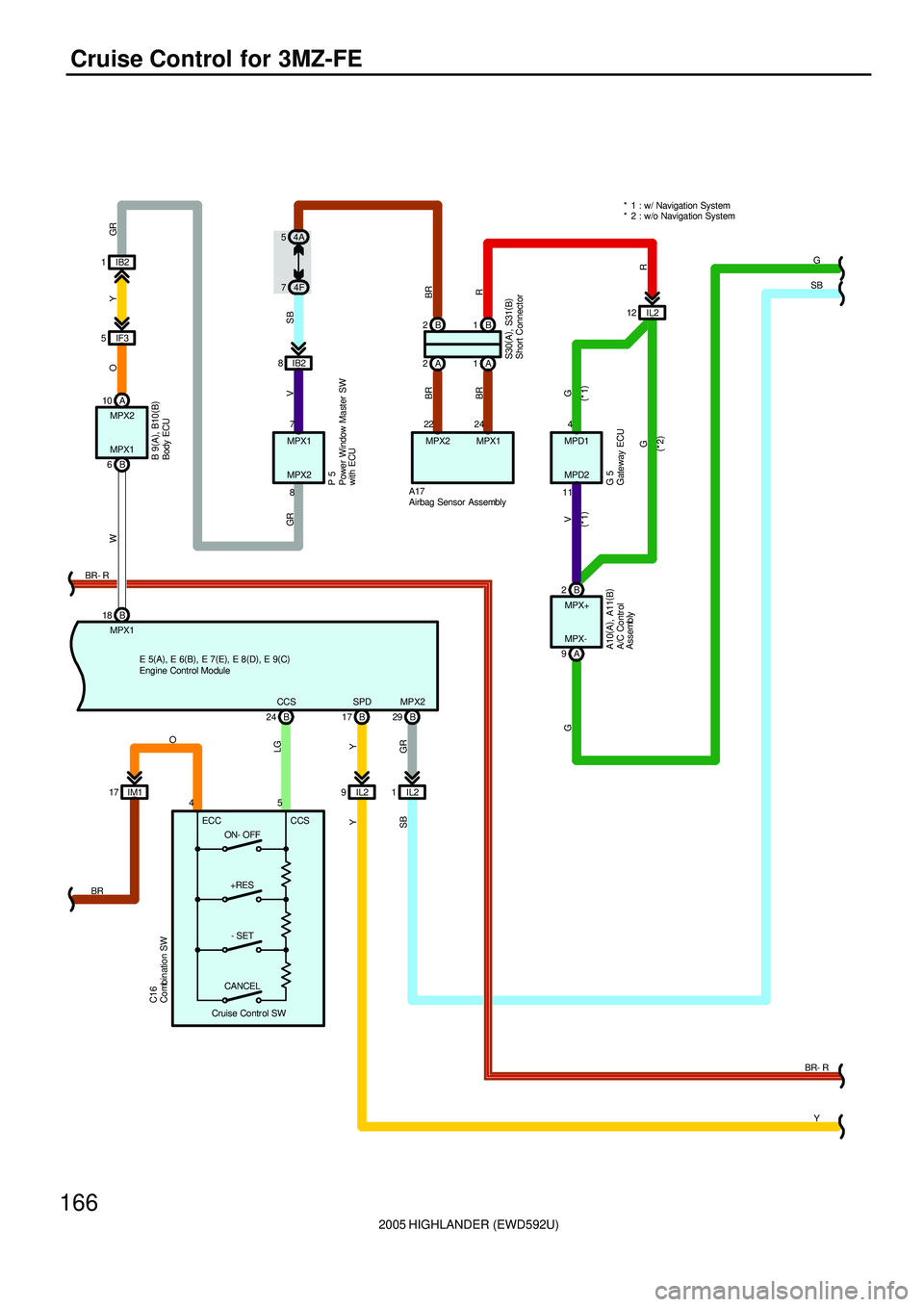
2005 HIGHLANDER (EWD592U)
166
Cruise Control for 3MZ-FE
CCS
LG
AG
SB
B A
MPX1
W
R
10
MPX2
GR
MPX2
VGR Y
29 B MPX1 6
A17
2B IB2 8 IB2 1
IF3 5
O
7
8 MPX1
MPX2
P 5
MPX+ B
Y
SPD
17 B
IL2 9
Y
2B1
A 1 A 2
BR
24
MPX1
BR
22
MPX2
G V
4
11MPD1
MPD2
G 5
IL2 12SB
74F 54A
MPX-
G
9
Y IL2 1
SB
(
*1) (
*1)
G
(
*2)
+RES
- SET
CANCELCCS ECC 45
C16
24 B
ON- OFF IM1 17O
BR
GR
18 B
BR
Cruise Contr ol SW
R
* 1 : w/ Navigation System
* 2 : w/o Navigation System
B 9(
A)
, B10(
B)
S30(
A)
, S31(
B)
A10(
A)
, A11(
B)
E 5(
A)
, E 6(
B)
, E 7(
E)
, E 8(
D)
, E 9(
C)A/C Contr ol
Assembly
Airbag Sensor Assembly
Body ECU Combination SW
Engine Control Module
Gateway ECU Power Window Master SW
with ECU
Short Connector
BR- R BR- R
Page 488 of 2572
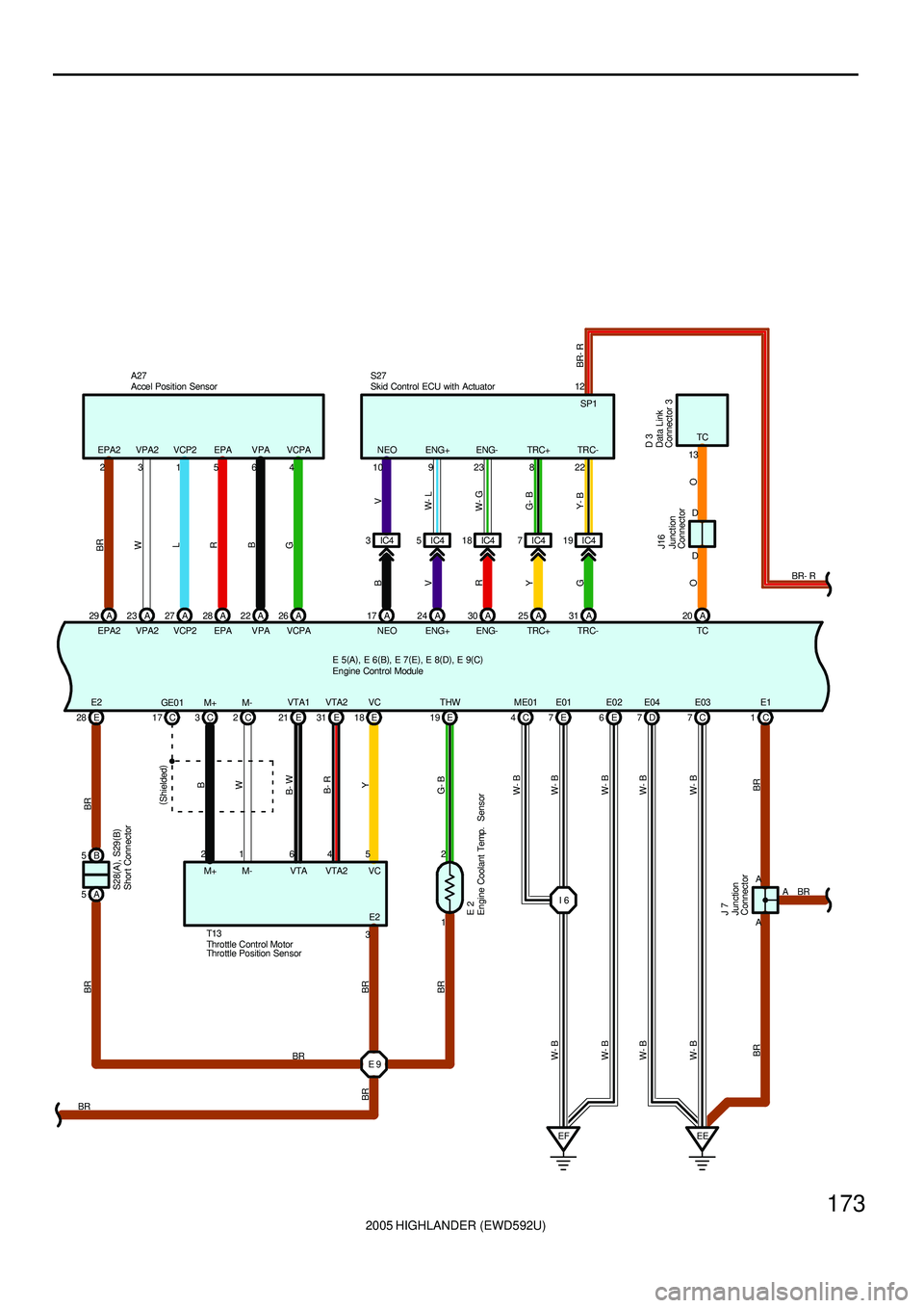
2005 HIGHLANDER (EWD592U)
173
BR BR
W- B
W- B W- B
BR G- BY
7C
EF EE6E 4C 1CD 7E03
W- B W- B
A
A
BR
B- R
VC
3 5
VTA2
1 2
E 9 E 28 E18 E19
VTA
BRE 2
4 E2 VC THW E04 E1ME01 E02
E 31VTA2
B- W
6E 21VTA1
BR
A 5B 5
E2
W- B
W- B W- BL
27 A
VCP2 VPA2A 23
W
23
BR
29 A
EPA2
B
22 A
VPA EPAA 28
R
156 EPA2 VPA2 VCP2 EPA VPA
G
26 A
VCPA4 VCPA A27
ENG+ NEOA 17 A24
ENG-A 30
B
V
R
TCA 20
O
D DJ16D 3
O
13TC
10 9 23 8 22NEO ENG+ ENG- TRC+ TRC- S27
IC4 3IC45IC418 IC47IC419
TRC+A 25
Y
TRC-A 31
GV
W- L
W- G
G- B
Y- B
C 2
1
W
M-
C 3
2
B
M+
M+ M- C 17GE0 1
(
Shielded)
J 7
BR A
BR
BRBR
7EE01
W- B
I 6 E 5(
A)
, E 6(
B)
, E 7(
E)
, E 8(
D)
, E 9(
C)S28(
A)
, S29(
B)
Accel Position Sensor
Data Link
Connector 3 Engine Coolant Temp. Sensor
Engine Control Module
Junction
ConnectorJunction
Connector
Skid Control ECU with Actuator
Shor t Connector
Throttle Control Motor T13
Throttle Position Sensor12
SP1
BR- R
BR- R
Page 489 of 2572
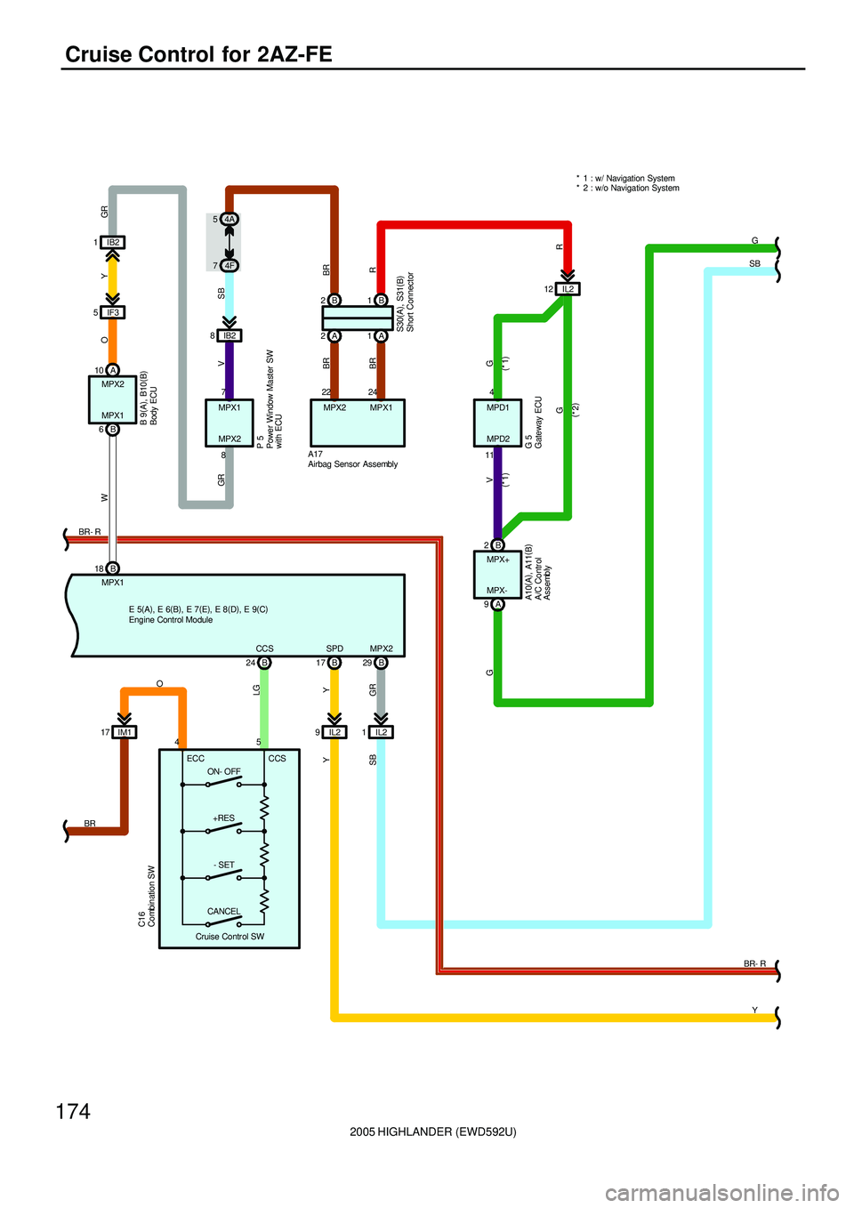
2005 HIGHLANDER (EWD592U)
174
Cruise Control for 2AZ-FE
CCS
LG
AG
SB
B A
MPX1
W
R
10
MPX2
GR
MPX2
VGR Y
29 B MPX1 6
A17
2B IB2 8 IB2 1
IF3 5
O
7
8 MPX1
MPX2
P 5
MPX+ B
Y
SPD
17 B
IL2 9
Y
2B1
A 1 A 2
BR
24
MPX1
BR
22
MPX2
G V
4
11MPD1
MPD2
G 5
IL2 12SB
74F 54A
MPX-
G
9
Y IL2 1
SB
(
*1) (
*1)
G
(
*2)
+RES
- SET
CANCELCCS ECC 45
C16
24 B
ON- OFF IM1 17O
BR
GR
18 B
BR
Cruise Contr ol SW* 1 : w/ Navigation System
* 2 : w/o Navigation System
R S30(
A)
, S31(
B) B 9(
A)
, B10(
B)
E 5(
A)
, E 6(
B)
, E 7(
E)
, E 8(
D)
, E 9(
C)A10(
A)
, A11(
B)
A/C Contr ol
Assembly
Airbag Sensor Assembly
Body ECU Combination SW
Engine Control Module
Gateway ECU Power Window Master SW
with ECU
Short Connector
BR- R
BR- R
Page 495 of 2572
2005 HIGHLANDER (EWD592U)
180
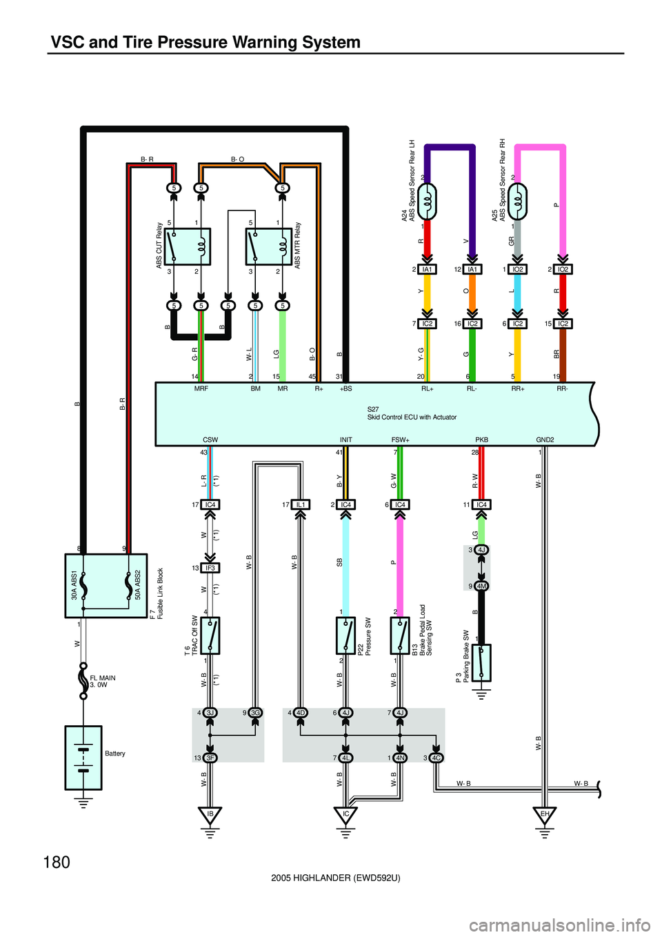
VSC and Tire Pressure Warning System
5
2 5
55IA1 IO2
MR 15 14
MRF1 2
IC2 6IC215
519 31
+BS RR+ RR-
1 2 FSW+
7
4J 3
4M 9
Y
R+ 45
B13
A25
28PKB
O
RL
1
S27
P 3ABS CUT RelayFL MAIN
3. 0W
Battery
WB
B- R
G- W
R- W B
GR
P Y
BRB B- OLG
B- R
2IO2
G- R
12 IA1
V RA24
RL- RL+6 2016 IC2 7IC22
1
Y- G
G
1 43CSW
41INIT
L- R
B- Y W W- B
W- B
IB
W- BT 6
4
121
P22
IC4 17 IC42
3J 44J6
ABS MTR Relay W- L
BM 25
1 89
50A ABS2 30A ABS1
5
5 5 51 51
32 32B- O
B
B
3F 13 4L74J 7
4N 1 4D 4 93G
IC
W- B
IL1 17 IC46
IF3 13
W
W- B
SB
P W- B
W- B W- B
IC4 11
LG
EH
W- B
1 GN D2
W- BF 7
(
*1) (
*1) (
*1) (
*1)
W- B 4C 3
W- B
ABS Speed Sensor Rear LH
ABS Speed Sensor Rear RH Br ake Pedal Load
Sensing SWFusible Link Block
Parking Brake SWPr essure SW
Skid Control ECU with Actuator
TRAC Off SW
Page 496 of 2572

2005 HIGHLANDER (EWD592U)
181
A 5
R- Y
17
FR- 1
2
18 IC4 5IC4 2 1
3IC4
GND1 FL -
32 4
A
EB 10
NEO9
ENG+23
ENG-8
TRC+22
TRC- NEO
17ENG+
24ENG-
30TRC+
25TRC-
31
S27E 5
B
W- B
IC4
O
P
18
FL+
V
W- L
W- G
G- B
Y- BB
V
R
Y
G
8
BR
WP-BGR- B
4I 5
4A 12
P
SIL TS CANL CANH 712146W 13
D 3 D/G
24TS
W
FR+ 3
LGA 4
IC4 21IC4 7IC419
EA A
A
P
9IC4
V
WFSE
42
15
WFSE
W- L
B
B
V
J16
BR
SB
V SB
5IC2 4IC4 16 IC4 IC4 15
L
LG- B
R- L
L- Y
WB BR- R
SBV W CANL
25 CANH
11 VSCW
36 WA
29 BRL
44 SP1
12
SB
BR
Y
11E20A
STOP
1 2
B
S15
34L 11 4A
22 IC4
G- Y
STP 27
B
B
13 IC4 12 IC4
L
W W
B
AW- B
W- B
J 4B- R BR- W
B- R
IG1
46
BR- W
BZ
30
W- B * 1 : 2WD
W- B
W- BFrom Power Source System (
See Page 62)
ABS Speed Sensor Front LH
ABS Speed Sensor Front RH
Data Link Connector 3Engine Control Module
Junction
Connector
Junction
Connector
Stop Light SW
Skid Control ECU with Actuator
Page 497 of 2572

2005 HIGHLANDER (EWD592U)
182
VSC and Tire Pressure Warning System
A J16
A 21
11
W- B W- B
BR
12 IO213
W- L4C
B W
WL1D 9
GND CANH CANL ESSIG
CANH
L
O W- B
J19
L WW- B
8 19
BRSB SBV
BR SB SBV B WCANL
Y 1
S14
IG
1 10 9 25 1
20
BF 1G
W
104
P
2A7. 5A
ECU- B
P
BAT
3
J17
W
W- BG O
G
BGRY
4M
B
IO2 2
W
10E
YE
22 BR- W
B- R
BR- W
B- R GR
V
208IO2 3
3 11 4H
IC44C
IC4 102
2
9 44J
V 81 2 10 1D10A
ECU- IG
LG
LG
11K
V
IC3 5
BBA
W- B
W- B
W- BFrom Power Source System (
See Page 62)
Junction
Connector
Junction
Connector
Junction
Connector Steering Sensor
VSC War ning Buzzer
Yaw Rate SensorBuzzer
Page 499 of 2572
2005 HIGHLANDER (EWD592U)
184
VSC and Tire Pressure Warning System
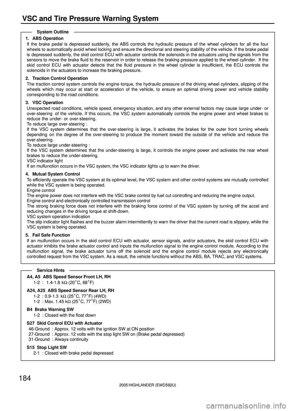
1. ABS Operation
If the brake pedal is depressed suddenly, the ABS controls the hydraulic pressure of the wheel cylinders for all the four
wheels to automatically avoid wheel locking and ensure the directional and steering stability of the vehicle. If the brake pedal
is depressed suddenly, the skid control ECU with actuator controls the solenoids in the actuators using the signals from the
sensors to move the brake fluid to the reservoir in order to release the braking pressure applied to the wheel cylinder. If the
skid control ECU with actuator detects that the fluid pressure in the wheel cylinder is insufficient, the ECU controls the
solenoids in the actuators to increase the braking pressure.
2. Traction Control Operation
The traction control system controls the engine torque, the hydraulic pressure of the driving wheel cylinders, slipping of the
wheels which may occur at start or acceleration of the vehicle, to ensure an optimal driving power and vehicle stability
corresponding to the road conditions.
3. VSC Operation
Unexpected road conditions, vehicle speed, emergency situation, and any other external factors may cause large under- or
over-steering of the vehicle. If this occurs, the VSC system automatically controls the engine power and wheel brakes to
reduce the under- or over-steering.
To reduce large over-steering :
If the VSC system determines that the over-steering is large, it activates the brakes for the outer front turning wheels
depending on the degree of the over-steering to produce the moment toward the outside of the vehicle and reduce the
over-steering.
To reduce large under-steering :
If the VSC system determines that the under-steering is large, it controls the engine power and activates the rear wheel
brakes to reduce the under-steering.
VSC indicator light
If an mulfunction occurs in the VSC system, the VSC indicator lights up to warn the driver.
4. Mutual System Control
To efficiently operate the VSC system at its optimal level, the VSC system and other control systems are mutually controlled
while the VSC system is being operated.
Engine control
The engine power does not interfere with the VSC brake control by fuel cut controlling and reducing the engine output.
Engine control and electronically controlled transmission control
The strong braking force does not interfere with the braking force control of the VSC system by turning off the accel and
reducing changes in the driving torque at shift-down.
VSC system operation indication
The slip indicator light flashes and the buzzer alarm intermittently to warn the driver that the current road is slippery, while the
VSC system is being operated.
5. Fail Safe Function
If an mulfunction occurs in the skid control ECU with actuator, sensor signals, and/or actuators, the skid control ECU with
actuator inhibits the brake actuator control and inputs the mulfunction signal to the engine control module. According to the
mulfunction signal, the brake actuator turns off the solenoid and the engine control module rejects any electronically
controlled request from the VSC system. As a result, the vehicle functions without the ABS, BA, TRAC, and VSC systems.
A4, A5 ABS Speed Sensor Front LH, RH
1-2 : 1.4-1.8 kW (20°C, 68°F)
A24, A25 ABS Speed Sensor Rear LH, RH
1-2 : 0.9-1.3 kW (25°C, 77°F) (4WD)
1-2 : Max. 1.45 kW (25°C, 77°F) (2WD)
B4 Brake Warning SW
1-2 : Closed with the float down
S27 Skid Control ECU with Actuator
46-Ground : Approx. 12 volts with the ignition SW at ON position
27-Ground : Approx. 12 volts with the stop light SW on (Brake pedal depressed)
31-Ground : Always continuity
S15 Stop Light SW
2-1 : Closed with brake pedal depressed
System Outline
Service Hints
Page 505 of 2572
2005 HIGHLANDER (EWD592U)
190
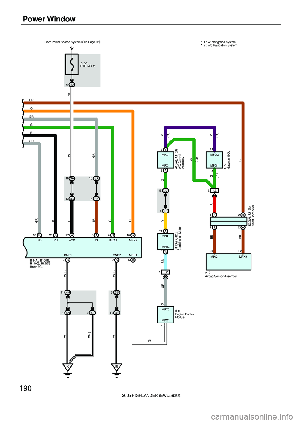
Power Window
GRB G GRO BR* 1 : w/ Navigation System
* 2 : w/o Navigation System
7. 5A
RAD NO. 2
1J 6
3A 10
3B 5 3A 8
3C 6
D 9 A 5 A 17 B 20 B21
GR
B
B
BR
GGRW
PD PU ACC IG BECU
A 2 D 7
IB 3B 3
3F 13 GND1 GND2
W- B W- B
IC 4H 11
4N 1
W- B W- B
4L 7
W- B
A 10
O
MPX2
B 6
IL2 1A 21
B 9
GR SB
MPX1B 2
A 9
YV
WMPX+
MPX-
MPX-
MPX+
MPX2
MPX1
W
3J 12
3E 1
G
MPD2
MPD1
IL2 12
B 1B2
A 1A2
A17MPX1 MPX2
G
GV R
BR BR
BR
11
4
(
*1)(
*1) (
*1)
G 5(
*2)
22 24
29
18E 6 From Power Source System (
See Page 62)
S30(
A)
, S31(
B) C11(
A)
, C12(
B)
A10(
A)
, A11(
B)
B 9(
A)
, B10(
B)
,
B11(
C)
, B12(
D)
A/C Control
Assembly
Airbag Sensor Assembly Body ECU
Combination Meter
Engine Control
Module
Gateway ECU
Shor t Connector