brake TOYOTA HIGHLANDER 2001 Service Manual PDF
[x] Cancel search | Manufacturer: TOYOTA, Model Year: 2001, Model line: HIGHLANDER, Model: TOYOTA HIGHLANDER 2001Pages: 2572, PDF Size: 34.8 MB
Page 412 of 2572
2005 HIGHLANDER (EWD592U)
11 5
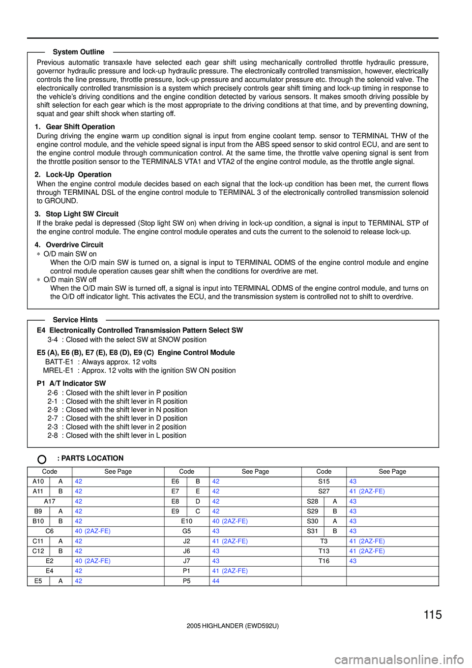
Previous automatic transaxle have selected each gear shift using mechanically controlled throttle hydraulic pressure,
governor hydraulic pressure and lock-up hydraulic pressure. The electronically controlled transmission, however, electrically
controls the line pressure, throttle pressure, lock-up pressure and accumulator pressure etc. through the solenoid valve. The
electronically controlled transmission is a system which precisely controls gear shift timing and lock-up timing in response to
the vehicle's driving conditions and the engine condition detected by various sensors. It makes smooth driving possible by
shift selection for each gear which is the most appropriate to the driving conditions at that time, and by preventing downing,
squat and gear shift shock when starting off.
1. Gear Shift Operation
During driving the engine warm up condition signal is input from engine coolant temp. sensor to TERMINAL THW of the
engine control module, and the vehicle speed signal is input from the ABS speed sensor to skid control ECU, and are sent to
the engine control module through communication control. At the same time, the throttle valve opening signal is sent from
the throttle position sensor to the TERMINALS VTA1 and VTA2 of the engine control module, as the throttle angle signal.
2. Lock-Up Operation
When the engine control module decides based on each signal that the lock-up condition has been met, the current flows
through TERMINAL DSL of the engine control module to TERMINAL 3 of the electronically controlled transmission solenoid
to GROUND.
3. Stop Light SW Circuit
If the brake pedal is depressed (Stop light SW on) when driving in lock-up condition, a signal is input to TERMINAL STP of
the engine control module. The engine control module operates and cuts the current to the solenoid to release lock-up.
4. Overdrive Circuit
*O/D main SW on
When the O/D main SW is turned on, a signal is input to TERMINAL ODMS of the engine control module and engine
control module operation causes gear shift when the conditions for overdrive are met.
*O/D main SW off
When the O/D main SW is turned off, a signal is input into TERMINAL ODMS of the engine control module, and turns on
the O/D off indicator light. This activates the ECU, and the transmission system is controlled not to shift to overdrive.
E4 Electronically Controlled Transmission Pattern Select SW
3-4 : Closed with the select SW at SNOW position
E5 (A), E6 (B), E7 (E), E8 (D), E9 (C) Engine Control Module
BATT-E1 : Always approx. 12 volts
MREL-E1 : Approx. 12 volts with the ignition SW ON position
P1 A/T Indicator SW
2-6 : Closed with the shift lever in P position
2-1 : Closed with the shift lever in R position
2-9 : Closed with the shift lever in N position
2-7 : Closed with the shift lever in D position
2-3 : Closed with the shift lever in 2 position
2-8 : Closed with the shift lever in L position
: PARTS LOCATION
CodeSee PageCodeSee PageCodeSee Page
A10A42E6B42S1543
A11B42E7E42S2741 (2AZ-FE)
A1742E8D42S28A43
B9A42E9C42S29B43
B10B42E1040 (2AZ-FE)S30A43
C640 (2AZ-FE)G543S31B43
C11A42J241 (2AZ-FE)T341 (2AZ-FE)
C12B42J643T1341 (2AZ-FE)
E240 (2AZ-FE)J743T1643
E442P141 (2AZ-FE)
E5A42P544
System Outline
Service Hints
Page 434 of 2572

2005 HIGHLANDER (EWD592U)
11 9
IF3 7
9IF3
B G BR
1 1
222
1 2
R- Y
B
2 2
15A H- LP
LH LWR
R- B
P
B 16
A 19IC3 7
1 2
EG A
H 2R- W W- B
EA AE10
B
H 4 J 1
W- B
J 3
B
L- R
52 3133
33 E10
IA
W- B
16 7813
OFF
Tail
Head
Low
High
Flash
Light
Control SW Dimmer SW
13 4A64F 4N2 B 14HU
B 15HF
B 17HEAD C 3
HRLYC 2
DRL
Y
O
LGR
BR- B
R- B
C13DRL NO. 2
Relay
D 14
R
P 3
PKB
4H 3
4M 9
B
IK3 4
P
IK3 16
WR- B
B
1
15A H- LP
RH LWR
7. 5A IG1
1K 10 1J62A4
7. 5A
RAD NO. 2
7. 5A ECU- B BR
53B 10 3A
GR
IG 5A
B
63C 83A
W
ACC 17 A
G
61H 10 1G
BR
BECU 9D 5IC3
W- L W- B
13 3F33BGN D2
W- B
2A
IBGND1
W- B
7D
4H 11
4N 14L7
IC
W- B
W- B
E 4
R- Y
R- Y
12 4H
LG
Y
Y
16
M 3
PKBIF3 4 From Power Sour ce System (
See Page 62)
B 9(
A)
, B10(
B)
,
B11(
C)
, B12(
D)
C11(
A)
, C12(
B)
Beam
Body ECU
Combination Meter
Combination SW
Headlight LH
(
Low Beam)
Headlight RH
(
Low Beam) Junction
Connector
Junction
Connector
Multi- Display Par king
Brake SW
Page 435 of 2572

2005 HIGHLANDER (EWD592U)
120
Headlight with Daytime Running Light
1. Daytime Running Light Operation
The headlight is turned on when all the following conditions are satisfied
*When the ignition switch is ON position
*When the generator is generating electricity
*When the light control SW is OFF position
*When the parking brake SW is OFF position
2. Headlight Operation
*The headlight comes on at the LOW position when the dimmer SW is turned to the low beam position with the light control
SW being HEAD position.
*If the dimmer SW is turned to the HIGH position with the light control SW being HEAD position, the headlight comes on at
the high beam position. Moreover, the high beam indicator light appears on the combination meter.
*Regardless of the light control SW positions, the headlight comes on at the low beam position when the dimmer SW is
turned to FLASH position. Moreover, the high beam indicator light appears on the combination meter.
B9 (A), B10 (B), B12 (D) Body ECU
(D) 7-Ground : Always continuity
(D)14-Ground : Continuity with parking brake pedal depressed
(B)17-Ground : Continuity with the light control SW at HEAD position
(A) 2-Ground : Always continuity
(A) 5-Ground : Approx. 12 volts with the ignition SW at ON position
: PARTS LOCATION
CodeSee PageCodeSee PageCodeSee Page
B9A42H138 (3MZ-FE)H440 (2AZ-FE)
B10B42H140 (2AZ-FE)J139 (3MZ-FE)
B11C42H238 (3MZ-FE)J141 (2AZ-FE)
B12D42H240 (2AZ-FE)J339 (3MZ-FE)
C11A42H338 (3MZ-FE)J341 (2AZ-FE)
C12B42H340 (2AZ-FE)M343
C1342H438 (3MZ-FE)P343
: RELAY BLOCKS
CodeSee PageRelay Blocks (Relay Block Location)
222Engine Room R/B (Engine Compartment Left)
323Engine Room R/B No.3 (Engine Compartment Rear Left)
System Outline
Service Hints
Page 448 of 2572

2005 HIGHLANDER (EWD592U)
133
S15 Stop Light SW
2-1 : Closed with the brake pedal depressed
: PARTS LOCATION
CodeSee PageCodeSee PageCodeSee Page
H1144J1444S1543
J1044R745
J1244R845
: JUNCTION BLOCK AND WIRE HARNESS CONNECTOR
CodeSee PageJunction Block and Wire Harness (Connector Location)
1E29Cowl Wire and Instrument Panel J/B (Lower Finish Panel)
4L32Cowl Wire and Passenger Side J/B (Right Side of Grove Box)
: CONNECTOR JOINING WIRE HARNESS AND WIRE HARNESS
CodeSee PageJoining Wire Harness and Wire Harness (Connector Location)
IA252Cowl Wire and Floor No.2 Wire (Left Kick Panel)
BG256Back Door No.1 Wire and Floor No.2 Wire (Rear Left of the Roof)
: GROUND POINTS
CodeSee PageGround Points Location
BC56Left Side of Rear Cross Member
BE56Left Side of Back Door
Service Hints
Page 468 of 2572

2005 HIGHLANDER (EWD592U)
153
T9 Towing Converter
3-Ground : Approx. 12 volts with the light control SW at TAIL or HEAD position
8-Ground : Always approx. 12 volts
5-Ground : Always continuity
9-Ground : Approx. 12 volts with the stop light SW on
S15 Stop Light SW
1-2 : Closed with the brake pedal depressed
: PARTS LOCATION
CodeSee PageCodeSee PageCodeSee Page
A1042J1244S1543
B942J1344T843
C1342J2043T945
J1044M343T1045
: JUNCTION BLOCK AND WIRE HARNESS CONNECTOR
CodeSee PageJunction Block and Wire Harness (Connector Location)
1D
1E29Cowl Wire and Instrument Panel J/B (Lower Finish Panel)
1H
()
2B27Engine Room Main Wire and Engine Room J/B (Engine Compartment Left)2F27Engine Room Main Wire and Engine Room J/B (Engine Compartment Left)
3B30Instrument Panel Wire and Center J/B (Behind the Instrument Panel Center)3E30Instrument Panel Wire and Center J/B (Behind the Instrument Panel Center)
4C
4E33
4GCowl Wire and Passenger Side J/B (Right Side of Grove Box)
4L32
g(g )
4M32
: CONNECTOR JOINING WIRE HARNESS AND WIRE HARNESS
CodeSee PageJoining Wire Harness and Wire Harness (Connector Location)
IA152Cowl Wire and Floor No 2 Wire (Left Kick Panel)IA252Cowl Wire and Floor No.2 Wire (Left Kick Panel)
IC252Engine Room Main Wire and Cowl Wire (Left Cowl Side Panel)IC352Engine Room Main Wire and Cowl Wire (Left Cowl Side Panel)
IL254Instrument Panel Wire and Cowl Wire (Upper Side of Passenger Side J/B)
: GROUND POINTS
CodeSee PageGround Points Location
IA52Left Cowl Side Panel
BC56Left Side of Rear Cross Member
: SPLICE POINTS
CodeSee PageWire Harness with Splice PointsCodeSee PageWire Harness with Splice Points
B956Floor No.2 Wire
Service Hints
Page 483 of 2572

2005 HIGHLANDER (EWD592U)
168
Cruise Control for 3MZ-FE
The cruise control system is a constant vehicle speed controller in which control of the switch on the instrument panel makes
it possible to automatically adjust the opening of the engine throttle valve without depressing of the accel pedal.
1. Set Operation
When the ON-OFF SW is turned on, the system starts preparations necessary for the cruise control and turns on the
indicator light in the combination meter.
2. Set Speed Control
When the - SET SW is operated with the ON-OFF SW turned on during travelling, the constant vehicle speed is controlled.
3. Coast Control
When the - SET SW is kept turned on during cruise control travelling, the engine control module controls the throttle valve to
decelerate the vehicle. Every time the - SET SW is turned on instantaneously, the vehicle speed is decelerated
approximately 1.5 km/h.
4. Accel Control
When the + RES SW is kept turned on during cruise control travelling, the engine control module controls the throttle valve to
accelerate the vehicle. Every time the + RES SW is turned on instantaneously, the vehicle speed is accelerated
approximately 1.5 km/h.
5. Resume Control
When the vehicle speed is within the low speed limit (Approximately 40 km/h, 25 mph) if the cruise control is cancelled, use
of the + RES SW accelerates the vehicle to the speed level used before canceling the cruise control.
6. Manual Cancel Mechanism
If any of the following signals is input during cruise control travelling, the cruise control is cancelled.
*The stop light SW is turned on.
*The CANCEL SW is turned on.
*The ON-OFF SW is turned off.
*Gear is shifted from D position to other positions than D.
7. Auto Cancel Function
If any of the following conditions is encountered, the cruise control is automatically cancelled.
*The stop light SW wiring is faulty or short-circuited.
*The vehicle speed signal is faulty.
*The electronically controlled throttle malfunctions.
8. Overdrive Control Function
The overdrive control may be cancelled if the vehicle travels on the slope during cruise control travelling. After the overdrive
control has been cancelled, when climbing hill is judged to finish from throttle opening information, the vehicle returns to the
overdrive control mode again after the overdrive return timer is completed.
E5 (A), E6 (B), E7 (E), E8 (D), E9 (C) Engine Control Module
(A) 9-Ground : Approx. 12 volts with ignition SW at ON or ST position
(A) 3, (B) 6-Ground : Always approx. 12 volts
(C) 1, (C) 7, (D) 6, (D) 7, (E) 6, (E) 7-Ground : Always continuity
(B)19-Ground : Approx. 12 volts with brake pedal depressed
(B)24-Ground : Continuity with ON-OFF SW at on in cruise control SW
Approx. 1540 W with CANCEL SW on in cruise control SW
Approx. 240 W with + RES SW on in cruise control SW
Approx. 630 W with - SET SW on in cruise control SW
C16 Combination SW
5-4 : Approx. 1540 W with CANCEL SW on
Approx. 240 W with + RES SW on
Approx. 630 W with - SET SW on
System Outline
Service Hints
Page 491 of 2572

2005 HIGHLANDER (EWD592U)
176
Cruise Control for 2AZ-FE
The cruise control system is a constant vehicle speed controller in which control of the switch on the instrument panel makes
it possible to automatically adjust the opening of the engine throttle valve without depressing of the accel pedal.
1. Set Operation
When the ON-OFF SW is turned on, the system starts preparations necessary for the cruise control and turns on the
indicator light in the combination meter.
2. Set Speed Control
When the - SET SW is operated with the ON-OFF SW turned on during travelling, the constant vehicle speed is controlled.
3. Coast Control
When the - SET SW is kept turned on during cruise control travelling, the engine control module controls the throttle valve to
decelerate the vehicle. Every time the - SET SW is turned on instantaneously, the vehicle speed is decelerated
approximately 1.5 km/h.
4. Accel Control
When the + RES SW is kept turned on during cruise control travelling, the engine control module controls the throttle valve to
accelerate the vehicle. Every time the + RES SW is turned on instantaneously, the vehicle speed is accelerated
approximately 1.5 km/h.
5. Resume Control
When the vehicle speed is within the low speed limit (Approximately 40 km/h, 25 mph) if the cruise control is cancelled, use
of the + RES SW accelerates the vehicle to the speed level used before canceling the cruise control.
6. Manual Cancel Mechanism
If any of the following signals is input during cruise control travelling, the cruise control is cancelled.
*The stop light SW is turned on.
*The CANCEL SW is turned on.
*The ON-OFF SW is turned off.
*Gear is shifted from D position to other positions than D.
7. Auto Cancel Function
If any of the following conditions is encountered, the cruise control is automatically cancelled.
*The stop light SW wiring is faulty or short-circuited.
*The vehicle speed signal is faulty.
*The electronically controlled throttle malfunctions.
8. Overdrive Control Function
The overdrive control may be cancelled if the vehicle travels on the slope during cruise control travelling. After the overdrive
control has been cancelled, when climbing hill is judged to finish from throttle opening information, the vehicle returns to the
overdrive control mode again after the overdrive return timer is completed.
E5 (A), E6 (B), E7 (E), E8 (D), E9 (C) Engine Control Module
(A) 9-Ground : Approx. 12 volts with ignition SW at ON or ST position
(A) 1, (B) 6-Ground : Always approx. 12 volts
(C) 1, (C) 7, (D) 6, (D) 7, (E) 6, (E) 7-Ground : Always continuity
(B)19-Ground : Approx. 12 volts with brake pedal depressed
(B)24-Ground : Continuity with ON-OFF SW at on in cruise control SW
Approx. 1540 W with CANCEL SW on in cruise control SW
Approx. 240 W with + RES SW on in cruise control SW
Approx. 630 W with - SET SW on in cruise control SW
C16 Combination SW
5-4 : Approx. 1540 W with CANCEL SW on
Approx. 240 W with + RES SW on
Approx. 630 W with - SET SW on
System Outline
Service Hints
Page 495 of 2572
2005 HIGHLANDER (EWD592U)
180
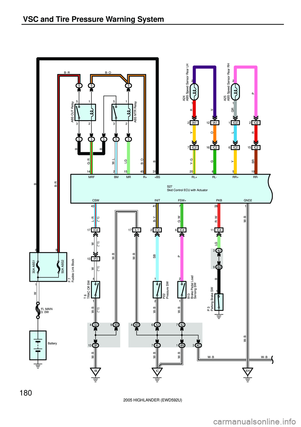
VSC and Tire Pressure Warning System
5
2 5
55IA1 IO2
MR 15 14
MRF1 2
IC2 6IC215
519 31
+BS RR+ RR-
1 2 FSW+
7
4J 3
4M 9
Y
R+ 45
B13
A25
28PKB
O
RL
1
S27
P 3ABS CUT RelayFL MAIN
3. 0W
Battery
WB
B- R
G- W
R- W B
GR
P Y
BRB B- OLG
B- R
2IO2
G- R
12 IA1
V RA24
RL- RL+6 2016 IC2 7IC22
1
Y- G
G
1 43CSW
41INIT
L- R
B- Y W W- B
W- B
IB
W- BT 6
4
121
P22
IC4 17 IC42
3J 44J6
ABS MTR Relay W- L
BM 25
1 89
50A ABS2 30A ABS1
5
5 5 51 51
32 32B- O
B
B
3F 13 4L74J 7
4N 1 4D 4 93G
IC
W- B
IL1 17 IC46
IF3 13
W
W- B
SB
P W- B
W- B W- B
IC4 11
LG
EH
W- B
1 GN D2
W- BF 7
(
*1) (
*1) (
*1) (
*1)
W- B 4C 3
W- B
ABS Speed Sensor Rear LH
ABS Speed Sensor Rear RH Br ake Pedal Load
Sensing SWFusible Link Block
Parking Brake SWPr essure SW
Skid Control ECU with Actuator
TRAC Off SW
Page 498 of 2572

2005 HIGHLANDER (EWD592U)
183
10A
IGN
1G 6
V
SB
SB
BR
ABS VSC
Brake
W- BB 7A17 B11 B10 LG4M 4
4E 1
J 6
E
E
P SB
SB
6IF3 IF3 6IF2
R
IF3 16 15
V
R- B W- B VB WP
B 4P
W SB
IL1 9
A 13
IC4 1IF318
GR BR
6B
IB A 12 A 2A
5V 7V
Speedometer
1
B 6
R
11 A
3B 12
3K 2 11 IL2
IK3 12 V
VR
32A 10A
DOME
LG V
33D 93F
LG
PB
73C 43A 13 1KFrom Power Source System (
See Page 62)
10A
HEATER
BR
B 6
6B
(
2WD)(
2WD) TRAC OFFSlip Tire Air
Pressure
64H 11 4D
C11(
A)
, C12(
B)
Brake Warning SW
Combination Meter
Junction
Connector
2 1
Page 499 of 2572
2005 HIGHLANDER (EWD592U)
184
VSC and Tire Pressure Warning System
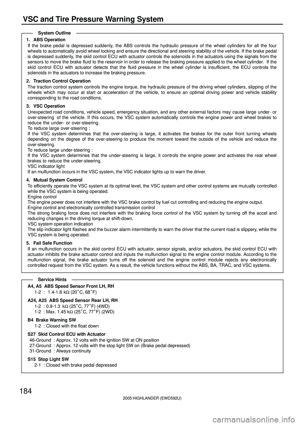
1. ABS Operation
If the brake pedal is depressed suddenly, the ABS controls the hydraulic pressure of the wheel cylinders for all the four
wheels to automatically avoid wheel locking and ensure the directional and steering stability of the vehicle. If the brake pedal
is depressed suddenly, the skid control ECU with actuator controls the solenoids in the actuators using the signals from the
sensors to move the brake fluid to the reservoir in order to release the braking pressure applied to the wheel cylinder. If the
skid control ECU with actuator detects that the fluid pressure in the wheel cylinder is insufficient, the ECU controls the
solenoids in the actuators to increase the braking pressure.
2. Traction Control Operation
The traction control system controls the engine torque, the hydraulic pressure of the driving wheel cylinders, slipping of the
wheels which may occur at start or acceleration of the vehicle, to ensure an optimal driving power and vehicle stability
corresponding to the road conditions.
3. VSC Operation
Unexpected road conditions, vehicle speed, emergency situation, and any other external factors may cause large under- or
over-steering of the vehicle. If this occurs, the VSC system automatically controls the engine power and wheel brakes to
reduce the under- or over-steering.
To reduce large over-steering :
If the VSC system determines that the over-steering is large, it activates the brakes for the outer front turning wheels
depending on the degree of the over-steering to produce the moment toward the outside of the vehicle and reduce the
over-steering.
To reduce large under-steering :
If the VSC system determines that the under-steering is large, it controls the engine power and activates the rear wheel
brakes to reduce the under-steering.
VSC indicator light
If an mulfunction occurs in the VSC system, the VSC indicator lights up to warn the driver.
4. Mutual System Control
To efficiently operate the VSC system at its optimal level, the VSC system and other control systems are mutually controlled
while the VSC system is being operated.
Engine control
The engine power does not interfere with the VSC brake control by fuel cut controlling and reducing the engine output.
Engine control and electronically controlled transmission control
The strong braking force does not interfere with the braking force control of the VSC system by turning off the accel and
reducing changes in the driving torque at shift-down.
VSC system operation indication
The slip indicator light flashes and the buzzer alarm intermittently to warn the driver that the current road is slippery, while the
VSC system is being operated.
5. Fail Safe Function
If an mulfunction occurs in the skid control ECU with actuator, sensor signals, and/or actuators, the skid control ECU with
actuator inhibits the brake actuator control and inputs the mulfunction signal to the engine control module. According to the
mulfunction signal, the brake actuator turns off the solenoid and the engine control module rejects any electronically
controlled request from the VSC system. As a result, the vehicle functions without the ABS, BA, TRAC, and VSC systems.
A4, A5 ABS Speed Sensor Front LH, RH
1-2 : 1.4-1.8 kW (20°C, 68°F)
A24, A25 ABS Speed Sensor Rear LH, RH
1-2 : 0.9-1.3 kW (25°C, 77°F) (4WD)
1-2 : Max. 1.45 kW (25°C, 77°F) (2WD)
B4 Brake Warning SW
1-2 : Closed with the float down
S27 Skid Control ECU with Actuator
46-Ground : Approx. 12 volts with the ignition SW at ON position
27-Ground : Approx. 12 volts with the stop light SW on (Brake pedal depressed)
31-Ground : Always continuity
S15 Stop Light SW
2-1 : Closed with brake pedal depressed
System Outline
Service Hints