key TOYOTA HIGHLANDER 2009 XU40 / 2.G Manual Online
[x] Cancel search | Manufacturer: TOYOTA, Model Year: 2009, Model line: HIGHLANDER, Model: TOYOTA HIGHLANDER 2009 XU40 / 2.GPages: 608, PDF Size: 11.73 MB
Page 450 of 608
450 4-3. Do-it-yourself maintenance
■Before recharging
When recharging, the battery produces hydrogen gas which is flammable
and explosive. Therefore, before recharging:
●If recharging with the battery installed on the vehicle, be sure to discon-
nect the ground cable.
● Make sure the power switch on the charger is off when connecting and
disconnecting the charger cables to the battery.
■ After recharging the battery (vehicles with smart key system)
The engine may not start. Follow the procedure below to initialize the sys-
tem.
Shift the shift lever to P.
Open and close any of the doors.
Restart the engine.
CAUTION
■Chemicals in the battery
A battery contains poisonous and corrosive sulfuric acid and may produce
hydrogen gas which is flammable and explosive. To reduce the risk of death
or serious injury, take the following precautions while working on or near bat-
tery:
●Do not cause sparks by touching the battery terminals with tools.
● Do not smoke or light a match near the battery.
● Avoid contact with eyes, skin and clothes.
● Never inhale or swallow electrolyte.
● Wear protective safety glasses when working near the battery.
● Keep children away from the battery.
■ Where to safety charge the battery
Always charge the battery in an open area. Do not charge the battery in a
garage or closed room where there is not sufficient ventilation.
STEP1
STEP2
STEP3
Page 455 of 608
455
4-3. Do-it-yourself maintenance
4
Maintenance and care
Installing tire pressure warning valves and transmitters
When replacing tires or wheels, tire pressure warning valves and
transmitters must also be installed.
When new tire pressure warning valves and transmitters are
installed, new tire pressure warning valve and transmitter ID codes
must be registered in the tire pre ssure warning computer and the tire
pressure warning system must be initialized. Have tire pressure
warning valve and transmitter ID codes registered by your Toyota
dealer. ( →P. 457)
Initializing the tire pressure warning system
■ The tire pressure warning system must be initialized when the
tire inflation pressure is changed (such as when changing
traveling speed or towing a trailer.)
When the tire pressure warning syst em is initialized, the current tire
inflation pressure is set as the benchmark pressure.
■ How to initialize the tire pressure warning system
Park the vehicle in safe place and turn the “ENGINE START
STOP” switch or the engine switch OFF.
While the vehicle is moving, in itialization is not performed.
Adjust the tire inflation pressure to the specified cold tire infla-
tion pressure level. ( →P. 562)
Make sure to adjust the tire pressure to the specified cold tire
inflation pressure level. The tire pressure warning system will
operate based on this pressure level.
Turn the “ENGINE START STOP” switch to IGNITION ON
mode (vehicles with smart key sy stem) or the engine switch to
the “ON” position (vehicles without smart key system).
STEP1
STEP2
STEP3
Page 456 of 608
456 4-3. Do-it-yourself maintenance
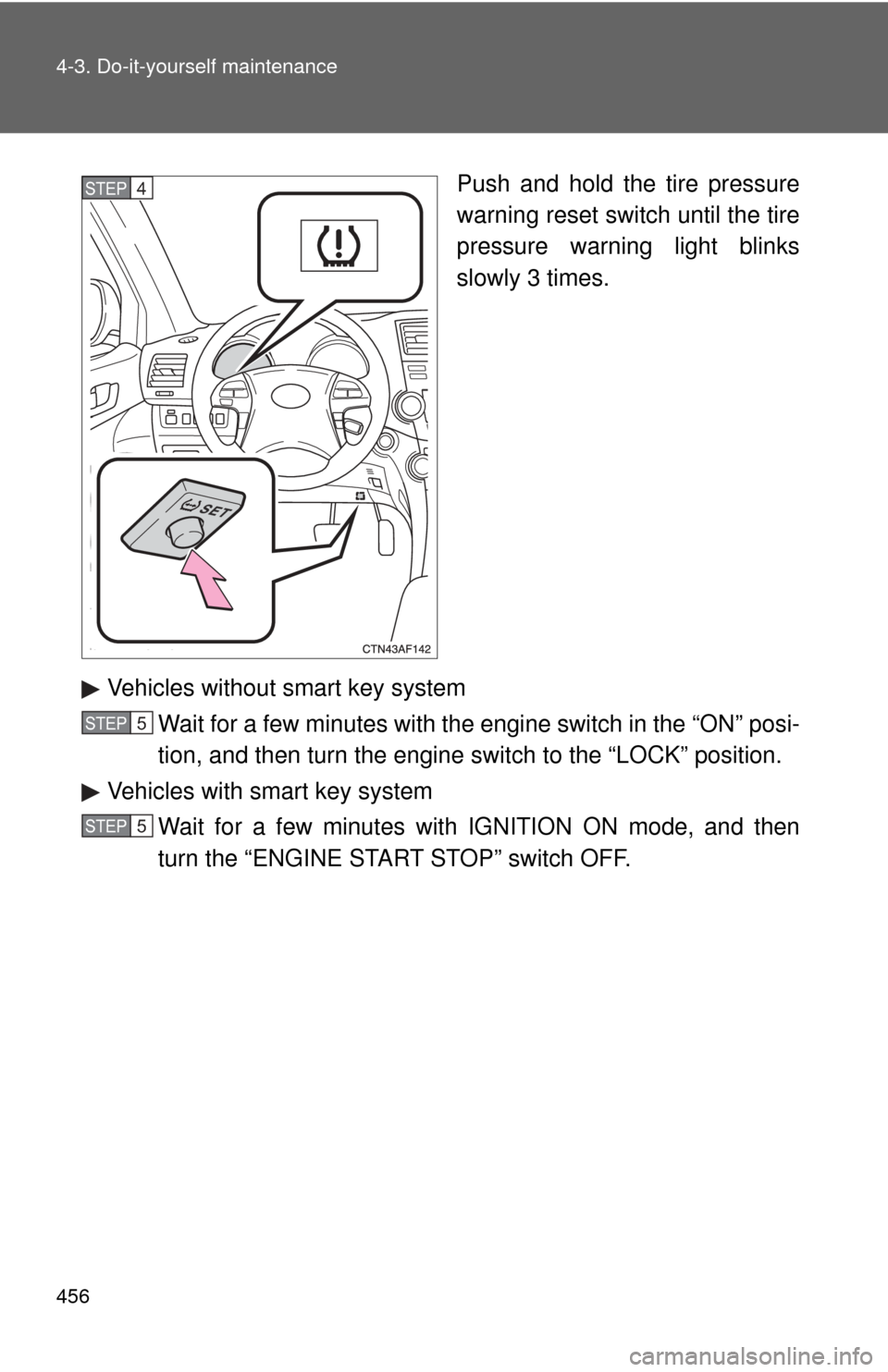
Push and hold the tire pressure
warning reset switch until the tire
pressure warning light blinks
slowly 3 times.
Vehicles without smart key system Wait for a few minutes with the engine switch in the “ON” posi-
tion, and then turn the engine switch to the “LOCK” position.
Vehicles with smart key system Wait for a few minutes with IGNITION ON mode, and then
turn the “ENGINE START STOP” switch OFF.STEP4
STEP5
STEP5
Page 469 of 608
469
4-3. Do-it-yourself maintenance
4
Maintenance and care
Air conditioning filter
The air conditioning filter must be changed regularly to maintain air
conditioning efficiency.
■ Removal method
Vehicles without smart key sy stem: Turn the engine switch
OFF.
Vehicles with smart key system: Turn the “ENGINE START
STOP” switch OFF.
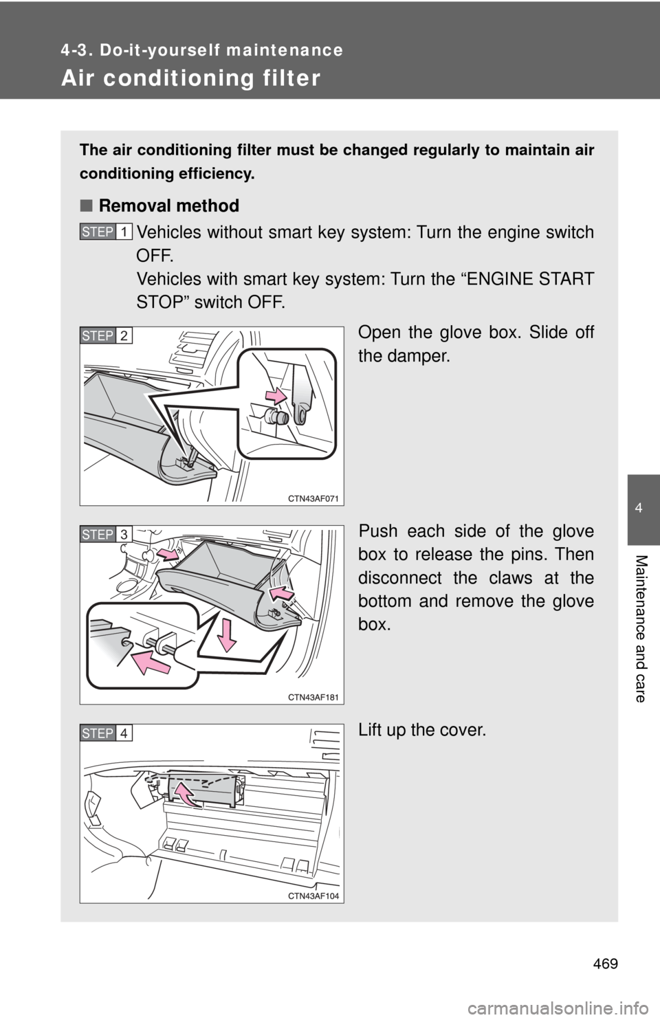
Open the glove box. Slide off
the damper.
Push each side of the glove
box to release the pins. Then
disconnect the claws at the
bottom and remove the glove
box.
Lift up the cover.
STEP1
STEP2
STEP3
STEP4
Page 472 of 608
472
4-3. Do-it-yourself maintenance
Wireless remote control/electronic key battery
Replace the battery with a new one if it is discharged.
■You will need the following items:
●Flathead screwdriver (To prevent damage to the key, cover
the tip of the screwdriver with a rag.)
● Small Phillips-head screwdriver
● Lithium battery CR2032 (vehicles without smart key system),
CR1632 (vehicles with smart key system)
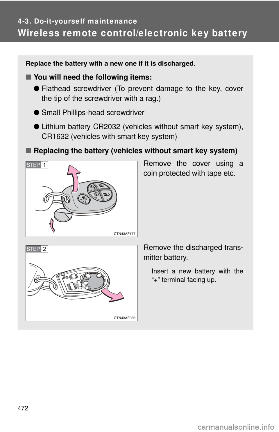
■ Replacing the battery (vehicles without smart key system)
Remove the cover using a
coin protected with tape etc.
Remove the discharged trans-
mitter battery.
Insert a new battery with the
“+” terminal facing up.
STEP1
STEP2
Page 473 of 608
473
4-3. Do-it-yourself maintenance
4
Maintenance and care
■
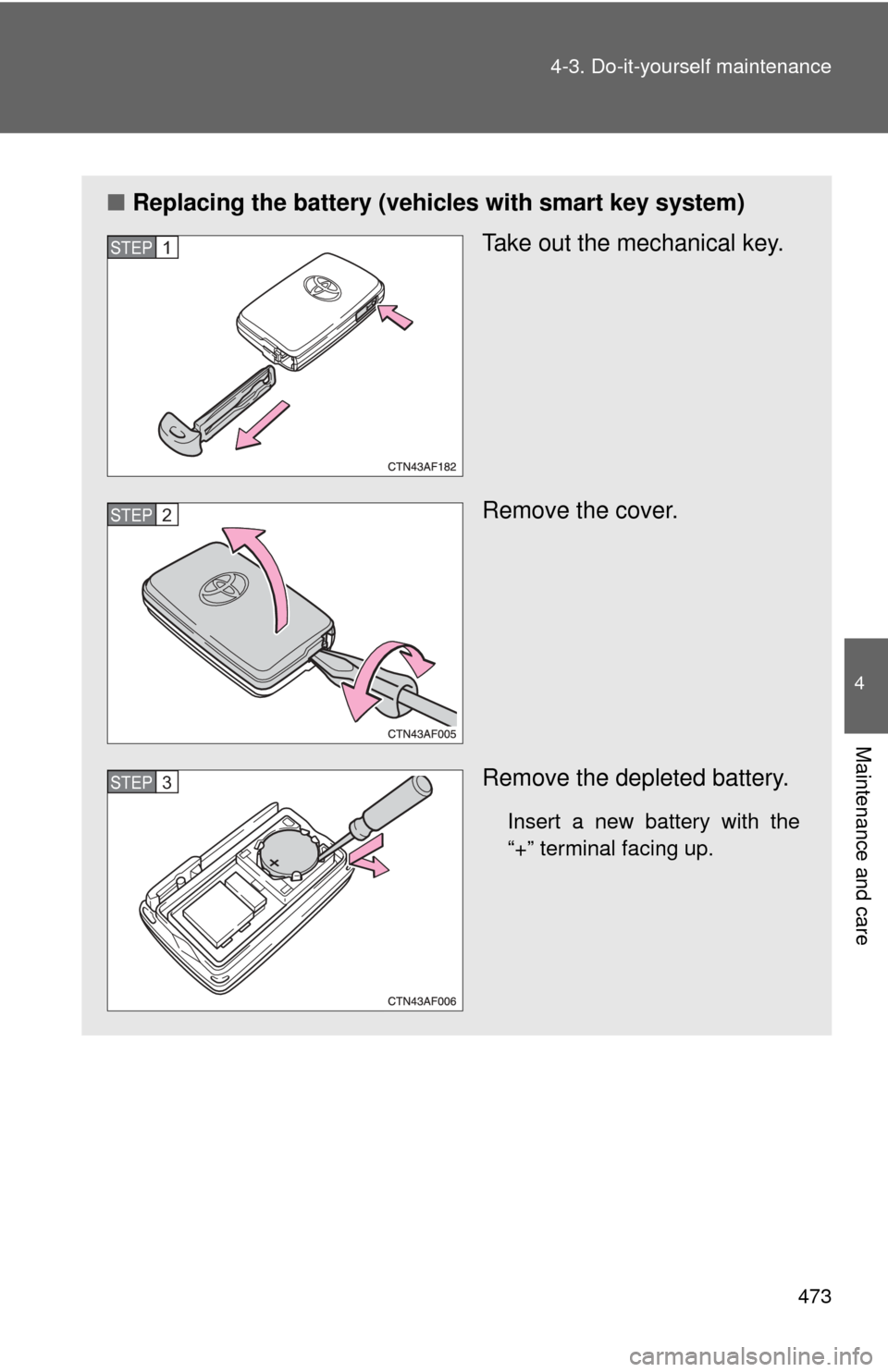
Replacing the battery (vehicles with smart key system)
Take out the mechanical key.
Remove the cover.
Remove the depleted battery.
Insert a new battery with the
“+” terminal facing up.
STEP1
STEP2
STEP3
Page 474 of 608
474 4-3. Do-it-yourself maintenance
■If the electronic key battery is discharged
The following symptoms may occur.
●The smart key system and wireless remote control will not function prop-
erly.
● The operational range is reduced.
■ Use a CR2032 (vehicles without sm art key system) or CR1632 (vehicles
with smart key system) lithium battery
● Batteries can be purchased at your Toyota dealer, jewelers, or camera
stores.
● Replace only with the same or equivalent type recommended by your
Toyota dealer.
● Dispose of used batteries according to the local laws.
CAUTION
■Removed battery and other parts
Keep away from children.
These parts are small and if swallowed by a child they can cause choking.
NOTICE
■For normal operation after replacing the battery
Observe the following precautions to prevent accidents.
●Always work with dry hands.
Moisture may cause the battery to rust.
● Do not touch or move any other components inside the remote control.
● Do not bend either of the battery terminals.
Page 475 of 608
475
4-3. Do-it-yourself maintenance
4
Maintenance and care
Checking and replacing fuses
If any of the electrical components do not operate, a fuse may have
blown. If this happens, check and replace the fuses as necessary.
Vehicles without smart key system: Turn the engine switch
OFF.
Vehicles with smart key system: Turn the “ENGINE START
STOP” switch OFF.
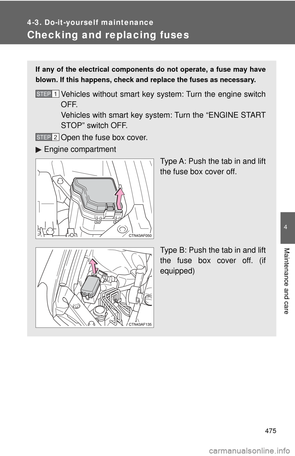
Open the fuse box cover.
Engine compartment Type A: Push the tab in and lift
the fuse box cover off.
Type B: Push the tab in and lift
the fuse box cover off. (if
equipped)STEP1
STEP2
Page 480 of 608

480 4-3. Do-it-yourself maintenance
25 CRT10 A Rear seat entertainment system
26 RADIO1 15 A Audio system
27 ECU-B 10 ASteering sensor, gauges and
meters, clock, air conditioning sys-
tem, main body ECU, wireless
remote control, smart key system,
power back door, on-board diagno-
sis system
28 DOME 10 AVanity lights, personal lights, inte-
rior light, gauges and meters,
engine switch light, door courtesy
lights, power back door
29 AMP 15 A Audio system
30 TOWING 30 A Trailer lights
31 IG2 25 A INJ NO.1, INJ NO.2
32 STR LOCK 20 A Steering lock system
33 EFI MAIN 25 A EFI NO.2, EFI NO.3
34 HAZ 15 A Turn signal lights
35 G/H 10 APower door lock system, multiplex
communication system
36 ALT-S 7.5 A Charging system
37 AM2 7.5 A Multiplex communication system
38 H-LP LH 15 A Left-hand headlight (high beam)
39 H-LP RH 15 A Right-hand headlight (high beam)
40 H-LP LL 15 A Left-hand headlight (low beam)
41 H-LP RL 15 A Right-hand headlight (low beam)
42 HORN 10 A Horn
43 EFI NO.1 10 AMultiport fuel injection system/
sequential multiport fuel injection
system, smart key system
FuseAmpereCircuit
Page 484 of 608

484 4-3. Do-it-yourself maintenance
22 GAUGE NO.1 10 AAudio system, outside rear view
mirror defoggers, back-up lights,
charging system, emergency flash-
ers, traction control system, instru-
ment panel light control dial,
windshield wiper deicer
23 FR WIP 30 A Windshield wipers and washer
24 RR WIP 15 A Rear window wiper and washer
25 IGN 10 A Multiport fuel injection system/
sequential multiport fuel injection
system, steering lock system, anti-
lock brake system, smart key sys-
tem, SRS airbag system
26 GAUGE NO.2 7.5 A Gauges and meters, rear view
monitor
27 ECU-ACC 7.5 A Auto anti-glare rear view mirrors,
shift lock system, smart key system
28 ACC SOCK
NO.1 10 A Power outlet
29 ACC SOCK
NO.2 20 A Power outlet
30 RADIO NO.2 7.5 A Audio system, clock, rear seat
entertainment system, charging
system, interior lights, personal
lights
31 MIR HTR 15 A Outside rear view mirror defoggers
FuseAmpereCircuit