warning light TOYOTA HIGHLANDER 2022 Repair Manual
[x] Cancel search | Manufacturer: TOYOTA, Model Year: 2022, Model line: HIGHLANDER, Model: TOYOTA HIGHLANDER 2022Pages: 568, PDF Size: 13.73 MB
Page 249 of 568
2494-5. Using the driving support systems
4
Driving
WARNING
●The vehicle is driven in an area
without white (yellow) lines,
such as in front of a tollgate or
checkpoint, or at an intersec-
tion, etc.
●The white (yellow) lines are
cracked, “Botts’ dots”, “Raised
pavement marker” or stones are
present.
●The white (yellow) lines cannot
be seen or are difficult to see
due to sand, etc.
●The vehicle is driven on a road
surface that is wet due to rain,
puddles, etc.
●The traffic li nes are yellow
(which may be more difficult to
recognize than lines that are
white).
●The white (yellow) lines cross
over a curb, etc.
●The vehicle is driven on a bright
surface, such as concrete.
●If the edge of the road is not
clear or straight.
●The vehicle is driven on a sur-
face that is bright due to
reflected light, etc.
●The vehicle is driven in an area
where the brightness changes
suddenly, such as at the
entrances and exits of tunnels,
etc.
●Light from the h eadlights of an
oncoming vehicle, the sun, etc.
enters the camera.
●The vehicle is driven on a slope.
●The vehicle is driven on a road
which tilts left or right, or a wind-
ing road.
●The vehicle is driven on an
unpaved or rough road.
●The traffic lane is excessively
narrow or wide.
●The vehicle is extremely tilted
due to carrying heavy luggage
or having improper tire pres-
sure.
●The distance to the preceding
vehicle is extremely short.
●The vehicle is moving up and
down a large amount due to
road conditions during driving
(poor roads or road seams).
●When driving in a tunnel or at
night with the headlights off or
when a headlight is dim due to
its lens being dir ty or it being
misaligned.
●The vehicle is struck by a cross-
wind.
●The vehicle is affected by wind
from a vehicle driven in a
nearby lane.
●The vehicle has just changed
lanes or crossed an intersec-
tion.
●Tires which differ by structure,
manufacturer, brand or tread
pattern are used.
●When tires of a size other than
specified are installed.
●Snow tires, etc . are equipped.
●The vehicle is b eing driven at
extremely high speeds.
Page 260 of 568
2604-5. Using the driving support systems
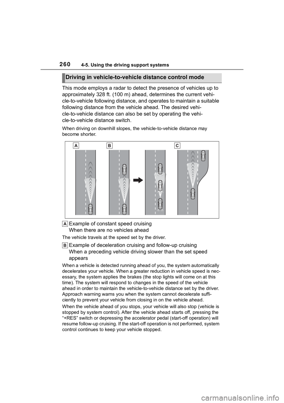
This mode employs a radar to detect the presence of vehicles up to
approximately 328 ft. (100 m) ahead, determines the current vehi-
cle-to-vehicle following distance, and operates to maintain a s uitable
following distance from the vehicle ahead. The desired vehi-
cle-to-vehicle distance can also be set by operating the vehi-
cle-to-vehicle distance switch.
When driving on downhill slopes, t he vehicle-to-vehicle distance may
become shorter.
Example of constant speed cruising
When there are no vehicles ahead
The vehicle travels at the speed set by the driver.
Example of deceleration crui sing and follow-up cruising
When a preceding vehicle driving slower than the set speed
appears
When a vehicle is detected runni ng ahead of you, the system automatically
decelerates your vehicle. When a greater reduction in vehicle s peed is nec-
essary, the system applies the brakes (the stop lights will come on at this
time). The system will respond to changes in the speed of the vehicle
ahead in order to maintain the vehicle-to-vehicle distance set by the driver.
Approach warning warns you when the system cannot decelerate suffi-
ciently to prevent your vehicle from closing in on the vehicle ahead.
When the vehicle ahead of you st ops, your vehicle will also stop (vehicle is
stopped by system control). Afte r the vehicle ahead starts off, pressing the
“+RES” switch or depressing the accelerator pedal (start-off operation) will
resume follow-up cruising. If the start-off operation is not pe rformed, system
control continues to keep your vehicle stopped.
Driving in vehicle-to-vehicle distance control mode
Page 277 of 568
2774-5. Using the driving support systems
4
Driving
reduce battery consumption. To
prevent the audio system from
being cut off, keep the volume of
audio system at a moderate level.
If the audio system has been cut
off, turn the engine switch off, wait
for 3 seconds or more and then
turn it to ACC or ON to re-enable
the audio system.
●The audio system may not be acti-
vated if the battery terminals are
disconnected and then recon-
nected. If this o ccurs, turn the
engine switch off and then repeat
the following operation twice to
activate the audio system nor-
mally.
• Turn the engine s witch to ON and
then to OFF.
■Replacing the battery
P. 4 9 2
■If the Stop & Start cancel indica-
tor flashes continuously
The system may be malfunctioning.
Have the vehicle inspected by your
Toyota dealer.
■If “Stop & Start System Mal-
function Visit Your Dealer” is
displayed on the multi-informa-
tion display
The system may be malfunctioning.
Have the vehicle inspected by your
Toyota dealer.
WARNING
■When the Stop & Start system
is operating
Make sure to dis able the Stop &
Start system while the vehicle is in
a poorly ventilated area. If not dis-
abled, the engine may be auto-
matically restarted unexpectedly,
causing exhaust gases to collect
and enter the vehicle, possibly
resulting in death or a serious
health hazard.
●Do not leave the vehicle while
the engine is stopped by the
Stop & Start system (while the
Stop & Start indicator is on). An
accident may occur due to the
automatic engine start function.
●Depress the brake pedal and
apply the parking brake when
necessary while the engine is
stopped by the Stop & Start sys-
tem (while the Stop & Start indi-
cator is on).
NOTICE
■To ensure the system oper-
ates correctly
If any of the follo wing situations
occur, the Stop & Start system
may not operate correctly. Have
your vehicle inspected by your
Toyota dealer.
●While the driver’s seat belt is
fastened, the driver’s and front
passenger’s seat belt reminder
light flashes.
●Even though the driver’s seat
belt is not fastened, the driver’s
and front passenger’s seat belt
reminder light does not illumi-
nate.
●Even though the driver’s door is
closed, the open door warning
light is illuminated or the interior
light is illumina ted when the
interior light switch is in the door
position.
●Even though the driver’s door is
open, the open door warning
light does not illu minate or the
interior light doe s not illuminate
when the interior light switch is
in the door position.
Page 278 of 568

2784-5. Using the driving support systems
*: If equipped
Meter control switches
Turning the Blind Spot Monitor
on/off.
When the BSM function is disabled,
the BSM OFF indicator illuminates.
Outside rear view mirror indi-
cators
When a vehicle is detected in a
blind spot of the outside rear view
mirrors or approaching rapidly from
behind into a blind spot, the outside
rear view mirror indicator on the
detected side will illuminate. If the
turn signal lever is operated toward
the detected side, the outside rear
view mirror indicator flashes.
■Outside rear view mirror indica-
tor visibility
In strong sunlight, the outside rear
view mirror indicator may be difficult
to see.
■When “Blind Spot Monitor
Unavailable” is shown on the
multi-information display
Ice, snow, mud, etc., may be
attached to the rear bumper around
the sensors. ( P.280) The system
should return to normal operation
after removing the ice, snow, mud,
etc. from the rear bumper. Addition-
ally, the sensors may not operate
normally when drivin g in extremely
BSM (Blind Spot Moni-
tor)*
The Blind Spot Monitor is a
system that uses rear side
radar sensors installed on
the inner side of the rear
bumper on the left and right
side to assist the driver in
confirming safety when
changing lanes.
WARNING
■Cautions regarding the use of
the system
The driver is solely responsible for
safe driving. Always drive safely,
taking care to o bserve your sur-
roundings.
The Blind Spot Monitor is a sup-
plementary function which alerts
the driver that a v ehicle is in a
blind spot of the outside rear view
mirrors or is approaching rapidly
from behind into a blind spot. Do
not overly rely on the Blind Spot
Monitor. As the function cannot
judge if it is safe to change lanes,
over reliance could lead to an
accident resulting in death or seri-
ous injury.
As the system may not function
correctly under certain condi-
tions, the driver’s own visual con-
firmation of safety is necessary.
System components
Page 281 of 568
2814-5. Using the driving support systems
4
Driving
Use the meter control switches
to turn on/off the function.
4.2-inch display
1 Press or of the meter
control switches and select
.
2 Press or of the meter
control switches to select
and then press .
7-inch display
1 Press or of the meter
control switches and select
.
2 Press or of the meter
control switches to select
and then press .
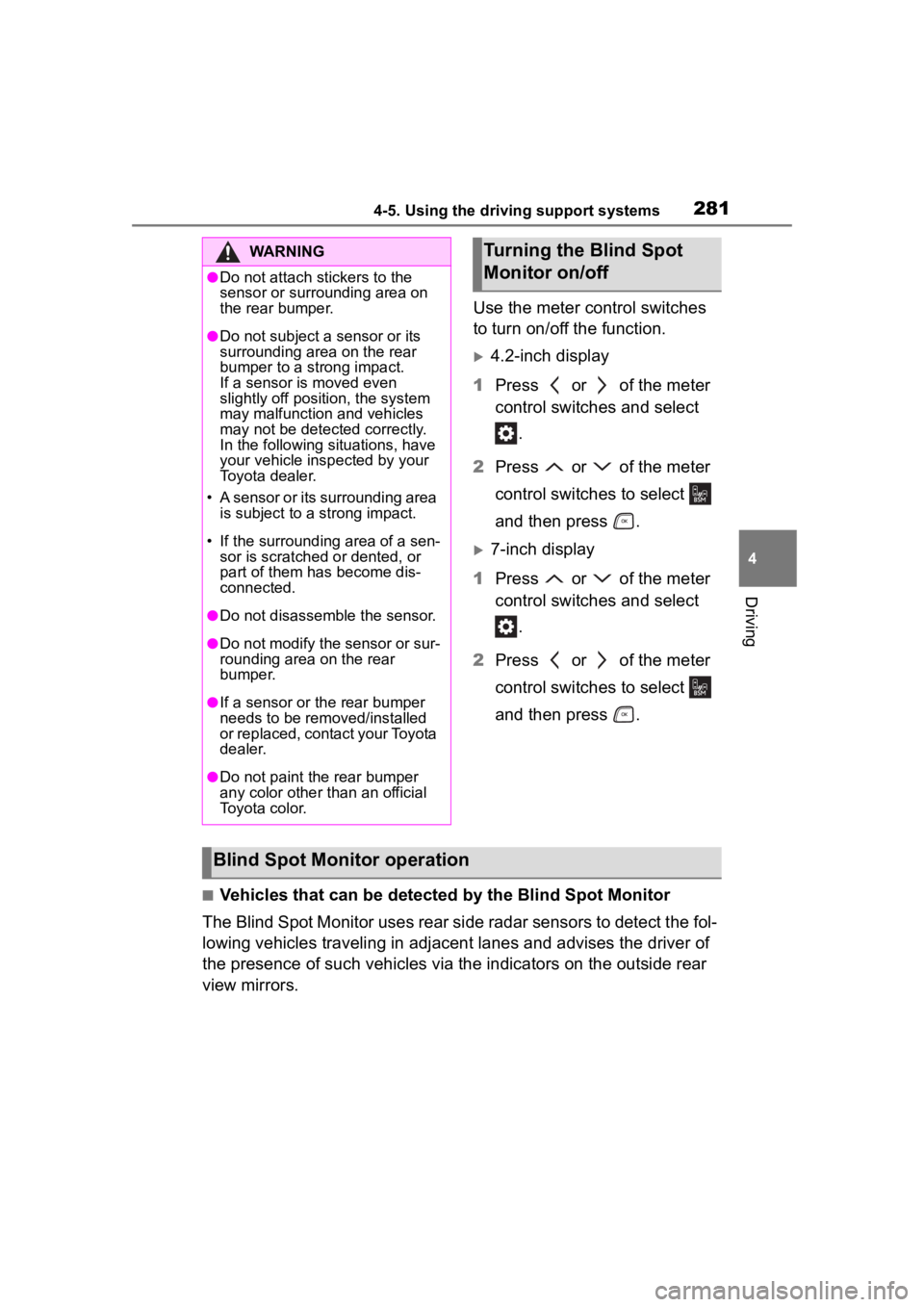
■Vehicles that can be detected by the Blind Spot Monitor
The Blind Spot Monitor uses rear side radar sensors to detect the fol-
lowing vehicles traveling in adjacent lanes and advises the driver of
the presence of such vehicles via the indicators on the outside rear
view mirrors.
WARNING
●Do not attach stickers to the
sensor or surrounding area on
the rear bumper.
●Do not subject a sensor or its
surrounding area on the rear
bumper to a strong impact.
If a sensor is moved even
slightly off position, the system
may malfunction and vehicles
may not be detected correctly.
In the following si tuations, have
your vehicle inspected by your
Toyota dealer.
• A sensor or its surrounding area is subject to a strong impact.
• If the surrounding area of a sen- sor is scratched or dented, or
part of them has become dis-
connected.
●Do not disassemble the sensor.
●Do not modify the sensor or sur-
rounding area on the rear
bumper.
●If a sensor or th e rear bumper
needs to be removed/installed
or replaced, contact your Toyota
dealer.
●Do not paint the rear bumper
any color other than an official
Toyota color.
Turning the Blind Spot
Monitor on/off
Blind Spot Monitor operation
Page 286 of 568
2864-5. Using the driving support systems
■The system can be operated
when
●The engine switch is in ON.
●Intuitive parking assist function is
on.
●The vehicle speed is less than
about 6 mph (10 km/h).
●A shift lever other than P.
■If “Parking Assist Unavailable”
is displayed on the multi-infor-
mation display
●Water may be continuously flow-
ing over the sensor surface, such
as in a heavy rain. When the sys-
tem determines that it is normal,
the system will return to normal.
WARNING
■Cautions regarding the use of
the system
There is a limit to the degree of
recognition accuracy and control
performance that this system can
provide, do not ov erly rely on this
system. The driver is always
responsible for paying attention to
the vehicle’ surroundings and
driving safely.
■To ensure the system can
operate properly
Observe the following precau-
tions.
Failing to do so may result in the
vehicle being unable to be driven
safely and possibly cause an acci-
dent.
●Do not damage the sensors,
and always keep them clean.
●Do not attach a sticker or install
an electronic component, such
as a backlit license plate (espe-
cially fluorescent type), fog
lights, fender pole or wireless
antenna near a radar sensor.
●Do not subject the surrounding
area of the sensor to a strong
impact. If subjected to an
impact, have the vehicle
inspected by your Toyota
dealer. If the fr ont or rear
bumper needs to be
emoved/installed or replaced,
contact your Toyota dealer.
●Do not modify, disassemble or
paint the sensors.
●Do not attach a license plate
cover.
●Keep your tires properly
inflated.
■When to disable the function
In the following situations, disable
the function as it may operate
even though there is no possibility
of a collision.
●Failing to observe the warnings
above.
●A non-genuine Toyota suspen-
sion (lowered suspension, etc.)
is installed.
■Notes when washing the vehi-
cle
Do not apply intensive bursts of
water or steam to the sensor
area.
Doing so may result in the sensor
malfunctioning.
●When using a high pressure
washer to wash the vehicle, do
not spray the sensors directly,
as doing so may cause a sensor
to malfunction.
●When using steam to clean the
vehicle, do not direct steam too
close to the sensors as doing so
may cause a sensor to malfunc-
tion.
Page 294 of 568
2944-5. Using the driving support systems
right or left at the rear of the vehicle
is detected, a buzzer will sound.
4.2-inch display
Use the meter control switches
to enable/disable the RCTA
function. ( P.89)
1 Press or to select .
2 Press or to select
“RCTA” and then press .
7-inch display
Use the meter control switches
to enable/disable the RCTA
function. ( P.98)
1 Press or to select .
2 Press or to select
“RCTA” and then press .
When the RCTA function is dis-
abled, the RCTA OFF indicator
( P.78) illuminates on the
multi-information display. (Each
time the engine switch is turned off
then changed to ON, the RCTA
function will be enabled automati-
cally.)■Outside rear vie w mirror indica-
tor visibility
In strong sunlight, the outside rear
view mirror indicator may be difficult
to see.
■Hearing the RCTA buzzer
The RCTA buzzer may be difficult to
hear over loud noises, such as if the
audio system volume is high.
■When “Rear Cross Traffic Alert
Unavailable” is shown on the
multi-information display
Water, ice, snow, mud, etc., may be
attached to the rear bumper around
the sensors. ( P.280) Removing
the water, ice, snow, mud, etc., from
the attached to the rear bumper
around the sensors to return the
function to normal.
Additionally, the function may not
Turning the RCTA func-
tion on/off
WARNING
■Cautions regarding the use of
the function
The driver is solely responsible for
safe driving. Always drive safely,
taking care to observe your sur-
roundings.
The RCTA function is only a sup-
plementary function which alerts
the driver that a vehicle is
approaching from the right or left
at the rear of the vehicle. As the
RCTA function may not function
correctly under certain condi-
tions, the driver’s own visual con-
firmation of safety is necessary.
Over reliance on this function may
lead to an accident resulting
death or serious injury.
NOTICE
■Before using the RCTA func-
tion
Do not place objects near the sen-
sors.
Page 313 of 568
3134-5. Using the driving support systems
4
Driving
Control that is suitable for the
following road conditions can be
performed by switching to either
of the two modes. Select a
mode that is appropriate for the
road condition.
■Mud & Sand mode
Suitable for driving on roads
with increased driving resis-
tance such as sandy roads,
muddy roads, etc.
■Rock & Dirt mode
Suitable for driving in bumpy
road conditions, such as on
unpaved forest roads.
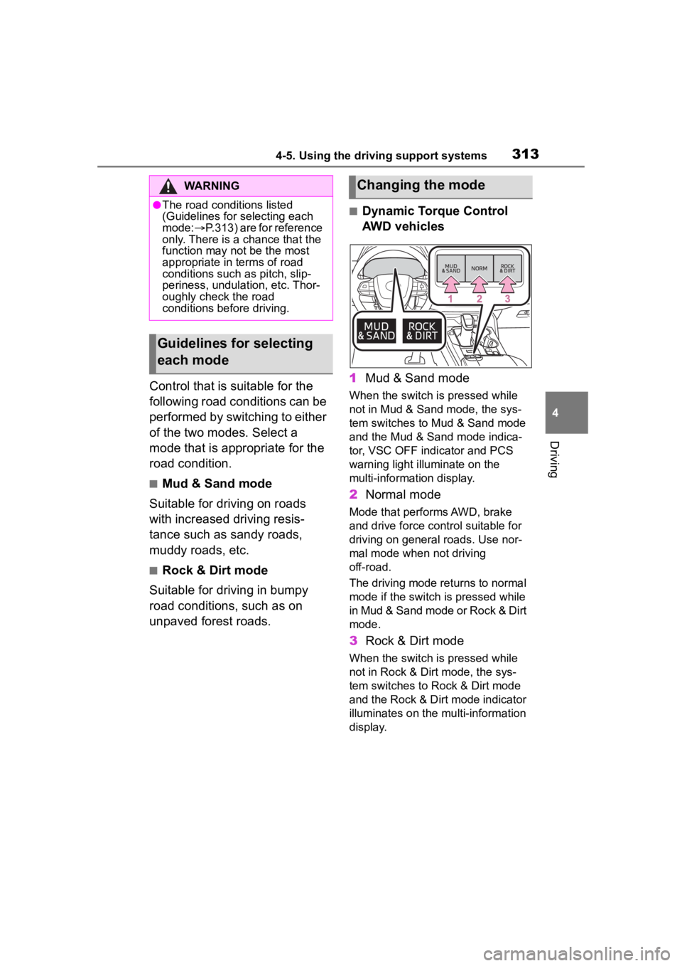
■Dynamic Torque Control
AWD vehicles
1 Mud & Sand mode
When the switch is pressed while
not in Mud & Sand mode, the sys-
tem switches to Mud & Sand mode
and the Mud & Sand mode indica-
tor, VSC OFF indi cator and PCS
warning light illuminate on the
multi-information display.
2 Normal mode
Mode that performs AWD, brake
and drive force cont rol suitable for
driving on general roads. Use nor-
mal mode when not driving
off-road.
The driving mode returns to normal
mode if the switch i s pressed while
in Mud & Sand mode or Rock & Dirt
mode.
3 Rock & Dirt mode
When the switch is pressed while
not in Rock & Dirt mode, the sys-
tem switches to Rock & Dirt mode
and the Rock & Dirt mode indicator
illuminates on the mu lti-information
display.
WARNING
●The road conditions listed
(Guidelines for selecting each
mode: P.313) are for reference
only. There is a chance that the
function may not be the most
appropriate in terms of road
conditions such as pitch, slip-
periness, undulation, etc. Thor-
oughly check the road
conditions before driving.
Guidelines for selecting
each mode
Changing the mode
Page 314 of 568
3144-5. Using the driving support systems
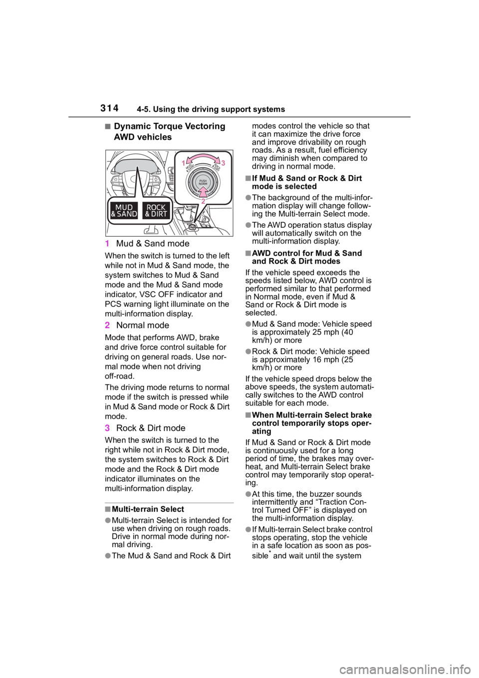
■Dynamic Torque Vectoring
AWD vehicles
1 Mud & Sand mode
When the switch is turned to the left
while not in Mud & Sand mode, the
system switches to Mud & Sand
mode and the Mud & Sand mode
indicator, VSC OFF indicator and
PCS warning light illuminate on the
multi-information display.
2Normal mode
Mode that performs AWD, brake
and drive force control suitable for
driving on general roads. Use nor-
mal mode when not driving
off-road.
The driving mode returns to normal
mode if the switch is pressed while
in Mud & Sand mode or Rock & Dirt
mode.
3Rock & Dirt mode
When the switch is turned to the
right while not in Rock & Dirt mode,
the system switches to Rock & Dirt
mode and the Rock & Dirt mode
indicator illuminates on the
multi-information display.
■Multi-terrain Select
●Multi-terrain Sele ct is intended for
use when driving on rough roads.
Drive in normal mode during nor-
mal driving.
●The Mud & Sand and Rock & Dirt modes control the
vehicle so that
it can maximize the drive force
and improve driv ability on rough
roads. As a result, fuel efficiency
may diminish when compared to
driving in normal mode.
■If Mud & Sand or Rock & Dirt
mode is selected
●The background of the multi-infor-
mation display will change follow-
ing the Multi-terrain Select mode.
●The AWD operation status display
will automatically switch on the
multi-information display.
■AWD control for Mud & Sand
and Rock & Dirt modes
If the vehicle speed exceeds the
speeds listed below, AWD control is
performed similar to that performed
in Normal mode, even if Mud &
Sand or Rock & Dirt mode is
selected.
●Mud & Sand mode: Vehicle speed
is approximately 25 mph (40
km/h) or more
●Rock & Dirt mode: Vehicle speed
is approximately 16 mph (25
km/h) or more
If the vehicle speed drops below the
above speeds, the system automati-
cally switches to the AWD control
suitable for each mode.
■When Multi-terrain Select brake
control temporarily stops oper-
ating
If Mud & Sand or Rock & Dirt mode
is continuously used for a long
period of time, th e brakes may over-
heat, and Multi-terrain Select brake
control may temporarily stop operat-
ing.
●At this time, the buzzer sounds
intermittently and “Traction Con-
trol Turned OFF” is displayed on
the multi-information display.
●If Multi-terrain Sele ct brake control
stops operating, stop the vehicle
in a safe location as soon as pos-
sible
* and wait until the system
Page 316 of 568
3164-5. Using the driving support systems
*: If equipped
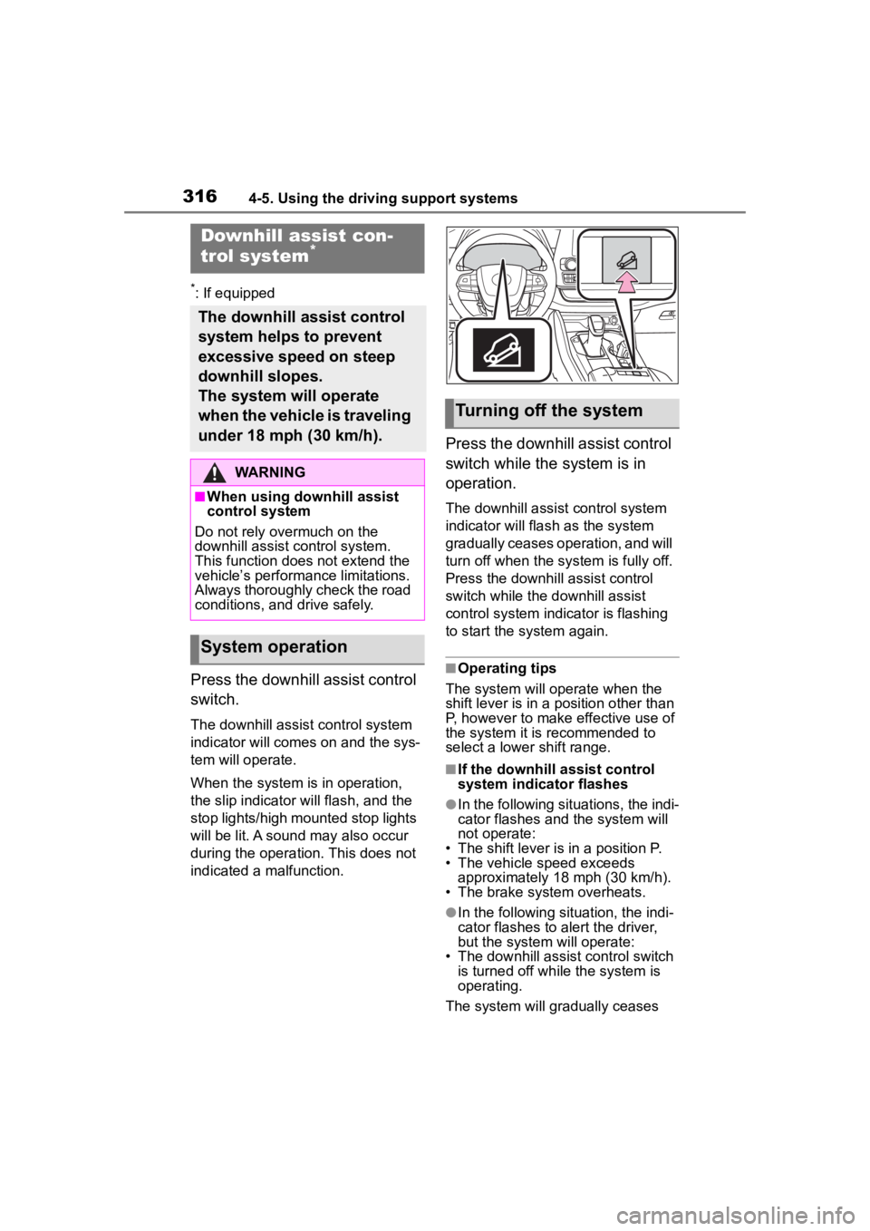
Press the downhill assist control
switch.
The downhill assist control system
indicator will comes on and the sys-
tem will operate.
When the system is in operation,
the slip indicator will flash, and the
stop lights/high mounted stop lights
will be lit. A sound may also occur
during the operation. This does not
indicated a malfunction.
Press the downhill assist control
switch while the system is in
operation.
The downhill assist control system
indicator will flash as the system
gradually ceases operation, and will
turn off when the system is fully off.
Press the downhill assist control
switch while the downhill assist
control system indicator is flashing
to start the system again.
■Operating tips
The system will o perate when the
shift lever is in a position other than
P, however to make effective use of
the system it is recommended to
select a lower shift range.
■If the downhill assist control
system indicator flashes
●In the following situ ations, the indi-
cator flashes and the system will
not operate:
• The shift lever is in a position P.
• The vehicle speed exceeds approximately 18 mph (30 km/h).
• The brake system overheats.
●In the following situation, the indi-
cator flashes to alert the driver,
but the system will operate:
• The downhill assist control switch is turned off while the system is
operating.
The system will gradually ceases
Downhill assist con-
trol system*
The downhill assist control
system helps to prevent
excessive speed on steep
downhill slopes.
The system will operate
when the vehicle is traveling
under 18 mph (30 km/h).
WARNING
■When using downhill assist
control system
Do not rely overmuch on the
downhill assist control system.
This function does not extend the
vehicle’s performance limitations.
Always thoroughly check the road
conditions, and drive safely.
System operation
Turning off the system