change time TOYOTA HIGHLANDER 2023 Owner's Manual
[x] Cancel search | Manufacturer: TOYOTA, Model Year: 2023, Model line: HIGHLANDER, Model: TOYOTA HIGHLANDER 2023Pages: 552, PDF Size: 13.36 MB
Page 220 of 552
2204-3. Operating the lights and wipers
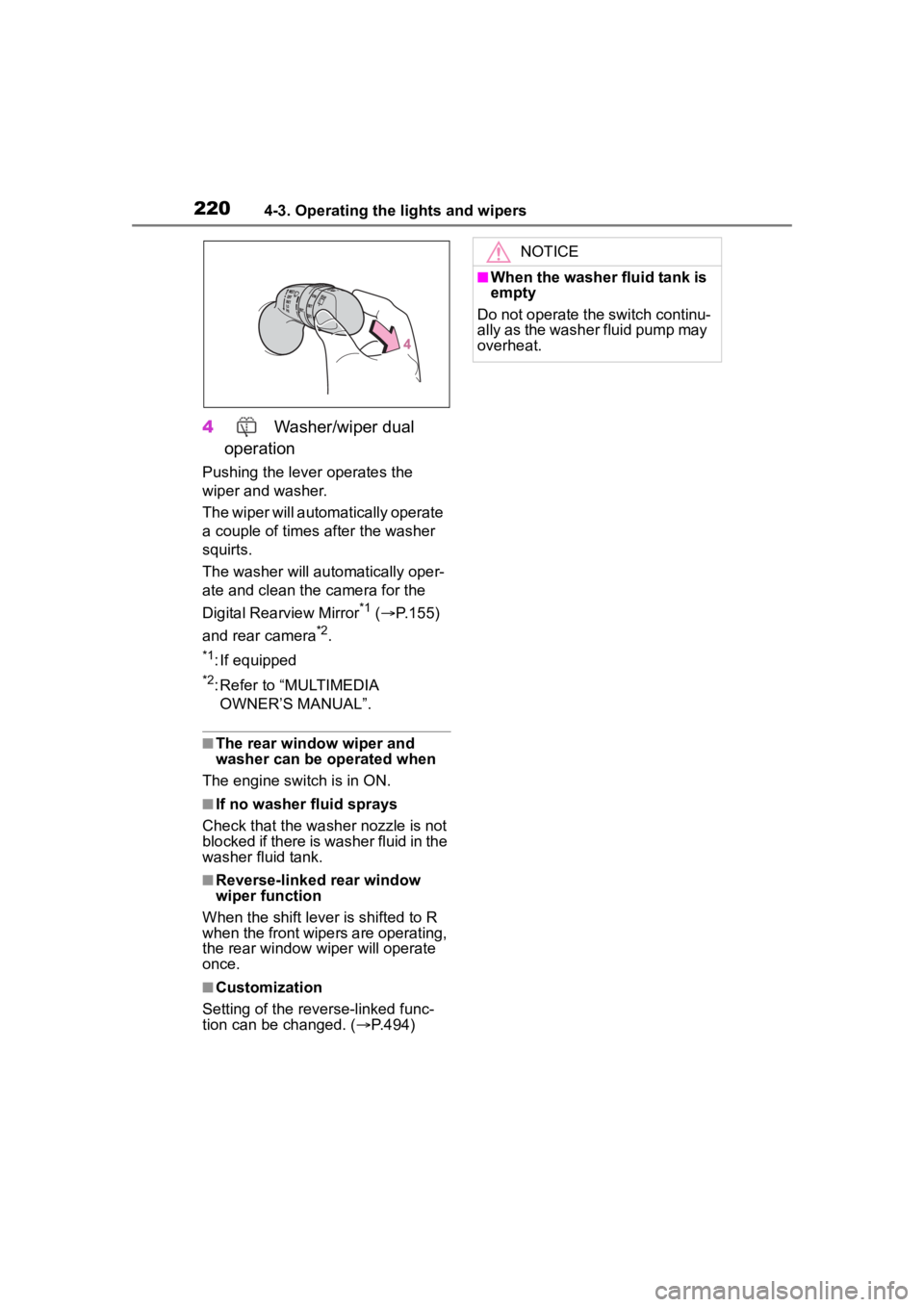
4 Washer/wiper dual
operation
Pushing the lever operates the
wiper and washer.
The wiper will automatically operate
a couple of times after the washer
squirts.
The washer will automatically oper-
ate and clean the camera for the
Digital Rearview Mirror
*1 ( P.155)
and rear camera
*2.
*1: If equipped
*2: Refer to “MULTIMEDIA OWNER’S MANUAL”.
■The rear window wiper and
washer can be operated when
The engine switch is in ON.
■If no washer fluid sprays
Check that the washer nozzle is not
blocked if there is washer fluid in the
washer fluid tank.
■Reverse-linked rear window
wiper function
When the shift lever is shifted to R
when the front wipers are operating,
the rear window wiper will operate
once.
■Customization
Setting of the reverse-linked func-
tion can be changed. ( P.494)
NOTICE
■When the washer fluid tank is
empty
Do not operate the switch continu-
ally as the washer fluid pump may
overheat.
Page 226 of 552
2264-5. Using the driving support systems
■If a warning message is displayed on the multi-information display
A system may be tempor arily unavailable or there may be a malfu nction in
the system.
●In the following situations, perform the actions specified in t he table. When
the normal operating conditions are detected, the message will disappear
and the system will be come operational.
If the message does not disapp ear, contact your Toyota dealer.
●In the following situations, if the situation has changed (or the vehicle has
been driven for some time) and the normal operating conditions are
detected, the message will disappear and the system will become opera-
tional.
SituationActions
When the area around a camera is
covered with dirt, moisture (fogged
up, covered with condensation, ice,
etc.), or other foreign matterUsing the wiper and A/C function,
remove the dirt and other attached
matter ( P.324).
When the temperature around the
front camera is out side of the opera-
tional range, such as when the vehi-
cle is in the sun or in an extremely
cold environment
If the front camera is hot, such as
after the vehicle had been parked in
the sun, use the air conditioning sys-
tem to decrease the temperature
around the front camera.
If a sunshade was used when the
vehicle was parked, depending on its
type, the sunlight r eflected from the
surface of the sunshade may cause
the temperature of the front camera
to become exce ssively high.
If the front camera is cold, such after
the vehicle is parked in an extremely
cold environment, use the air condi-
tioning system to increase the tem-
perature around the front camera.
The area in front of the front camera
is obstructed, such as when the
hood is open or a sticker is attached
to the part of the windshield in front
of the front camera.
Close the hood, remove the sticker,
etc. to clear the obstruction.
When “Pre-Collisi on System Radar
In Self Calibration Unavailable See
Owner's Manual” is displayed.Check whether there is attached
materials on the radar sensor and
radar sensor cover, and if there is,
remove it.
Page 232 of 552
2324-5. Using the driving support systems
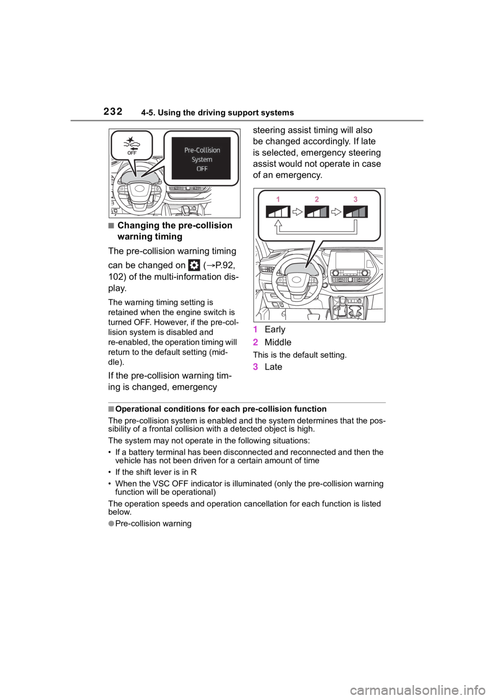
■Changing the pre-collision
warning timing
The pre-collision warning timing
can be changed on ( P.92,
102) of the multi-information dis-
play.
The warning timing setting is
retained when the engine switch is
turned OFF. However, if the pre-col-
lision system is disabled and
re-enabled, the operation timing will
return to the default setting (mid-
dle).
If the pre-collision warning tim-
ing is changed, emergency steering assist timing will also
be changed accordingly. If late
is selected, emergency steering
assist would not operate in case
of an emergency.
1
Early
2 Middle
This is the default setting.
3Late
■Operational conditions for e ach pre-collision function
The pre-collision syst em is enabled and the system determines t hat the pos-
sibility of a frontal c ollision with a detected object is high.
The system may not operate in the following situations:
• If a battery terminal has been disconnected and reconnected an d then the
vehicle has not been driven for a certain amount of time
• If the shift lever is in R
• When the VSC OFF indicator is illuminated (only the pre-collision warning
function will be operational)
The operation speeds and operati on cancellation for each function is listed
below.
●Pre-collision warning
Page 252 of 552
2524-5. Using the driving support systems
This mode employs a radar to detect the presence of vehicles up to
approximately 328 ft. (100 m) ahead, determines the current vehi-
cle-to-vehicle following distance, and operates to maintain a s uitable
following distance from the vehicle ahead. The desired vehi-
cle-to-vehicle distance can also be set by operating the vehi-
cle-to-vehicle distance switch.
When driving on downhill slopes, t he vehicle-to-vehicle distance may
become shorter.
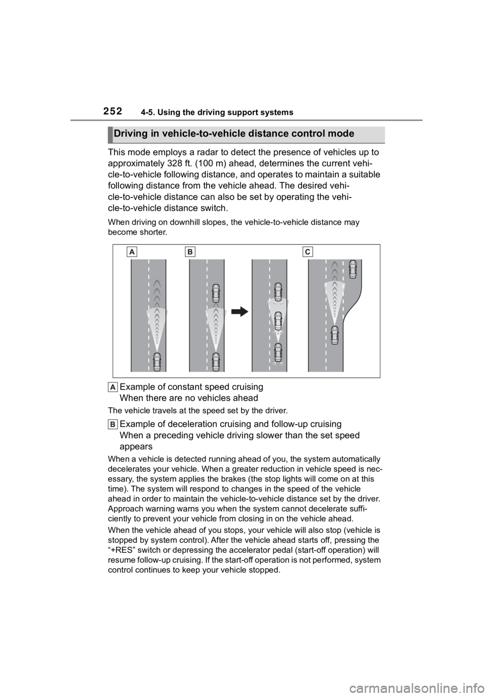
Example of constant speed cruising
When there are no vehicles ahead
The vehicle travels at the speed set by the driver.
Example of deceleration crui sing and follow-up cruising
When a preceding vehicle driving slower than the set speed
appears
When a vehicle is detected runni ng ahead of you, the system automatically
decelerates your vehicle. When a greater reduction in vehicle s peed is nec-
essary, the system applies the brakes (the stop lights will come on at this
time). The system will respond to changes in the speed of the vehicle
ahead in order to maintain the vehicle-to-vehicle distance set by the driver.
Approach warning warns you when the system cannot decelerate suffi-
ciently to prevent your vehicle from closing in on the vehicle ahead.
When the vehicle ahead of you st ops, your vehicle will also stop (vehicle is
stopped by system control). Afte r the vehicle ahead starts off, pressing the
“+RES” switch or depressing the accelerator pedal (start-off operation) will
resume follow-up cruising. If the start-off operation is not pe rformed, system
control continues to keep your vehicle stopped.
Driving in vehicle-to-vehicle distance control mode
Page 254 of 552
2544-5. Using the driving support systems
set speed.
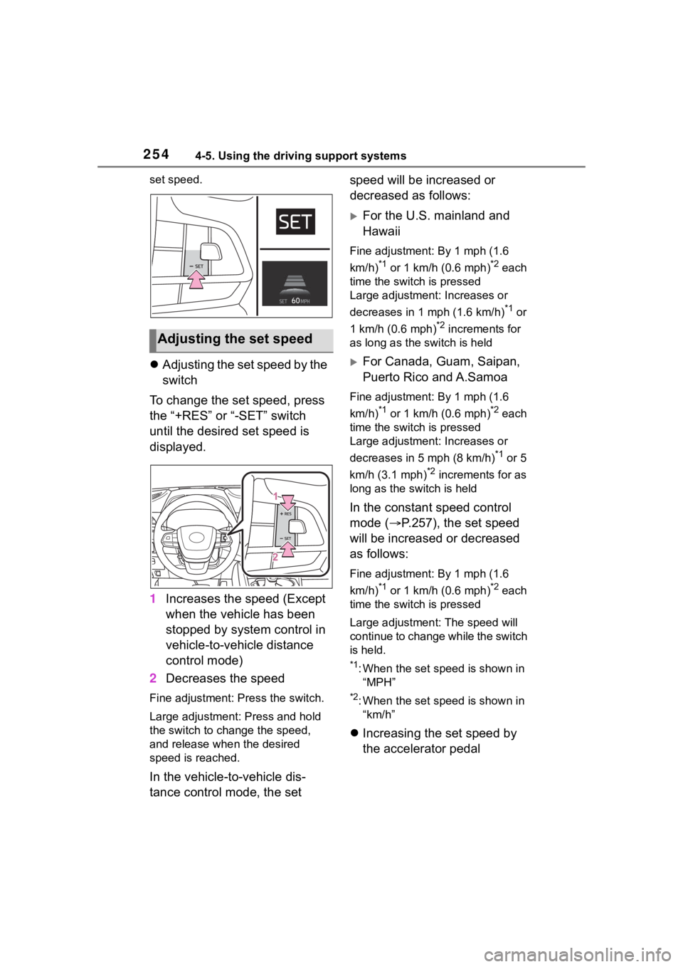
Adjusting the set speed by the
switch
To change the set speed, press
the “+RES” or “-SET” switch
until the desired set speed is
displayed.
1 Increases the speed (Except
when the vehicle has been
stopped by system control in
vehicle-to-vehicle distance
control mode)
2 Decreases the speed
Fine adjustment: Press the switch.
Large adjustment: Press and hold
the switch to change the speed,
and release when the desired
speed is reached.
In the vehicle-to-vehicle dis-
tance control mode, the set speed will be increased or
decreased as follows:
For the U.S. mainland and
Hawaii
Fine adjustment: By 1 mph (1.6
km/h)
*1 or 1 km/h (0.6 mph)*2 each
time the switch is pressed
Large adjustment: Increases or
decreases in 1 mph (1.6 km/h)
*1 or
1 km/h (0.6 mph)
*2 increments for
as long as the switch is held
For Canada, Guam, Saipan,
Puerto Rico and A.Samoa
Fine adjustment: By 1 mph (1.6
km/h)
*1 or 1 km/h (0.6 mph)*2 each
time the switch is pressed
Large adjustment: Increases or
decreases in 5 mph (8 km/h)
*1 or 5
km/h (3.1 mph)
*2 increments for as
long as the switch is held
In the constant speed control
mode ( P.257), the set speed
will be increased or decreased
as follows:
Fine adjustment: By 1 mph (1.6
km/h)
*1 or 1 km/h (0.6 mph)*2 each
time the switch is pressed
Large adjustmen t: The speed will
continue to change while the switch
is held.
*1: When the set speed is shown in “MPH”
*2: When the set speed is shown in “km/h”
Increasing the set speed by
the accelerator pedal
Adjusting the set speed
Page 257 of 552
2574-5. Using the driving support systems
4
Driving
the steering wheel is returned to
the center position, the vehicle
speed reduction will end.
Depending on the situation, the
vehicle speed will then return to
the vehicle-to-vehicle distance
control mode set speed.
In situations where vehi-
cle-to-vehicle distance control
needs to operate, such as when
a preceding vehicle cuts in front
of your vehicle, the curve speed
reduction function will be can-
celed.
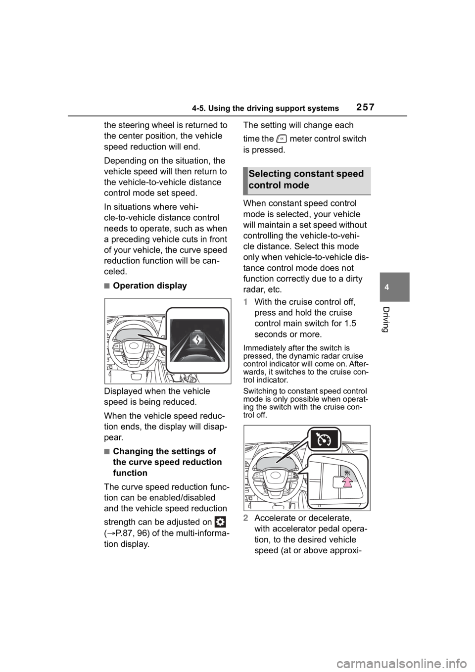
■Operation display
Displayed when the vehicle
speed is being reduced.
When the vehicle speed reduc-
tion ends, the display will disap-
pear.
■Changing the settings of
the curve speed reduction
function
The curve speed reduction func-
tion can be enabled/disabled
and the vehicle speed reduction
strength can be adjusted on
( P.87, 96) of the multi-informa-
tion display. The setting will change each
time the meter control switch
is pressed.
When constant speed control
mode is selected, your vehicle
will maintain a set speed without
controlling the vehicle-to-vehi-
cle distance. Select this mode
only when vehicle-
to-vehicle dis-
tance control mode does not
function correctly due to a dirty
radar, etc.
1 With the cruise control off,
press and hold the cruise
control main switch for 1.5
seconds or more.
Immediately after the switch is
pressed, the dynamic radar cruise
control indicator will come on. After-
wards, it switches to the cruise con-
trol indicator.
Switching to const ant speed control
mode is only possible when operat-
ing the switch with the cruise con-
trol off.
2 Accelerate or decelerate,
with accelerator pedal opera-
tion, to the desired vehicle
speed (at or above approxi-
Selecting constant speed
control mode
Page 259 of 552
2594-5. Using the driving support systems
4
Driving
■Automatic cancelation of con-
stant speed control mode
Constant speed control mode is
automatically cance led in the follow-
ing situations:
●Actual vehicle speed is more than
approximately 10 mph (16 km/h)
below the set vehicle speed.
●Actual vehicle speed falls below
approximately 20 mph (30 km/h).
●VSC is activated.
●TRAC is activated for a period of
time.
●When the VSC or TRAC system is
turned off.
●When the brake control or output
restriction control of a driving sup-
port system operates.
(For example: Pre-Collision Sys-
tem, Drive-Start Control)
●The parking brake is operated.
If constant speed control mode is
automatically canceled for any rea-
sons other than the above, there
may be a malfunction in the system.
Contact your Toyota dealer.
■Situations in which the curve
speed reduction function may
not operate
In situations such as the following,
the curve speed r eduction function
may not operate:
●When the vehicle is being driven
around a gentle curve
●When the accelerator pedal is
being depressed
●When the vehicle is being driven
around an extremely short curve
■Brake operation
A brake operation sound may be
heard and the brake pedal response
may change, but the se are not mal-
functions.
■Warning messages and buzzers
for dynamic radar cruise con-
trol with full-speed range
Warning messages and buzzers are
used to indicate a system malfunc-
tion or to inform the driver of the
need for caution while driving. If a
warning message is shown on the
multi-information display, read the
message and follow the instructions.
( P.226, 442)
■When the sensor may not be
correctly detecting the vehicle
ahead
In the case of the following and
depending on the conditions, oper-
ate the brake pedal when decelera-
tion of the system is insufficient or
operate the accelerator pedal when
acceleration is required.
As the sensor may not be able to
correctly detect th ese types of vehi-
cles, the approach warning
( P.256) may not be activated.
●Vehicles that cut in suddenly
●Vehicles traveling at low speeds
●Vehicles that are not moving in the
same lane
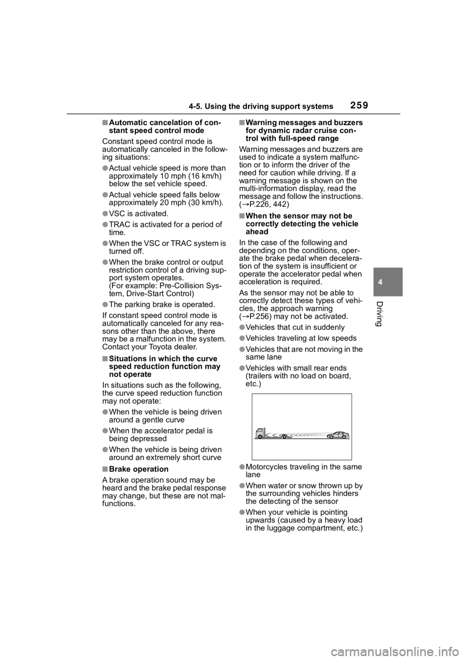
●Vehicles with small rear ends
(trailers with no load on board,
etc.)
●Motorcycles traveling in the same
lane
●When water or snow thrown up by
the surrounding vehicles hinders
the detecting of the sensor
●When your vehicle is pointing
upwards (caused by a heavy load
in the luggage compartment, etc.)
Page 263 of 552
2634-5. Using the driving support systems
4
Driving
■Conditions in which the func-
tion may not operate or detect
correctly
In the following situations, RSA
does not operate normally and may
not recognize signs, display the
incorrect sign, etc. However, this
does not indicate a malfunction.
●The front camera is misaligned
due to a strong impact being
applied to the sensor, etc.
●Dirt, snow, stickers, etc. are on the
windshield near the front camera.
●In inclement weather such as
heavy rain, fog, snow or sand
storms.
●Light from an oncoming vehicle,
the sun, etc. enters the front cam-
era.
●The sign is dirty, faded, tilted or
bent.
●The contrast of electronic sign is
low.
●All or part of the sign is hidden by
the leaves of a tree, a pole, etc.
●The sign is only visible to the front
camera for a short amount of time.
●The driving scene (turning, lane
change, etc.) is judged incorrectly.
●If a sign not appropriate for the
currently traveled lane, but the
sign exists directly after a freeway
branches, or in an adjacent lane
just before merging.
●Stickers are attached to the rear of
the preceding vehicle.
●A sign resembling a system com-
patible sign is recognized.
●Side road speed signs may be
detected and displayed (if posi-
tioned in sight of the front camera)
while the vehicle is traveling on
the main road.
●Roundabout exit road speed signs
may be detected and displayed (if
positioned in sight of the front
camera) while traveling on a
roundabout.
●The front of the vehicle is raised or
lowered due to the carried load.
●The surrounding brightness is not
sufficient or changes suddenly.
●When a sign inte nded for trucks,
etc. is recognized.
●The navigation system map data
is outdated.
●The navigation system is not oper-
ating.
●The speed information displayed
on the meter and on the naviga-
tion system may be different due
to the navigation system using
map data.
■Speed limit sign display
If the engine switch was last turned
off while a speed limit sign was dis-
played on the multi-information dis-
play, the same sig n displays again
when the engine switch is turned to
ON.
■If “RSA Malfunction Visit Your
Dealer” is shown
The system may be malfunctioning.
Have the vehicle inspected by your
Toyota dealer.
■Customization
Some functions can be customized.
(Customizable features: P.494)
Page 265 of 552

2654-5. Using the driving support systems
4
Driving
vehicle will remain stopped.
Press the Stop & Start cancel
switch to disable the Stop &
Start system.
The Stop & Start cancel indicator
will illuminate.
Pressing the switch again will
enable the Stop & Start system and
the Stop & Start cancel indicator will
turn off.
■Automatic enabling of the Stop
& Start system
If the Stop & Start system is dis-
abled using the Sto p & Start cancel
switch, it will be automatically
re-enabled once the engine switch
is turned off and t hen the engine is
started.
When the engine is stopped by
the Stop & Start system when
the vehicle is on an incline,
when the brake pedal is
released, brake force is tempo-
rarily maintained to prevent the
vehicle from rolling backwards
before the engine is restarted and drive force is generated.
When drive force is generated,
the maintained brake force is
automatically canceled.
This function operates on flat
surfaces as well as steep
inclines.
Sound may be generated
from the brake system, but
this does not indicate a mal-
function.
Brake pedal response may
change and vibration may
occur, but this does not indi-
cate a malfunction.
■Points for use
●If the engine switch is pressed
when the engine is stopped by the
Stop & Start system, the engine
will not be able to be restarted by
the automatic engine start func-
tion. In this case, restart the
engine using the normal engine
starting procedure. ( P.197)
●When the engine is being
restarted by the Stop & Start sys-
tem, the power ou tlets may be
temporarily unusable, but this
does not indicate a malfunction.
●Installation and removal of electri-
cal components and wireless
devices may affect the Stop &
Start system. Contact your Toyota
dealer for details.
●When stopping the vehicle for a
longer period of time, turn the
engine switch off to stop the
engine completely.
●When the engine is restarted by
the Stop & Start system, the steer-
ing wheel may temporarily feel
heavy.
Disabling the Stop & Start
system
Hill-start assist control
Page 266 of 552

2664-5. Using the driving support systems
■Operating conditions
●The Stop & Start system is opera-
tional when all of the following
conditions are met:
• The vehicle has been driven a cer-
tain amount of time.
• The brake pedal is being depressed firmly. (Except when
the vehicle is stopped by the
dynamic radar cruise control with
full-speed range when in vehi-
cle-to-vehicle distance control
mode)
• The D shift position is selected.
• The driver’s seat belt is fastened.
• The driver’s door is closed.
• The selected driving mode is
NORMAL or ECO mode.
• The selected driv ing mode is not
SNOW mode.
• The windshield defogger is off.
• The accelerator pedal is not being depressed.
• The engine is adequately warmed up.
• The hood is closed. ( P.267)
●In the following situations the
engine may not be stopped by the
Stop & Start system. This is not a
malfunction of the Stop & Start
system.
• When the air conditioning system is being used.
• When the battery is undergoing a
periodic recharge.
• When the battery is not sufficiently charged, such as if the vehicle
has been parked for a long time
and the battery charge has
decreased, the e lectric load is
large, the battery fluid tempera-
ture is excessively low or the bat-
tery has deteriorated.
• When the brake booster vacuum is low.
• When the elapsed time since the engine was restarted is short.
• When the vehicle is stopped fre- quently, such as when in a traffic
jam.
• When the engine coolant tem- perature or transmission fluid tem-
perature is extremely low or high. • When the vehicle
is stopped on a
steep incline.
• When the vehicle is being driven
in a high altitude area.
• When the battery fluid tempera- ture is extremely low or high.
• For a while after the battery termi- nals have been disconnected and
reconnected.
●When the engine is stopped by
the Stop & Star t system, the
engine will be restarted automati-
cally if any of the following condi-
tions are met: (To enable the
engine to be stopped by the Stop
& Start system aga in, drive the
vehicle.)
• The air conditioning system is being used.
• The windshield defogger is turned
on.
• The shift lever is shifted from D or P.
• The shift lever i s shifted from P.
(When the engine is stopped by
the Stop & Start system when the
shift lever is in P.)
• The driver’s seat belt is unfas- tened.
• The driver’s door is opened.
• The driving mode is changed from NORMAL or ECO mode to
another mode.
• The driving mode is changed to SNOW mode.
• The Stop & Start cancel switch is pressed.
• The accelerator pedal is
depressed.
• The vehicle starts to roll on an incline.
●When the engine is stopped by
the Stop & Star t system, the
engine may restart automatically
in the following situations: (To
enable the engine to be stopped
by the Stop & Start system again,
drive the vehicle.)
• When the brake pedal is pumped
or strongly depressed.
• When the air conditioning system is being used.
• When a switch of the air condition-