TOYOTA LAND CRUISER 2000 Owners Manual
Manufacturer: TOYOTA, Model Year: 2000, Model line: LAND CRUISER, Model: TOYOTA LAND CRUISER 2000Pages: 235, PDF Size: 5.13 MB
Page 121 of 235
L/C 100_U143
2000 L/C 100 (OM60866U)
Rear air conditioning on
−off button
To turn the rear air conditioning on, press
the ”REAR” button. To turn the rear air
conditioning off, press the button again.
”AUTO” Button
For automatic operation of the rear air
conditioning, press the ”AUTO” button. An
indicator light will illuminate to show that
the automatic operation mode has been
selected.
In the automatic operation mode, the rear
air conditioning selects the most suitable
fan speed and air flow according to the
temperature.
You may use manual controls if you want
to select your own settings.
To turn off the automatic operation, press
the ”OFF” button.
Fan speed selector
Press the buttons to adjust the fan speed.
In automatic operation, you do not have
to adjust the fan speed unless you desire
another fan speed mode. Temperature selector
Move the lever to adjust the tempera-
ture—to the right to warm, to the left to
cool.
”OFF” button
Push the button to turn off the rear air
conditioning system.
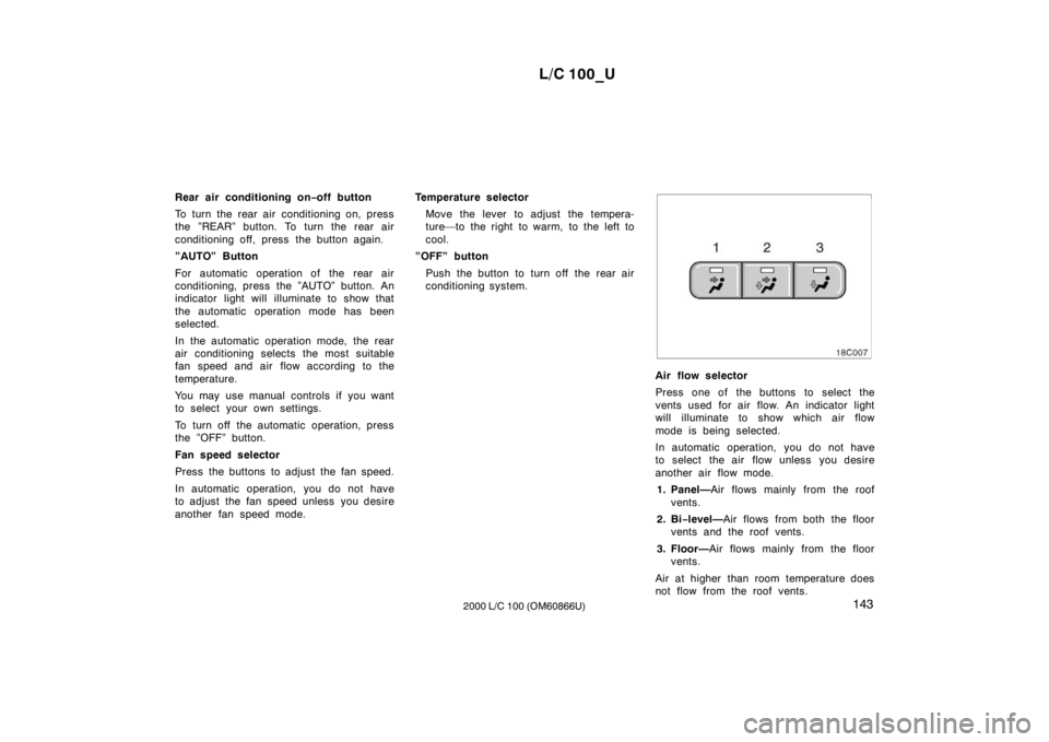
Air flow selector
Press one of the buttons to select the
vents used for air flow. An indicator light
will illuminate to show which air flow
mode is being selected.
In automatic operation, you do not have
to select the air flow unless you desire
another air flow mode.1. Panel— Air flows mainly from the roof
vents.
2. Bi −level— Air flows from both the floor
vents and the roof vents.
3. Floor— Air flows mainly from the floor
vents.
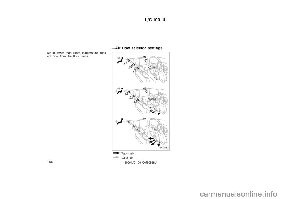
Air at higher than room temperature does
not flow from the roof vents.
Page 122 of 235
L/C 100_U
144 2000 L/C 100 (OM60866U)
Air at lower than room temperature does
not flow from the floor vents.
—Air flow selector settings
Warm air
Cool air
Page 123 of 235

L/C 100_U145
2000 L/C 100 (OM60866U) OPERATION OF INSTRUMENTS AND
CONTROLS
Other equipment
Clock146
. . . . . . . . . . . . . . . . . . . . . . . . . . . . . . . . . . . . . . . . . . . . . . . . . . . . . .
Outside temperature display146
. . . . . . . . . . . . . . . . . . . . . . . . . . . . . . . . .
Cigarette lighter and ashtray147
. . . . . . . . . . . . . . . . . . . . . . . . . . . . . . . . .
Power outlets147
. . . . . . . . . . . . . . . . . . . . . . . . . . . . . . . . . . . . . . . . . . . . . .
Fuel pump shut −off system148
. . . . . . . . . . . . . . . . . . . . . . . . . . . . . . . . . .
Rear console box149
. . . . . . . . . . . . . . . . . . . . . . . . . . . . . . . . . . . . . . . . . . .
Glove box150
. . . . . . . . . . . . . . . . . . . . . . . . . . . . . . . . . . . . . . . . . . . . . . . . . .
Garage door opener box150
. . . . . . . . . . . . . . . . . . . . . . . . . . . . . . . . . . . .
Auxiliary boxes153
. . . . . . . . . . . . . . . . . . . . . . . . . . . . . . . . . . . . . . . . . . . . .
Cup holders156
. . . . . . . . . . . . . . . . . . . . . . . . . . . . . . . . . . . . . . . . . . . . . . . .
Tie −down hooks157
. . . . . . . . . . . . . . . . . . . . . . . . . . . . . . . . . . . . . . . . . . . .
Luggage cover158
. . . . . . . . . . . . . . . . . . . . . . . . . . . . . . . . . . . . . . . . . . . . .
Floor mat159
. . . . . . . . . . . . . . . . . . . . . . . . . . . . . . . . . . . . . . . . . . . . . . . . . .
SECTION 1− 9
Page 124 of 235
L/C 100_U
146 2000 L/C 100 (OM60866U)
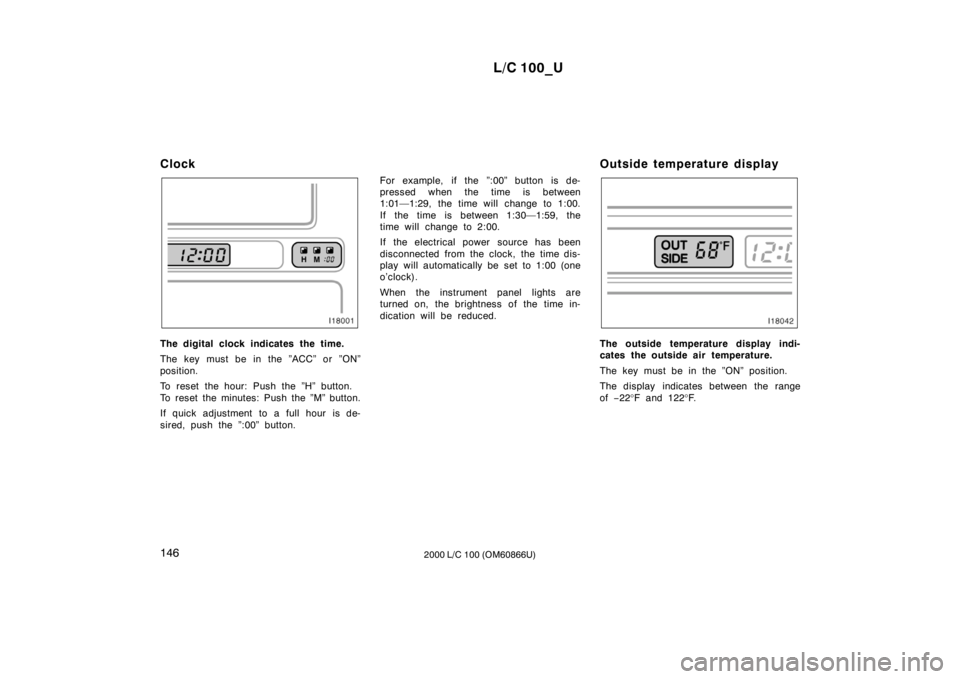
Clock
The digital clock indicates the time.
The key must be in the ”ACC” or ”ON”
position.
To reset the hour: Push the ”H” button.
To reset the minutes: Push the ”M” button.
If quick adjustment to a full hour is de-
sired, push the ”:00” button.
For example, if the ”:00” button is de-
pressed when the time is between
1:01—1:29, the time will change to 1:00.
If the time is between 1:30—1:59, the
time will change to 2:00.
If the electrical power source has been
disconnected from the clock, the time dis-
play will automatically be set to 1:00 (one
o’clock).
When the instrument panel lights are
turned on, the brightness of the time in-
dication will be reduced.
Outside temperature displayThe outside temperature display indi-
cates the outside air temperature.
The key must be in the ”ON” position.
The display indicates between the range of
−22 °F and 122 °F.
Page 125 of 235
L/C 100_U147
2000 L/C 100 (OM60866U)
Cigarette lighter and ashtray
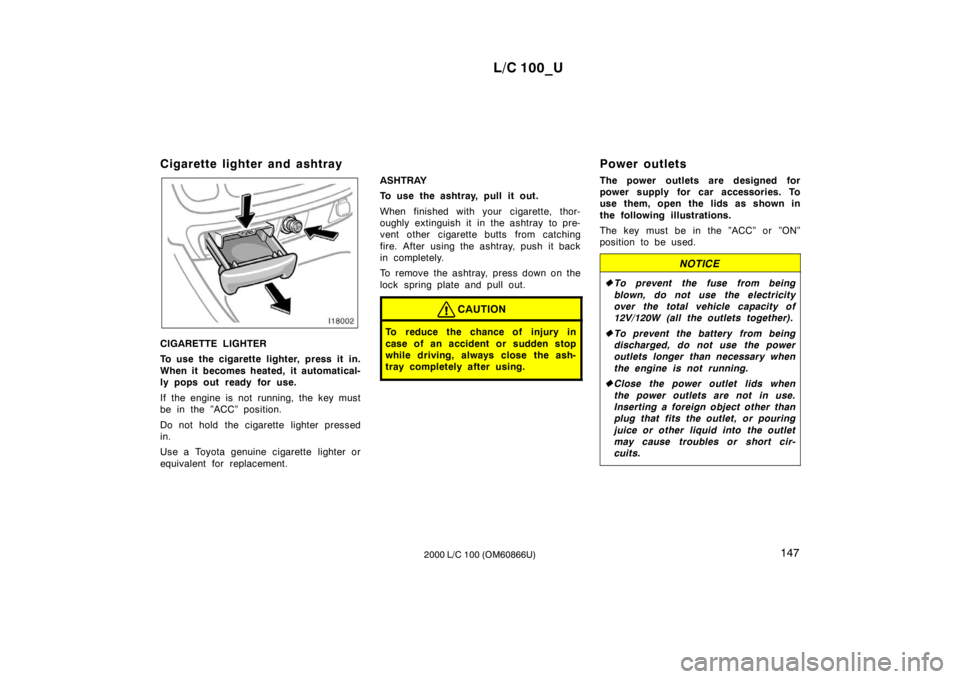
CIGARETTE LIGHTER
To use the cigarette lighter, press it in.
When it becomes heated, it automatical-
ly pops out ready for use.
If the engine is not running, the key must
be in the ”ACC” position.
Do not hold the cigarette lighter pressed
in.
Use a Toyota genuine cigarette lighter or
equivalent for replacement.
ASHTRAY
To use the ashtray, pull it out.
When finished with your cigarette, thor-
oughly extinguish it in the ashtray to pre-
vent other cigarette butts from catching
fire. After using the ashtray, push it back
in completely.
To remove the ashtray, press down on the
lock spring plate and pull out.
CAUTION
To reduce the chance of injury in
case of an accident or sudden stop
while driving, always close the ash-
tray completely after using.
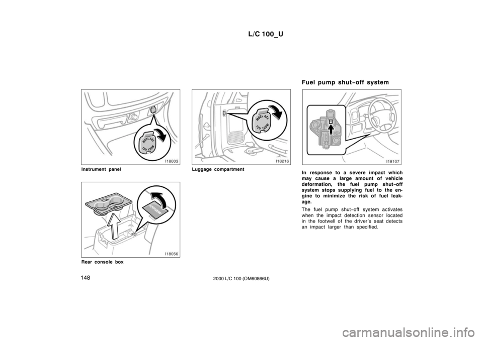
Power outlets
The power outlets are designed for
power supply for car accessories. To
use them, open the lids as shown in
the following illustrations.
The key must be in the ”ACC” or ”ON”
position to be used.
NOTICE
�
To prevent the fuse from being
blown, do not use the electricity
over the total vehicle capacity of
12V/120W (all the outlets together).
� To prevent the battery from being
discharged, do not use the power
outlets longer than necessary when
the engine is not running.
� Close the power outlet lids when
the power outlets are not in use.
Inserting a foreign object other than
plug that fits the outlet, or pouring
juice or other liquid into the outlet
may cause troubles or short cir-
cuits.
Page 126 of 235
L/C 100_U
148 2000 L/C 100 (OM60866U)
Instrument panel
Rear console box
Luggage compartmentFuel pump shut
−off systemIn response to a severe impact which
may cause a large amount of vehicle
deformation, the fuel pump shut −off
system stops supplying fuel to the en-
gine to minimize the risk of fuel leak- age.
The fuel pump shut −off system activates
when the impact detection sensor located
in the footwell of the driver’s seat detects
an impact larger than specified.
Page 127 of 235
L/C 100_U149
2000 L/C 100 (OM60866U)
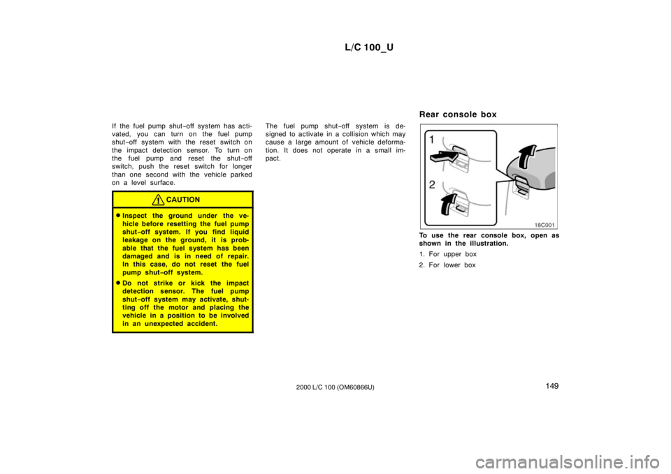
If the fuel pump shut
−off system has acti-
vated, you can turn on the fuel pump
shut −off system with the reset switch on
the impact detection sensor. To turn on
the fuel pump and reset the shut −off
switch, push the reset switch for longer
than one second with the vehicle parked
on a level surface.
CAUTION
� Inspect the ground under the ve-
hicle before resetting the fuel pump shut −off system. If you find liquid
leakage on the ground, it is prob-
able that the fuel system has been
damaged and is in need of repair.
In this case, do not reset the fuel
pump shut −off system.
� Do not strike or kick the impact
detection sensor. The fuel pump shut −off system may activate, shut-
ting off the motor and placing the
vehicle in a position to be involved
in an unexpected accident.
The fuel pump shut −off system is de-
signed to activate in a collision which may
cause a large amount of vehicle deforma-
tion. It does not operate in a small im-
pact. Rear console box
To use the rear console box, open as
shown in the illustration.
1. For upper box
2. For lower box
Page 128 of 235
L/C 100_U
150 2000 L/C 100 (OM60866U)
Glove box
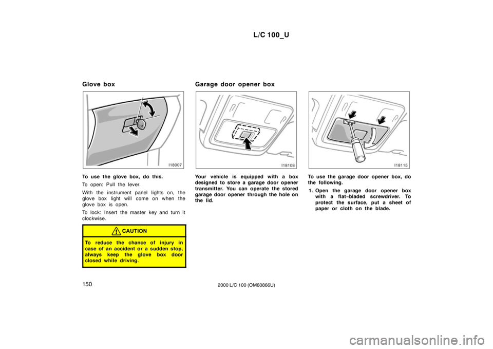
To use the glove box, do this.
To open: Pull the lever.
With the instrument panel lights on, the
glove box light will come on when the
glove box is open.
To lock: Insert the master key and turn it
clockwise.
CAUTION
To reduce the chance of injury in
case of an accident or a sudden stop,
always keep the glove box door
closed while driving.
Garage door opener box
Your vehicle is equipped with a box
designed to store a garage door opener
transmitter. You can operate the stored
garage door opener through the hole on
the lid.To use the garage door opener box, do
the following.
1. Open the garage door opener box with a flat −bladed screwdriver. To
protect the surface, put a sheet of
paper or cloth on the blade.
Page 129 of 235
L/C 100_U151
2000 L/C 100 (OM60866U)
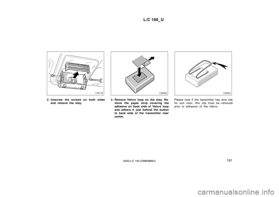
2. Unscrew the screws on both sides
and remove the stay.3. Remove Velcro loop on the stay. Re-move the paper strip covering the
adhesive on back side of Velcro loop
and adhere it just behind the button
to back side of the transmitter near
center.Please note if the transmitter has wire clip
for sun visor, this clip must be removed
prior to adhesion of the Velcro.
Page 130 of 235
L/C 100_U
152 2000 L/C 100 (OM60866U)
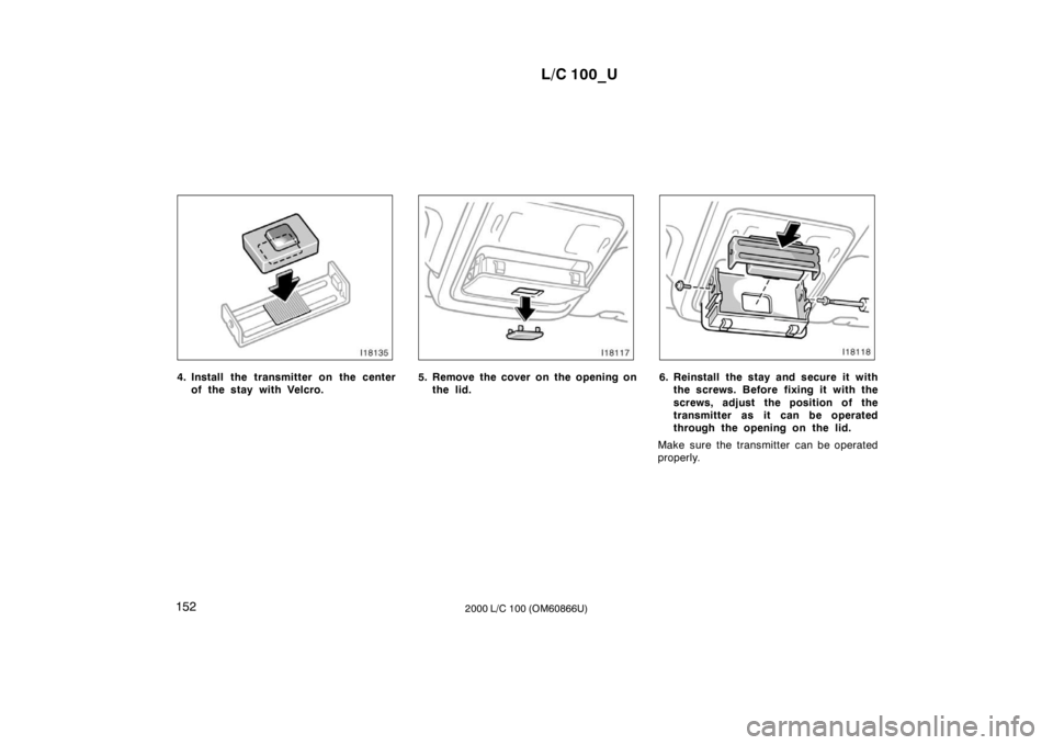
4. Install the transmitter on the center
of the stay with Velcro.5. Remove the cover on the opening onthe lid.6. Reinstall the stay and secure it withthe screws. Before fixing it with the
screws, adjust the position of the
transmitter as it can be operated
through the opening on the lid.
Make sure the transmitter can be operated
properly.