air condition TOYOTA LAND CRUISER 2013 J200 Service Manual
[x] Cancel search | Manufacturer: TOYOTA, Model Year: 2013, Model line: LAND CRUISER, Model: TOYOTA LAND CRUISER 2013 J200Pages: 720, PDF Size: 21.46 MB
Page 507 of 720
507 3-7. Other interior features
3
Interior features
LC200_OM_OM60F57U_(U)
Safety Connect LED light Indicators
When the “ENGINE START STOP” switch is turned to IGNITION ON
mode, the red indicator light comes on for 2 seconds then turns off.
Afterward, the green indicator light comes on, indicating that the ser-
vice is active.
The following indicator light patterns indicate specific system usage
conditions:
●Green indicator light on = Active service
●Green indicator light flashing = Safety Connect call in process
●Red indicator light (except at vehicle start-up) = System malfunc-
tion (contact your Toyota dealer)
●No indicator light (off) = Safety Connect service not active
Safety Connect services
■Automatic Collision Notification
In case of either airbag deployment or severe rear-end collision,
the system is designed to automatically call the response center.
The responding agent receives the vehicle’s location and attempts
to speak with the vehicle occupants to assess the level of emer-
gency. If the occupants are unable to communicate, the agent
automatically treats the call as an emergency, contacts the nearest
emergency services provider to describe the situation, and
requests that assistance be sent to the location.
Page 511 of 720
Maintenance and care4
511
LC200_OM_OM60F57U_(U)
4-1. Maintenance and care
Cleaning and protecting
the vehicle exterior ......... 512
Cleaning and protecting
the vehicle interior .......... 515
4-2. Maintenance
Maintenance
requirements .................. 518
General maintenance....... 520
Emission inspection
and maintenance (I/M)
programs ........................ 523
4-3. Do-it-yourself maintenance
Do-it-yourself service
precautions .................... 524
Hood ................................ 527
Engine compartment ........ 528
Tires ................................. 544
Tire inflation pressure ...... 553
Wheels ............................. 557
Air conditioning filter......... 560
Electronic key battery....... 563
Checking and
replacing fuses ............... 566
Headlight aim ................... 579
Light bulbs........................ 581
Page 526 of 720
526 4-3. Do-it-yourself maintenance
LC200_OM_OM60F57U_(U)
CAUTION
The engine compartment contains many mechanisms and fluids that may
move suddenly, become hot, or become electrically energized. To avoid death
or serious injury.
■When working on the engine compartment
●Keep hands, clothing, and tools away from the moving fan and engine
drive belt.
●Be careful not to touch the engine, inverter, radiator, exhaust manifold, etc.
right after driving as they may be hot. Oil and other fluids may also be hot.
●Do not leave anything that may burn easily, such as paper or rags, in the
engine compartment.
●Do not smoke, cause sparks or expose an open flame to fuel or the bat-
tery. Fuel and battery fumes are flammable.
●Be extremely cautious when working on the battery. It contains poisonous
and corrosive sulfuric acid.
■When working near the electric cooling fan or radiator grille
Be sure the “ENGINE START STOP” switch is OFF.
With the “ENGINE START STOP” switch in IGNITION ON mode, the electric
cooling fan may automatically start to run if the air conditioning is on and/or if
the coolant temperature is high. (P. 535)
■When working on or under the vehicle
●Do not get under the vehicle with just the jack supporting it.
Always use automotive jack stands or other solid supports.
●Use eye protection to prevent flying or falling material, fluid spray, etc. from
getting in your eyes.
NOTICE
■If you remove the air cleaner filter
Driving with the air cleaner filter removed may cause excessive engine wear
due to dirt in the air.
Page 552 of 720

552 4-3. Do-it-yourself maintenance
LC200_OM_OM60F57U_(U)
NOTICE
■Repairing or replacing tires, wheels, tire pressure warning valves
and transmitters and tire valve caps
●When removing or fitting the wheels, tires or the tire pressure warning
valve and transmitter, contact your Toyota dealer as the tire pressure
warning valve and transmitter may be damaged if not handled cor-
rectly.
●When replacing tire valve caps, do not use tire valve caps other than
those specified. The cap may become stuck.
■To avoid damage to the tire pressure warning valves and transmit-
ters
When a tire is repaired with liquid sealants, the tire pressure warning
valve and transmitter may not operate properly. If a liquid sealant is
used, contact your Toyota dealer or other qualified service shop as soon
as possible. Make sure to replace the tire pressure warning valve and
transmitter when replacing the tire. (P. 545)
■Driving on rough roads
Take particular care when driving on roads with loose surfaces or pot-
holes.
These conditions may cause losses in tire inflation pressure, reducing
the cushioning ability of the tires. In addition driving on rough roads may
cause damage to the tires themselves, as well as the vehicle’s wheels
and body.
■If tire inflation pressures become low while driving
Do not continue driving, or your tires and/or wheels may be ruined.
Page 556 of 720
556 4-3. Do-it-yourself maintenance
LC200_OM_OM60F57U_(U)
CAUTION
■Proper inflation is critical to save tire performance
Keep your tires properly inflated. Otherwise, the following conditions
may occur and result in an accident causing death or serious injury.
●Excessive wear
●Uneven wear
●Poor handling
●Possibility of blowouts resulting from overheated tires
●Poor sealing of the tire bead
●Wheel deformation and/or tire separation
●A greater possibility of tire damage from road hazards
NOTICE
■When inspecting and adjusting tire inflation pressure
Be sure to reinstall the tire valve caps.
Without the valve caps, dirt or moisture could get into the valve and
cause air leakage, which could result in an accident. If the caps have
been lost, replace them as soon as possible.
Page 560 of 720
560
4-3. Do-it-yourself maintenance
LC200_OM_OM60F57U_(U)
Air conditioning filter
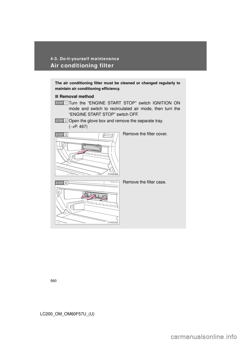
The air conditioning filter must be cleaned or changed regularly to
maintain air conditioning efficiency.
■Removal method
Turn the “ENGINE START STOP” switch IGNITION ON
mode and switch to recirculated air mode, then turn the
“ENGINE START STOP” switch OFF.
Open the glove box and remove the separate tray.
(P. 467)
Remove the filter cover.
Remove the filter case.
STEP1
STEP2
STEP3
ITY43C030
STEP4
Page 561 of 720
561 4-3. Do-it-yourself maintenance
4
Maintenance and care
LC200_OM_OM60F57U_(U)
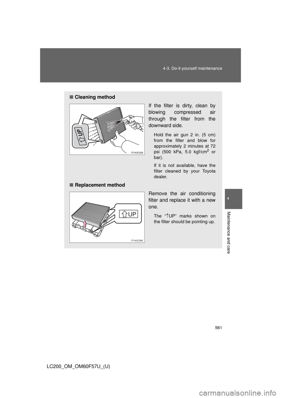
■Cleaning method
If the filter is dirty, clean by
blowing compressed air
through the filter from the
downward side.
Hold the air gun 2 in. (5 cm)
from the filter and blow for
approximately 2 minutes at 72
psi (500 kPa, 5.0 kgf/cm
2 or
bar).
If it is not available, have the
filter cleaned by your Toyota
dealer.
■Replacement method
Remove the air conditioning
filter and replace it with a new
one.
The “UP” marks shown on
the filter should be pointing up.
UP
UP
UP
ITY43C090
Page 562 of 720

562 4-3. Do-it-yourself maintenance
LC200_OM_OM60F57U_(U)
■Checking interval
Inspect, clean and replace the air conditioning filter according to the mainte-
nance schedule. In dusty areas or areas with heavy traffic flow, more fre-
quent cleaning or early replacement may be required. (For scheduled
maintenance information, read the “Scheduled Maintenance Guide”,
“Owner’s Manual Supplement”.)
■If air flow from the vents decreases dramatically
The filter may be clogged. Check the filter and replace if necessary.
NOTICE
■To prevent damage to the system
●When using the air conditioning system, make sure that a filter is always
installed.
●When cleaning the filter, do not clean the filter with water.
Page 571 of 720
571 4-3. Do-it-yourself maintenance
4
Maintenance and care
LC200_OM_OM60F57U_(U)
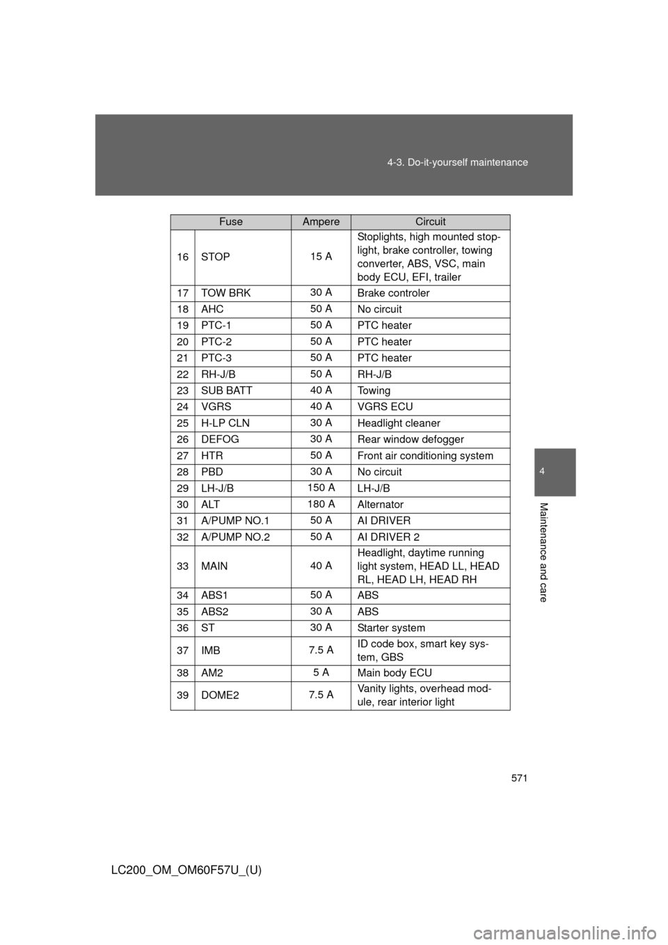
16STOP15 AStoplights, high mounted stop-
light, brake controller, towing
converter, ABS, VSC, main
body ECU, EFI, trailer
17TOW BRK30 A
Brake controler
18AHC50 A
No circuit
19PTC-150 A
PTC heater
20PTC-250 A
PTC heater
21PTC-350 A
PTC heater
22RH-J/B50 A
RH-J/B
23SUB BATT40 A
To w i n g
24VGRS40 A
VGRS ECU
25H-LP CLN30 A
Headlight cleaner
26DEFOG30 A
Rear window defogger
27HTR50 A
Front air conditioning system
28PBD30 A
No circuit
29LH-J/B150 A
LH-J/B
30ALT180 A
Alternator
31A/PUMP NO.150 A
AI DRIVER
32A/PUMP NO.250 A
AI DRIVER 2
33MAIN40 AHeadlight, daytime running
light system, HEAD LL, HEAD
RL, HEAD LH, HEAD RH
34ABS150 A
ABS
35ABS230 A
ABS
36ST30 A
Starter system
37IMB7.5 AID code box, smart key sys-
tem, GBS
38AM25 A
Main body ECU
39DOME27.5 AVanity lights, overhead mod-
ule, rear interior light
FuseAmpereCircuit
Page 574 of 720
574 4-3. Do-it-yourself maintenance
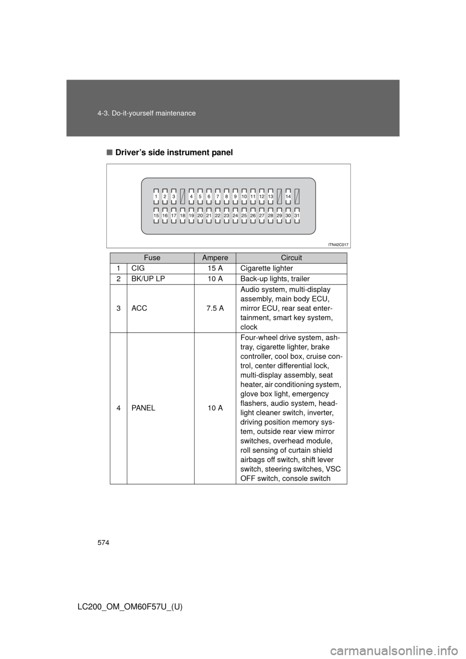
LC200_OM_OM60F57U_(U)■Driver’s side instrument panel
FuseAmpereCircuit
1CIG15 A Cigarette lighter
2BK/UP LP10 A Back-up lights, trailer
3ACC7.5 AAudio system, multi-display
assembly, main body ECU,
mirror ECU, rear seat enter-
tainment, smart key system,
clock
4PA N E L10 AFour-wheel drive system, ash-
tray, cigarette lighter, brake
controller, cool box, cruise con-
trol, center differential lock,
multi-display assembly, seat
heater, air conditioning system,
glove box light, emergency
flashers, audio system, head-
light cleaner switch, inverter,
driving position memory sys-
tem, outside rear view mirror
switches, overhead module,
roll sensing of curtain shield
airbags off switch, shift lever
switch, steering switches, VSC
OFF switch, console switch