TOYOTA LAND CRUISER 2018 Owners Manual (in English)
Manufacturer: TOYOTA, Model Year: 2018, Model line: LAND CRUISER, Model: TOYOTA LAND CRUISER 2018Pages: 620, PDF Size: 12.04 MB
Page 341 of 620
LC200_OM_OM60Q26U_(U)
3414-5. Using the driving support systems
4
Driving
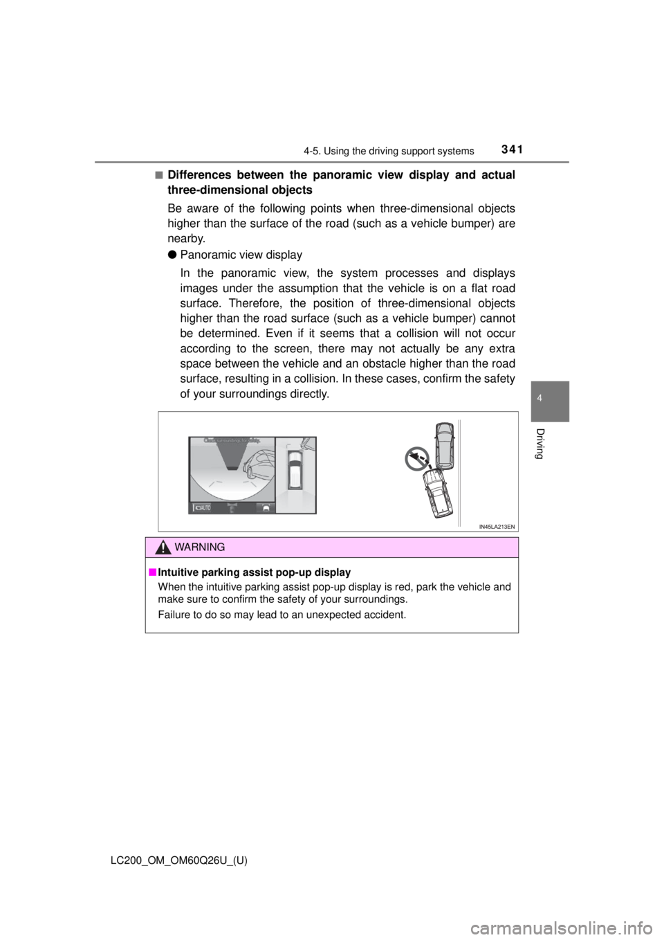
■Differences between the panoramic view display and actual
three-dimensional objects
Be aware of the following points when three-dimensional objects
higher than the surface of the ro ad (such as a vehicle bumper) are
nearby.
● Panoramic view display
In the panoramic view, the system processes and displays
images under the assumption that the vehicle is on a flat road
surface. Therefore, the position of three-dimensional objects
higher than the road surface (such as a vehicle bumper) cannot
be determined. Even if it seems that a collision will not occur
according to the screen, there may not actually be any extra
space between the vehicle and an obstacle higher than the road
surface, resulting in a collision. In these cases, confirm the safety
of your surroundings directly.
WARNING
■ Intuitive parking assist pop-up display
When the intuitive parking assist pop-up display is red, park the vehicle and
make sure to confirm the safety of your surroundings.
Failure to do so may lead to an unexpected accident.
Page 342 of 620
342
LC200_OM_OM60Q26U_(U)
4-5. Using the driving support systems
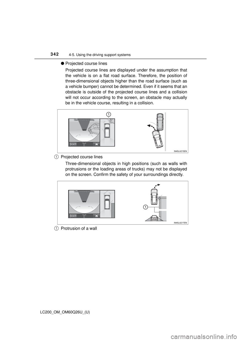
●Projected course lines
Projected course lines are displayed under the assumption that
the vehicle is on a flat road su rface. Therefore, the position of
three-dimensional objects higher than the road surface (such as
a vehicle bumper) cannot be deter mined. Even if it seems that an
obstacle is outside of the projec ted course lines and a collision
will not occur according to the screen, an obstacle may actually
be in the vehicle course, resulting in a collision.
Projected course lines Three-dimensional objects in high positions (such as walls with
protrusions or the loading areas of trucks) may not be displayed
on the screen. Confirm the safety of your surroundings directly.
Protrusion of a wall
1
1
Page 343 of 620
LC200_OM_OM60Q26U_(U)
3434-5. Using the driving support systems
4
Driving
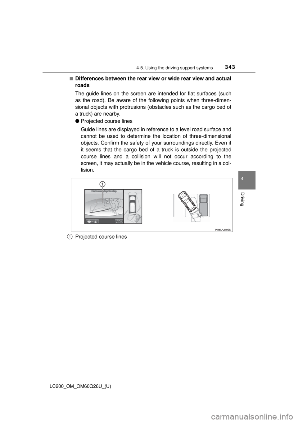
■Differences between the rear view or wide rear view and actual
roads
The guide lines on the screen are intended for flat surfaces (such
as the road). Be aware of the following points when three-dimen-
sional objects with protrusions ( obstacles such as the cargo bed of
a truck) are nearby.
● Projected course lines
Guide lines are displayed in reference to a level road surface and
cannot be used to determine th e location of three-dimensional
objects. Confirm the safety of your surroundings directly. Even if
it seems that the cargo bed of a truck is outside the projected
course lines and a collision will not occur according to the
screen, it may actually be in the vehicle course, resulting in a col-
lision.
Projected course lines
1
Page 344 of 620
344
LC200_OM_OM60Q26U_(U)
4-5. Using the driving support systems
■Differences between the panoramic view, rear view and wide
rear view and actual roads
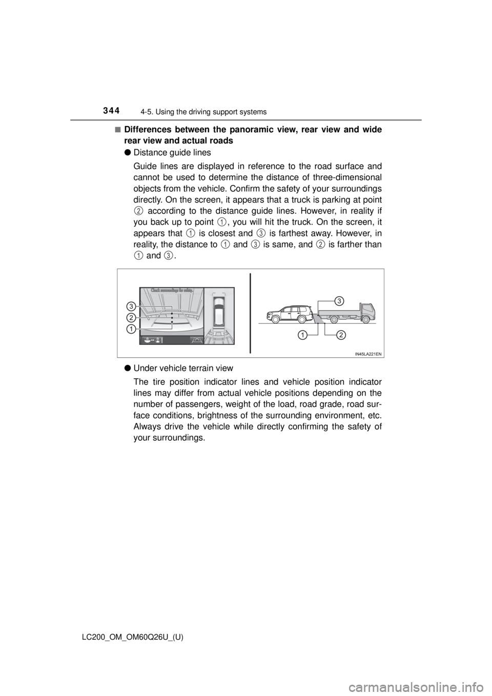
●Distance guide lines
Guide lines are displayed in reference to the road surface and
cannot be used to determine th e distance of three-dimensional
objects from the vehicle. Confirm the safety of your surroundings
directly. On the screen, it appears that a truck is parking at point according to the distance guide lines. However, in reality if
you back up to point , you will hit the truck. On the screen, it
appears that is closest and is farthest away. However, in
reality, the distance to and is same, and is farther than and .
● Under vehicle terrain view
The tire position indicator lines and vehicle position indicator
lines may differ from actual v ehicle positions depending on the
number of passengers, weight of the load, road grade, road sur-
face conditions, brightness of the surrounding environment, etc.
Always drive the vehicle while directly confirming the safety of
your surroundings.
2
1
13
132
13
Page 345 of 620
LC200_OM_OM60Q26U_(U)
3454-5. Using the driving support systems
4
Driving
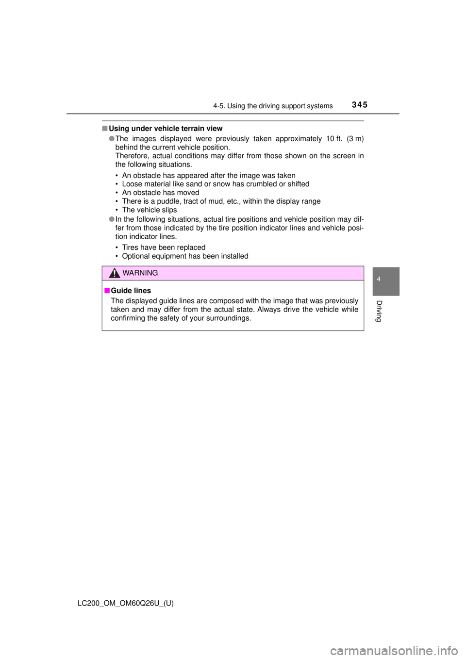
■Using under vehicle terrain view
●The images displayed were previously taken approximately 10 ft. (3 m)
behind the current vehicle position.
Therefore, actual conditions may differ from those shown on the screen in
the following situations.
• An obstacle has appeared after the image was taken
• Loose material like sand or snow has crumbled or shifted
• An obstacle has moved
• There is a puddle, tract of mud, etc., within the display range
• The vehicle slips
● In the following situations, actual tire positions and vehicle position may dif-
fer from those indicated by the tire position indicator lines and vehicle posi-
tion indicator lines.
• Tires have been replaced
• Optional equipment has been installed
WARNING
■Guide lines
The displayed guide lines are composed with the image that was previously
taken and may differ from the actual state. Always drive the vehicle while
confirming the safety of your surroundings.
Page 346 of 620
346
LC200_OM_OM60Q26U_(U)
4-5. Using the driving support systems
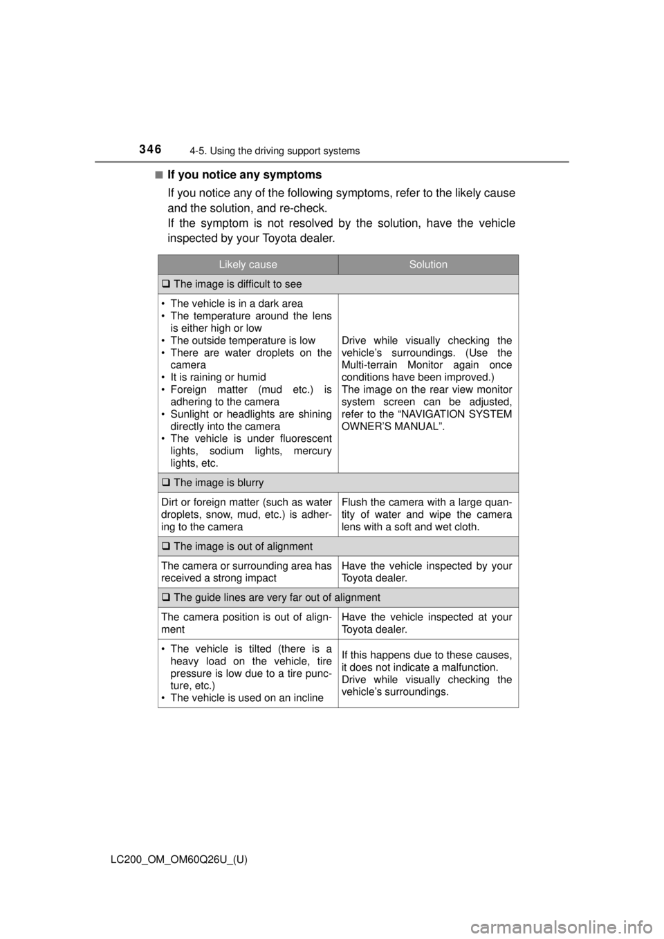
■If you notice any symptoms
If you notice any of the following symptoms, refer to the likely cause
and the solution, and re-check.
If the symptom is not resolved by the solution, have the vehicle
inspected by your Toyota dealer.
Likely causeSolution
The image is difficult to see
• The vehicle is in a dark area
• The temperature around the lens
is either high or low
• The outside temperature is low
• There are water droplets on the camera
• It is raining or humid
• Foreign matter (mud etc.) is adhering to the camera
• Sunlight or headlights are shining directly into the camera
• The vehicle is under fluorescent
lights, sodium lights, mercury
lights, etc.
Drive while visually checking the
vehicle’s surroundings. (Use the
Multi-terrain Monitor again once
conditions have been improved.)
The image on the rear view monitor
system screen can be adjusted,
refer to the “NAVIGATION SYSTEM
OWNER’S MANUAL”.
The image is blurry
Dirt or foreign matter (such as water
droplets, snow, mud, etc.) is adher-
ing to the cameraFlush the camera with a large quan-
tity of water and wipe the camera
lens with a soft and wet cloth.
The image is out of alignment
The camera or surrounding area has
received a strong impactHave the vehicle inspected by your
Toyota dealer.
The guide lines are very far out of alignment
The camera position is out of align-
mentHave the vehicle inspected at your
Toyota dealer.
• The vehicle is tilted (there is a
heavy load on the vehicle, tire
pressure is low due to a tire punc-
ture, etc.)
• The vehicle is used on an inclineIf this happens due to these causes,
it does not indicate a malfunction.
Drive while visually checking the
vehicle’s surroundings.
Page 347 of 620
LC200_OM_OM60Q26U_(U)
3474-5. Using the driving support systems
4
Driving
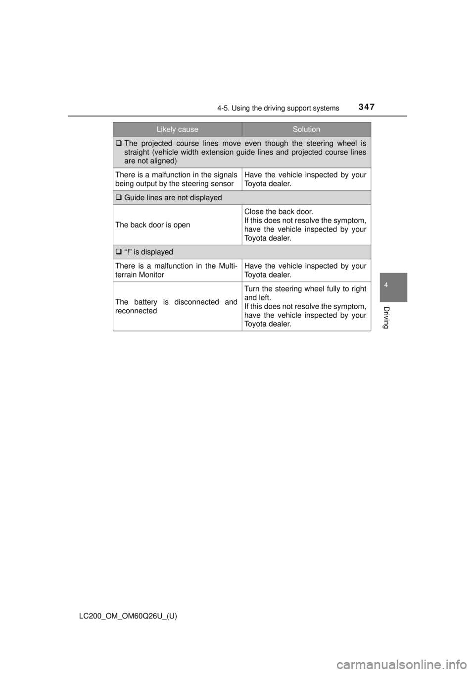
The projected course lines move even though the steering wheel is
straight (vehicle width extension guide lines and projected course lines
are not aligned)
There is a malfunction in the signals
being output by the steering sensorHave the vehicle inspected by your
Toyota dealer.
Guide lines are not displayed
The back door is open
Close the back door.
If this does not resolve the symptom,
have the vehicle inspected by your
Toyota dealer.
“!” is displayed
There is a malfunction in the Multi-
terrain MonitorHave the vehicle inspected by your
Toyota dealer.
The battery is disconnected and
reconnected
Turn the steering wheel fully to right
and left.
If this does not resolve the symptom,
have the vehicle inspected by your
Toyota dealer.
Likely causeSolution
Page 348 of 620
348
LC200_OM_OM60Q26U_(U)
4-5. Using the driving support systems
NOTICE
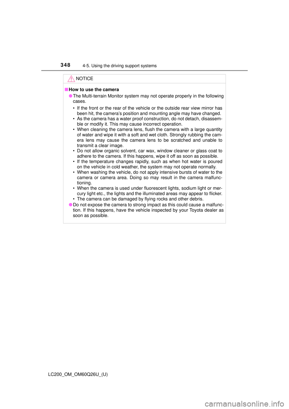
■How to use the camera
● The Multi-terrain Monitor system may not operate properly in the following
cases.
• If the front or the rear of the vehicl e or the outside rear view mirror has
been hit, the camera’s position and mounting angle may have changed.
• As the camera has a water proof construction, do not detach, disassem- ble or modify it. This may cause incorrect operation.
• When cleaning the camera lens, flush the camera with a large quantity of water and wipe it with a soft and wet cloth. Strongly rubbing the cam-
era lens may cause the camera lens to be scratched and unable to
transmit a clear image.
• Do not allow organic solvent, car wax, window cleaner or glass coat to adhere to the camera. If this happens, wipe it off as soon as possible.
• If the temperature changes rapidly, such as when hot water is poured on the vehicle in cold weather, the system may not operate normally.
• When washing the vehicle, do not apply intensive bursts of water to the
camera or camera area. Doing so may result in the camera malfunc-
tioning.
• When the camera is used under fluorescent lights, sodium light or mer-
cury light etc., the lights and the illuminated areas may appear to flic\
ker.
• The camera can be damaged by flying rocks and other debris.
● Do not expose the camera to strong impact as this could cause a malfunc-
tion. If this happens, have the vehicle inspected by your Toyota dealer as
soon as possible.
Page 349 of 620
349
LC200_OM_OM60Q26U_(U)
4-5. Using the driving support systems
4
Driving
BSM (Blind Spot Monitor)∗
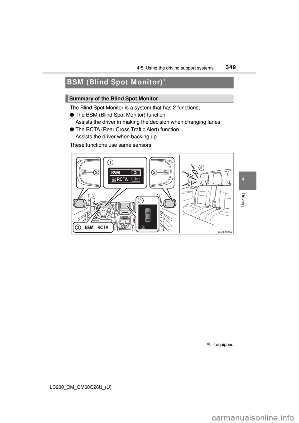
The Blind Spot Monitor is a system that has 2 functions;
● The BSM (Blind Spot Monitor) function
Assists the driver in making t he decision when changing lanes
● The RCTA (Rear Cross Traffic Alert) function
Assists the driver when backing up
These functions use same sensors.
∗: If equipped
Summary of the Blind Spot Monitor
Page 350 of 620
350
LC200_OM_OM60Q26U_(U)
4-5. Using the driving support systems
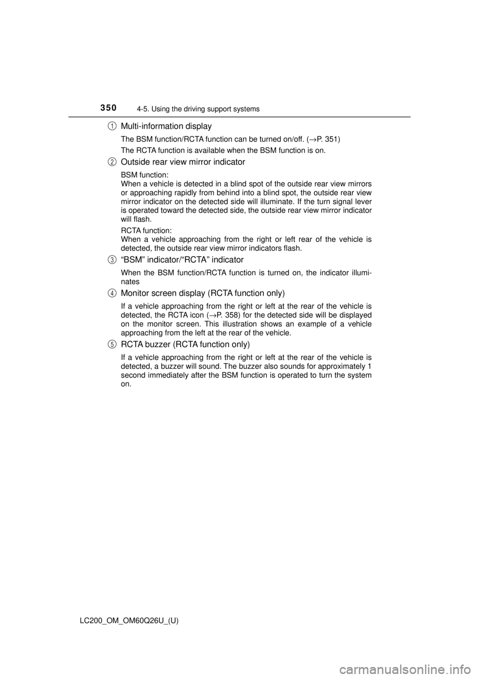
Multi-information display
The BSM function/RCTA function can be turned on/off. ( →P. 351)
The RCTA function is available when the BSM function is on.
Outside rear view mirror indicator
BSM function:
When a vehicle is detected in a blind spot of the outside rear view mirrors
or approaching rapidly from behind into a blind spot, the outside rear view
mirror indicator on the detected side will illuminate. If the turn signal lever
is operated toward the detected side, the outside rear view mirror indicator
will flash.
RCTA function:
When a vehicle approaching from the right or left rear of the vehicle is
detected, the outside rear view mirror indicators flash.
“BSM” indicator/“RCTA” indicator
When the BSM function/RCTA function is turned on, the indicator illumi-
nates
Monitor screen display (RCTA function only)
If a vehicle approaching from the right or left at the rear of the vehic\
le is
detected, the RCTA icon ( →P. 358) for the detected side will be displayed
on the monitor screen. This illustration shows an example of a vehicle
approaching from the left at the rear of the vehicle.
RCTA buzzer (RCTA function only)
If a vehicle approaching from the right or left at the rear of the vehic\
le is
detected, a buzzer will sound. The buzzer also sounds for approximately 1
second immediately after the BSM function is operated to turn the system
on.
1
2
3
4
5