fuel cap TOYOTA MIRAI 2022 User Guide
[x] Cancel search | Manufacturer: TOYOTA, Model Year: 2022, Model line: MIRAI, Model: TOYOTA MIRAI 2022Pages: 556, PDF Size: 17.34 MB
Page 335 of 556
3356-1. Using the air conditioning system and defogger
Owners Manual_USA_M62084_en
6
Interior features
mirror defoggers switch.
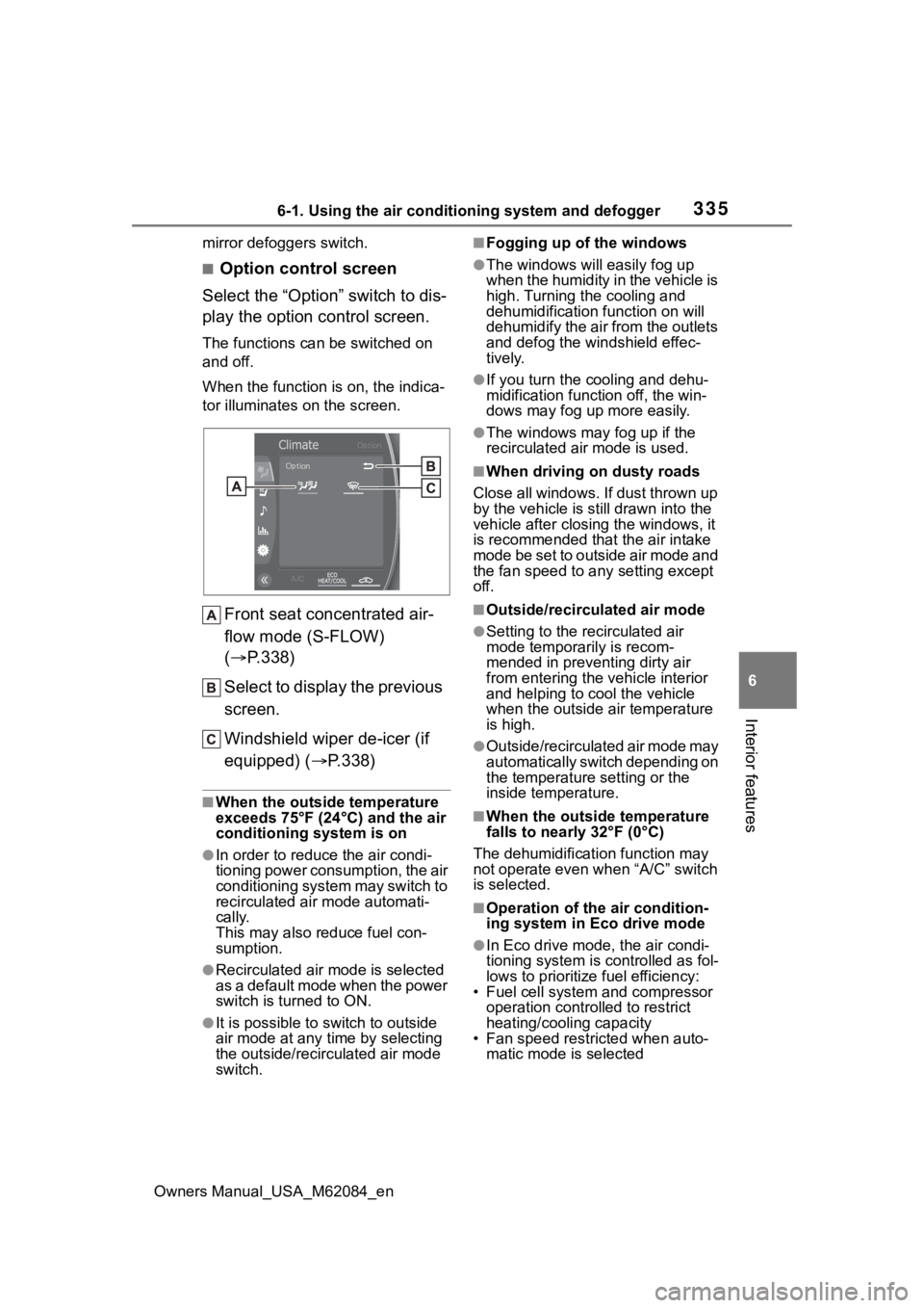
■Option control screen
Select the “Option” switch to dis-
play the option control screen.
The functions can be switched on
and off.
When the function i s on, the indica-
tor illuminates on the screen.
Front seat concentrated air-
flow mode (S-FLOW)
( P.338)
Select to display the previous
screen.
Windshield wiper de-icer (if
equipped) ( P.338)
■When the outside temperature
exceeds 75°F (24°C) and the air
conditioning system is on
●In order to reduce the air condi-
tioning power consumption, the air
conditioning system may switch to
recirculated air mode automati-
cally.
This may also reduce fuel con-
sumption.
●Recirculated air mode is selected
as a default mode when the power
switch is turned to ON.
●It is possible to switch to outside
air mode at any time by selecting
the outside/recirculated air mode
switch.
■Fogging up of the windows
●The windows will easily fog up
when the humidity in the vehicle is
high. Turning the cooling and
dehumidification function on will
dehumidify the air from the outlets
and defog the windshield effec-
tively.
●If you turn the cooling and dehu-
midification function off, the win-
dows may fog up more easily.
●The windows may fog up if the
recirculated air mode is used.
■When driving on dusty roads
Close all windows. If dust thrown up
by the vehicle is still drawn into the
vehicle after closing the windows, it
is recommended that the air intake
mode be set to outside air mode and
the fan speed to a ny setting except
off.
■Outside/recirculated air mode
●Setting to the recirculated air
mode temporarily is recom-
mended in preventing dirty air
from entering the vehicle interior
and helping to c ool the vehicle
when the outside air temperature
is high.
●Outside/recirculated air mode may
automatically switch depending on
the temperature setting or the
inside temperature.
■When the outside temperature
falls to nearly 32°F (0°C)
The dehumidification function may
not operate even when “A/C” switch
is selected.
■Operation of the air condition-
ing system in Eco drive mode
●In Eco drive mode, the air condi-
tioning system is controlled as fol-
lows to prioritize fuel efficiency:
• Fuel cell system and compressor
operation controlled to restrict
heating/cooling capacity
• Fan speed restri cted when auto-
matic mode is selected
Page 383 of 556
3837-1. Maintenance and care
Owners Manual_USA_M62084_en
7
Maintenance and care
NOTICE
■Cleaning the exterior lights
●Wash carefully. Do not use
organic substances or scrub
with a hard brush.
This may damage the surfaces
of the lights.
●Do not apply wax to the sur-
faces of the lights.
Wax may cause damage to the
lenses.
■When washing the car
Do not remove the vehicle recep-
tacle cap and directly pour water
over the vehicle receptacle. If
water enters the vehicle recepta-
cle, damage may occur.
■When using an automatic car
wash
Set the wiper switch to the off
position.
If the wiper switch is in “AUTO”,
the wipers may operate and the
wiper blades may be damaged.
■When using a high pressure
car wash
●When washing the vehicle, do
not spray the came ra or its sur-
rounding area directly with a
high pressure washer. Shock
applied from high pressure
water may cause the device to
not operate normally.
●Do not spray water directly on
the radar sensor which is
equipped behind the emblem.
Otherwise it may cause the
device to be damaged.
●Do not bring the nozzle tip close
to boots (rubber or resin manu-
factured cover), connectors or
the following parts. The parts
may be damaged if they come
into contact with high-pressure
water.
• Fuel cell stack
• Traction related parts
• Steering parts
• Suspension parts
• Brake parts
●Keep the cleaning nozzle at
least 11.9 in. (30 cm) away from
the vehicle body. Otherwise
resin section, s uch as moldings
and bumpers, may be deformed
and damaged.
Also, do not continuously hold the
nozzle in the same place.
●Do not spray the lower part of
the windshield continuously.
If water enters the air conditioning
system intake located near the
lower part of the windshield, the
air conditioning system may not
operate correctly.
●Do not wash the underside of
the vehicle using a high pres-
sure car washer.
Page 397 of 556

3977-3. Do-it-yourself maintenance
Owners Manual_USA_M62084_en
7
Maintenance and care
■Installing the fuel cell stack
cover
Install the fuel cell stack cover.
1 Attach the hooks on the rear
side of the fuel cell stack
cover.
2 Insert the front side of the
fuel cell stack cover on the
pins.
The coolant level is satisfactory
if it is between the “MAX” and
“MIN” lines on the reservoir when the fuel cell system is
cold.
Fuel cell stack reservoir cap
“MAX” line
“MIN” line
If the level is on or below the “MIN”
line, add coolant up to the “MAX”
line. ( P.476)
The coolant level is satisfactory
if it is between the “MAX” and
“MIN” lines on the reservoir
when the fuel cell system is
cold.
NOTICE
■Checking the fuel cell stack
cover after installation
Make sure that the cover is
securely installed in its original
position.
Checking the fuel cell
stack coolant
NOTICE
■Fuel cell stack coolant
An exclusive coola nt for the fuel
cell system is filled in the fuel cell
stack coolant reservoir. Do not
use any substitute. It may dam-
age your vehicle.
Checking the inverter
coolant
Page 398 of 556

3987-3. Do-it-yourself maintenance
Owners Manual_USA_M62084_en
Inverter coolant reservoir cap
“MAX” line
“MIN” line
If the level is on or below the “MIN”
line, add coolant up to the “MAX”
line. (P.476)
■Inverter coolant selection
Only use “Toyota Super Long Life
Coolant” or a similar high quality
ethylene glycol based non-silicate,
non-amine, non-nitrite, and non-
borate coolant with long-life hybrid
organic acid technology.
U.S.A.:
“Toyota Super Long Life Coolant” is
a mixture of 50% coolant and 50%
deionized water. (Minimum tem-
perature: -31°F [-35°C])
Canada:
“Toyota Super Long Life Coolant” is
a mixture of 55% coolant and 45%
deionized water. (Minimum tem-
perature: -44°F [-42°C])
For more details about coolant, con-
tact your Toyota dealer.
■If the inverter coolant level
drops within a short time of
replenishing
Visually check the radiators, hoses,
inverter coolant reservoir cap, drain
cock and water pump.
If you cannot find a leak, have your
Toyota dealer test the cap and
check for leaks in the cooling sys- tem.
Check the radiator and con-
denser and clear away any for-
eign objects. If either of the
above parts is extremely dirty or
you are not sure of their condi-
tion, have your vehicle
inspected by your Toyota dealer.
WARNING
■When the cell system is hot
Do not remove the coolant reser-
voir caps. ( P.479)
The cooling system may be under
pressure and may spray hot cool-
ant if the cap is removed, causing
serious injuries, such as burns.
NOTICE
■When adding coolant
Coolant is neither plain water nor
straight antifreeze. The correct
mixture of water and antifreeze
must be used to provide proper
lubrication, corrosion protection
and cooling. Be sure to read the
antifreeze or coolant label.
■If you spill coolant
Be sure to wash it off with water to
prevent it from damaging parts or
paint.
Checking the radiator and
condenser
WARNING
■When the fuel cell system is
hot
Do not touch the radiator or con-
denser as they may be hot and
cause serious injuries, such as
burns.
Page 407 of 556
4077-3. Do-it-yourself maintenance
Owners Manual_USA_M62084_en
7
Maintenance and care
■The tire pressure warning
system must be initialized
in the following circum-
stances:
When the tire inflation pres-
sure is changed such as
when changing traveling
speed or load weight.
When the tire inflation pres-
sure is changed such as
when the tire size is changed.
When rotating the tires.
After performing the transmit-
ter ID code registration proce-
dure. ( P.409) When the tire pressure warning
system is initialized, the current
tire inflation pressure is set as
the benchmark pressure.
■How to initialize the tire
pressure warning system
1 Park the vehicle in a safe
place, turn the power switch
off and wait 20 minutes or
more.
Initialization cannot be performed
while the vehicle is moving.
2Adjust the tire inflation pres-
sure to the specified cold tire
inflation pressure level.
Make sure to adjust the tire pres-
sure to the specifie d cold tire infla-
tion pressure level. The tire
pressure warning system will oper-
ate based on this pressure level.
3Start the fuel cell system.
4 Press or of the meter
control switch to select .
5 Press or to select
“Vehicle Settings” and then
press and hold .
6 Press or to select
“TPWS” and then press .
7 Press or to select “Set
Pressure”. Then press and
hold until the tire pressure
warning light starts blinking.
A message is displayed on the
multi-information di splay. Also, “--”
is displayed for inflation pressure of
NOTICE
■Repairing or replacing tires,
wheels, tire pressure warn-
ing valves, transmitters and
tire valve caps
●When removing or fitting the
wheels, tires or the tire pressure
warning valves and transmit-
ters, contact your Toyota dealer
as the tire pr essure warning
valves and transmitters may be
damaged if not handled cor-
rectly.
●Make sure to install the tire
valve caps. If the tire valve caps
are not installed, water could
enter the tire pressure warning
valves, corrode the valve, and
cause sticking and air leaks.
●When replacing ti re valve caps,
do not use tire valve caps other
than those specified. The cap
may become stuck.
Initializing the tire pres-
sure warning system
Page 416 of 556

4167-3. Do-it-yourself maintenance
Owners Manual_USA_M62084_en
Tire pressure gauge
1 Remove the tire valve cap.
2 Press the tip of the tire pres-
sure gauge onto the tire
valve.
3 Read the pressure using the
gauge gradations.
4 If the tire inflation pressure is
not at the recommended
level, adjust the pressure.
If you add too much air, press
the center of the valve to
deflate.
5 After completing the tire infla-
tion pressure measurement
and adjustment, apply soapy
water to the valve and check
for leakage.
6 Put the tire valve cap back
on.
■Tire inflation pressure check
interval
You should check tire inflation pres-
sure every two weeks, or at least
once a month. Do not forget to
check the spare.
■Effects of incorrect tire inflation
pressure
Driving with incorrect tire inflation
pressure may result in the following:
●Reduced fuel economy
●Reduced driving comfort and poor
handling
●Reduced tire life due to wear
●Reduced safety
●Damage to the drive train
If a tire needs frequent inflating,
have it checked by your Toyota
dealer.
■Instructions for checking tire
inflation pressure
When checking tire inflation pres-
sure, observe the following:
●Check only when the tires are
cold.
If your vehicle has been parked for
at least 3 hours or has not been
driven for more than 1 mile or 1.5
km, you will get an accurate cold
tire inflation pressure reading.
●Always use a tire pressure gauge.
It is difficult to j udge if a tire is
properly inflated based only on its
appearance.
●It is normal for the tire inflation
pressure to be higher after driving
as heat is generated in the tire. Do
not reduce tire inflation pressure
after driving.
●Never exceed the vehicle capacity
weight.
Passengers and luggage weight
should be placed so that the vehi-
cle is balanced.
WARNING
■Proper inflation is critical to
save tire performance
Keep your tires properly inflated.
If the tires are not properly
inflated, the following conditions
may occur which could lead to an
accident resulting in death or seri-
ous injury:
●Excessive wear
●Uneven wear
●Poor handling
●Possibility of blowouts resulting
from overheated tires
●Air leaking from between tire
and wheel
●Wheel deformation and/or tire
damage
Page 433 of 556

4338-1. Essential information
Owners Manual_USA_M62084_en
8
When trouble arises
briefly 3 times or more in suc-
cession.
5 Stop the vehicle in a safe
place by the road.
If the door can be opened,
open the door and exit the
vehicle.
If the door can not be opened,
open the window using the
power window switch and
ensure an escape route.
If the window can be opened,
exit the vehicle through the
window.
If the door and window cannot
be opened due to the rising
water, remain calm, wait until
the water level inside the
vehicle rises to the point that
the water pressure inside of
the vehicle equals the water
pressure outside of the vehi-
cle and then open the door
after waiting for the rising
water to enter the vehicle, and
exit the vehicle. When the
WARNING
■If the fuel cell system has to
be turned off while driving
Power assist for the steering
wheel will be lost, making the
steering wheel heavier to turn.
Decelerate as much as possible
before turning off the fuel cell sys-
tem.
If the vehicle is sub-
merged or water on
the road is rising
This vehicle is not designed
to be able to drive on roads
that are deeply flooded with
water. Do not drive on roads
where the roads may be
submerged or the water
may be rising. It is danger-
ous to remain in the vehicle,
if it anticipated that the vehi-
cle will be flooded or set a
drift. Remain calm and fol-
low the following.
Page 474 of 556
4748-2. Steps to take in an emergency
Owners Manual_USA_M62084_en
●Use a 12-volt battery with the
same case size as the previous
12-volt battery and an equivalent
20 hour rate capacity (20HR) or
greater.
• If the sizes differ, the 12-volt bat-
tery cannot be properly secured.
• If the 20 hour rate capacity is low,
even if the time period where the
vehicle is not used is a short time,
the 12-volt battery may discharge
and the fuel cell system may not
be able to start.
●Use a 12-volt battery with a han-
dle. If a 12-volt b attery without a
handle is used, removal is more
difficult.
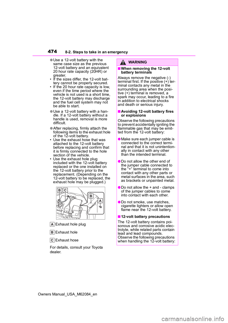
●After replacing, firmly attach the
following items to the exhaust hole
of the 12-volt battery.
• Use the exhaust hose that was attached to the 12-volt battery
before replacing an d confirm that
it is firmly connected to the hole
section of t he vehicle.
• Use the exhaust hole plug included with the 12-volt battery
replaced or the one installed on
the 12-volt battery prior to the
replacement. (Depending on the
12-volt battery to be replaced, the
exhaust hole may be plugged.)
Exhaust hole plug
Exhaust hole
Exhaust hose
For details, consult your Toyota
dealer.
WARNING
■When removing the 12-volt
battery terminals
Always remove the negative (-)
terminal first. If the positive (+) ter-
minal contacts any metal in the
surrounding area when the posi-
tive (+) terminal is removed, a
spark may occur, leading to a fire
in addition to ele ctrical shocks
and death or serious injury.
■Avoiding 12-volt battery fires
or explosions
Observe the following precautions
to prevent accidentally igniting the
flammable gas that may be emit-
ted from the 12-volt battery:
●Make sure each jumper cable is
connected to the correct termi-
nal and that it is not unintention-
ally in contact with any other
than the intended terminal.
●Do not allow the other end of
the jumper cable connected to
the “+” terminal to come into
contact with any other parts or
metal surfaces in the area, such
as brackets or unpainted metal.
●Do not allow the + and - clamps
of the jumper cables to come
into contact with each other.
●Do not smoke, use matches,
cigarette lighter s or allow open
flame near the 1 2-volt battery.
■12-volt battery precautions
The 12-volt battery contains poi-
sonous and corrosive acidic elec-
trolyte, while related parts contain
lead and lead compounds.
Observe the following precautions
when handling the 12-volt battery:
Page 479 of 556
4798-2. Steps to take in an emergency
Owners Manual_USA_M62084_en
8
When trouble arises
able.
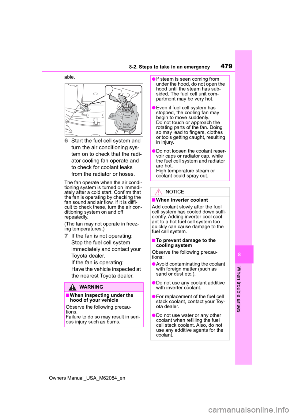
6 Start the fuel cell system and
turn the air conditioning sys-
tem on to check that the radi-
ator cooling fan operate and
to check for coolant leaks
from the radiator or hoses.
The fan operate when the air condi-
tioning system is turned on immedi-
ately after a cold s tart. Confirm that
the fan is operating by checking the
fan sound and air flow. If it is diffi-
cult to check these, turn the air con-
ditioning system on and off
repeatedly.
(The fan may not o perate in freez-
ing temperatures.)
7 If the fan is not operating:
Stop the fuel cell system
immediately and contact your
Toyota dealer.
If the fan is operating:
Have the vehicle inspected at
the nearest Toyota dealer.
WARNING
■When inspecting under the
hood of your vehicle
Observe the following precau-
tions.
Failure to do so may result in seri-
ous injury such as burns.
●If steam is seen coming from
under the hood, do not open the
hood until the steam has sub-
sided. The fuel cell unit com-
partment may be very hot.
●Even if fuel cell system has
stopped, the cooling fan may
begin to move suddenly.
Do not touch or approach the
rotating parts of the fan. Doing
so may lead to fingers, clothes
or tools getting caught, resulting
in injury.
●Do not loosen the coolant reser-
voir caps or radia tor cap, while
the fuel cell system and radiator
are hot.
High temperature steam or
coolant could spray out.
NOTICE
■When inverter coolant
Add coolant slowly after the fuel
cell system has cooled down suffi-
ciently. Adding inverter cool cool-
ant to a hot fuel cell system too
quickly can cause damage to the
fuel cell system.
■To prevent damage to the
cooling system
Observe the following precau-
tions:
●Avoid contaminating the coolant
with foreign matter (such as
sand or dust etc.).
●Do not use any coolant additive
with inverter coolant.
●For replacement of the fuel cell
stack coolant, contact your Toy-
ota dealer.
●Do not use water or any other
coolant when refilling the fuel
cell stack coolant. Also, do not
use any additive agents for the
coolant.
Page 482 of 556

4829-1. Specifications
Owners Manual_USA_M62084_en
9-1.Specifications
*1: Unladen vehicles
*2: Vehicles without electronic sunshade
*3: Vehicles with electronic sunshade
■Vehicle identification num-
ber
The vehicle identification num-
ber (VIN) is the legal identifier
for your vehicle. This is the pri-
mary identification number for
your Toyota. It is used in regis-
tering the ownership of your
vehicle.
This number is stamped on the
top left of the instrument panel. This number is also stamped
under the right-hand front seat.
Maintenance data (fuel,
fluid level, etc.)
Dimensions and weight
Overall length195.9 in. (4975 mm)
Overall width74.2 in. (1885 mm)
Overall height*157.9 in. (1470 mm)*2
58.3 in. (1480 mm)*3
Wheelbase115.0 in. (2920 mm)
Tread*1Front63.4 in. (1610 mm)
Rear63.2 in. (1605 mm)
Vehicle capacity weight
(Occupants + luggage)835 lb. (380 kg)
Seating capacity
Seating capacity5 (Front 2, Rear 3)
Vehicle identification