display TOYOTA MIRAI 2022 Owners Manual
[x] Cancel search | Manufacturer: TOYOTA, Model Year: 2022, Model line: MIRAI, Model: TOYOTA MIRAI 2022Pages: 556, PDF Size: 17.34 MB
Page 1 of 556
1
2
3
4
5
6
7
8
9
10
Owners Manual_USA_M62084_en
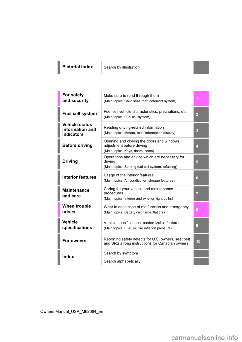
Pictorial indexSearch by illustration
For safety
and securityMake sure to read through them
(Main topics: Child seat, theft deterrent system)
Fuel cell systemFuel cell vehicle characteristics, precautions, etc.
(Main topics: Fuel cell system)
Vehicle status
information and
indicatorsReading driving-related information
(Main topics: Meters, multi-information display)
Before driving
Opening and closing the doors and windows,
adjustment before driving
(Main topics: Keys, doors, seats)
Driving
Operations and advice which are necessary for
driving
(Main topics: Starting f uel cell system, refueling)
Interior featuresUsage of the interior features
(Main topics: Air conditioner, storage features)
Maintenance
and careCaring for your vehicle and maintenance
procedures
(Main topics: Interior and exterior, light bulbs)
When trouble
arisesWhat to do in case of malfunction and emergency
(Main topics: Battery discharge, flat tire)
Vehicle
specificationsVehicle specifications, customizable features
(Main topics: Fuel, oil, tire inflation pressure)
For ownersReporting safety defects for U.S. owners, seat belt
and SRS airbag instructions for Canadian owners
IndexSearch by symptom
Search alphabetically
Page 2 of 556
2
Owners Manual_USA_M62084_enTABLE OF CONTENTS
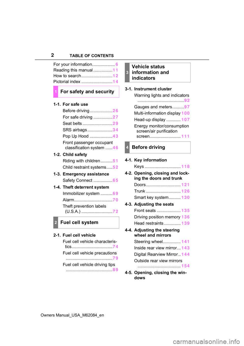
For your information...................
6
Reading this manual ................ 11
How to search .......................... 12
Pictorial index .......................... 14
1-1. For safe use Before driving ................... 26
For safe driving ................ 27
Seat belts ......................... 29
SRS airbags ..................... 34
Pop Up Hood ................... 43
Front passenger occupant classification system ...... 46
1-2. Child safety Riding with children .......... 51
Child restraint systems..... 52
1-3. Emergency assistance Safety Connect ................ 65
1-4. Theft deterrent system Immobilizer system .......... 69
Alarm................................ 70
Theft prevention labels (U.S.A.) .......................... 72
2-1. Fuel cell vehicle Fuel cell vehicle characteris-tics .................................. 74
Fuel cell vehicle precautions ....................................... 79
Fuel cell vehicle driving tips ....................................... 893-1. Instrument cluster
Warning lights and indicators....................................... 92
Gauges and meters .......... 97
Multi-information display 100
Head-up display ............ 107
Energy monitor/ consumption
screen/air purification
screen.......................... 111
4-1. Key information Keys .............................. 118
4-2. Opening, closing and lock- ing the doors and trunk
Doors ............................. 121
Trunk ............................. 126
Smart key system .......... 130
4-3. Adjusting the seats Front seats .................... 135
Driving position memory 136
Head restraints .............. 139
4-4. Adjusting the steering wheel and mirrors
Steering wheel............... 141
Inside rear view mirror ... 143
Digital Rearview Mirror .. 144
Outside rear view mirrors .................................... 154
4-5. Opening, closing the win- dows
1For safety and security
2Fuel cell system
3
Vehicle status
information and
indicators
4Before driving
Page 4 of 556
4TABLE OF CONTENTS
Owners Manual_USA_M62084_en
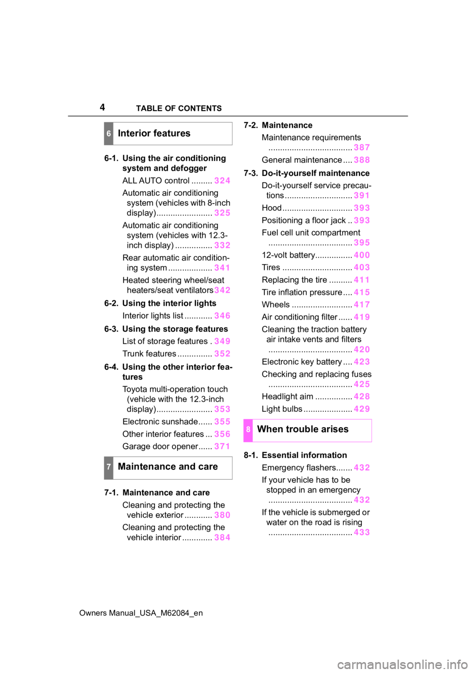
6-1. Using the air conditioning
system and defogger
ALL AUTO control ......... 324
Automatic air conditioning system (vehicles with 8-inch
display) ........................ 325
Automatic air conditioning system (vehicles with 12.3-
inch display) ................ 332
Rear automatic air condition- ing system ................... 341
Heated steering wheel/seat heaters/seat ventilators 342
6-2. Using the interior lights Interior lights list ............ 346
6-3. Using the storage features List of storage features . 349
Trunk features ............... 352
6-4. Using the other interior fea- tures
Toyota multi-operation touch
(vehicle with the 12.3-inch
display) ........................ 353
Electronic sunshade...... 355
Other interior features ... 356
Garage door opener...... 371
7-1. Maintenance and care Cleaning and protecting the vehicle exterior ............ 380
Cleaning and protecting the vehicle interior ............. 3847-2. Maintenance
Maintenance requirements.................................... 387
General maintenance .... 388
7-3. Do-it-yourself maintenance Do-it-yourself service precau-tions ............................. 391
Hood .............................. 393
Positioning a floor jack .. 393
Fuel cell unit compartment .................................... 395
12-volt battery................ 400
Tires .............................. 403
Replacing the tire .......... 411
Tire inflation pressure .... 415
Wheels .......................... 417
Air conditioning filter ...... 419
Cleaning the traction battery air intake vents and filters
.................................... 420
Electronic key battery .... 423
Checking and replacing fuses .................................... 425
Headlight aim ................ 428
Light bulbs ..................... 429
8-1. Essential information Emergency flashers....... 432
If your vehicle has to be stopped in an emergency.................................... 432
If the vehicle is submerged or water on the road is rising.................................... 433
6Interior features
7Maintenance and care
8When trouble arises
Page 17 of 556
17Pictorial index
Owners Manual_USA_M62084_en
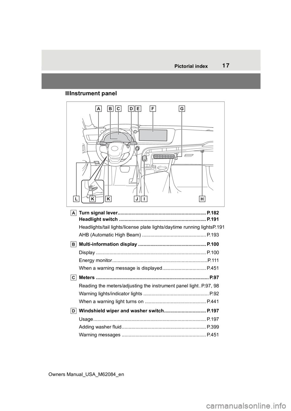
■ Instrument panel
Turn signal lever.............................................. ................... P.182
Headlight switch ............................................... ................. P.191
Headlights/tail lights/license pla te lights/daytime running lightsP.191
AHB (Automatic High Beam) ............................................... P.193
Multi-information display . ................................................. P.100
Display ........................................................ ......................... P.100
Energy monitor................................................. .....................P.111
When a warning message is displayed ............................ .... P.451
Meters ......................................................... .......................... P.97
Reading the meters/adjusting the instrument panel light . P.97, 9 8
Warning lights/indicator lights ................................ ................ P.92
When a warning light turns on .................................. ........... P.441
Windshield wiper and washer switch............................... P.197
Usage................................................................................... P.197
Adding washer fluid .............................................................. P.399
Warning messages ............................................... ............... P.451
Page 19 of 556
19Pictorial index
Owners Manual_USA_M62084_en
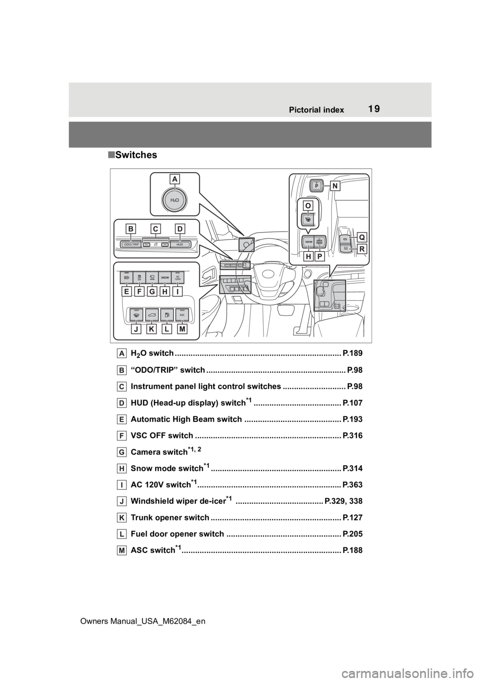
■ Switches
H2O switch ....................................................... ................... P.189
“ODO/TRIP” switch .............................................. ................ P.98
Instrument panel light control switches ........................ .... P.98
HUD (Head-up display) switch
*1....................................... P.107
Automatic High Beam switch ..................................... ...... P.193
VSC OFF switch ................................................. ................ P.316
Camera switch
*1, 2
Snow mode switch*1.......................................................... P.314
AC 120V switch
*1............................................................... .P.363
Windshield wiper de-icer
*1 ....................................... P.329, 338
Trunk opener switch ............................................ .............. P.127
Fuel door opener switch ........................................ ........... P.205
ASC switch
*1............................................................... ........ P.188
Page 60 of 556
601-2. Child safety
Owners Manual_USA_M62084_en
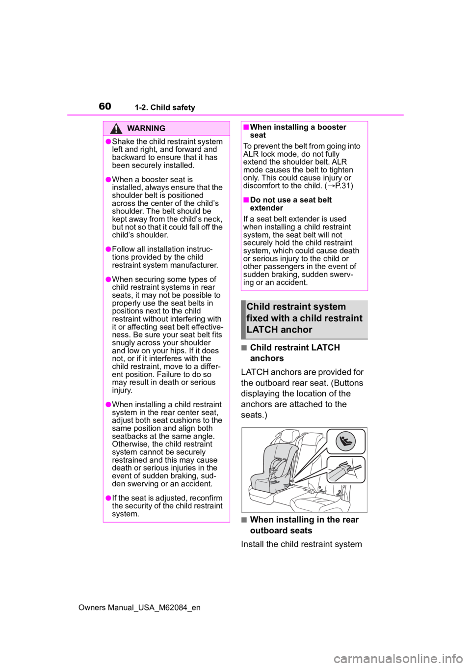
■Child restraint LATCH
anchors
LATCH anchors are provided for
the outboard rear seat. (Buttons
displaying the location of the
anchors are attached to the
seats.)
■When installing in the rear
outboard seats
Install the child restraint system
WARNING
●Shake the child restraint system
left and right, and forward and
backward to ensure that it has
been securely installed.
●When a booster seat is
installed, always ensure that the
shoulder belt is positioned
across the center of the child’s
shoulder. The belt should be
kept away from the child’s neck,
but not so that it could fall off the
child’s shoulder.
●Follow all installation instruc-
tions provided by the child
restraint system manufacturer.
●When securing some types of
child restraint s ystems in rear
seats, it may not be possible to
properly use the seat belts in
positions next to the child
restraint without interfering with
it or affecting seat belt effective-
ness. Be sure your seat belt fits
snugly across your shoulder
and low on your hips. If it does
not, or if it interferes with the
child restraint, move to a differ-
ent position. Failure to do so
may result in death or serious
injury.
●When installing a child restraint
system in the rear center seat,
adjust both seat cushions to the
same position and align both
seatbacks at the same angle.
Otherwise, the child restraint
system cannot be securely
restrained and t his may cause
death or serious injuries in the
event of sudden braking, sud-
den swerving or an accident.
●If the seat is adjusted, reconfirm
the security of the child restraint
system.
■When installing a booster
seat
To prevent the belt from going into
ALR lock mode, do not fully
extend the shoulder belt. ALR
mode causes the belt to tighten
only. This could cause injury or
discomfort to the child. ( P. 3 1 )
■Do not use a seat belt
extender
If a seat belt extender is used
when installing a child restraint
system, the seat belt will not
securely hold the child restraint
system, which could cause death
or serious injury to the child or
other passengers in the event of
sudden braking, sudden swerv-
ing or an accident.
Child restraint system
fixed with a child restraint
LATCH anchor
Page 77 of 556
772-1. Fuel cell vehicle
Owners Manual_USA_M62084_en
2
Fuel cell system
in order to warn people nearby
of the vehicle’s approach. The
sound will stop when the vehicle
speed exceeds approximately
23 mph (37 km/h).
■How to hear the warning
In the following ca ses, the acoustic
vehicle alerting system may be diffi-
cult for surrounding people to hear.
●In very noisy areas
●In the wind or the rain
Also, as the acoustic vehicle alerting
system is installed on the front of the
vehicle, it may be m ore difficult to
hear from the rear of the vehicle
compared to the front.
*: This function can only be used in
the mainland U.S.A. It cannot be
used in other states and territo-
ries, including Alaska and Hawaii.
This system operates based on
the driving situation to enhance
fuel economy. For details about
Predictive efficient drive, refer to
“NAVIGATION AND MULTIME-
DIA SYSTEM OWNER’S MAN-
UAL”.
■Predictive deceleration sup-
port
When the vehicle approaches
to predictive deceleration sup-
port points registered in the
navigation system, the refer-
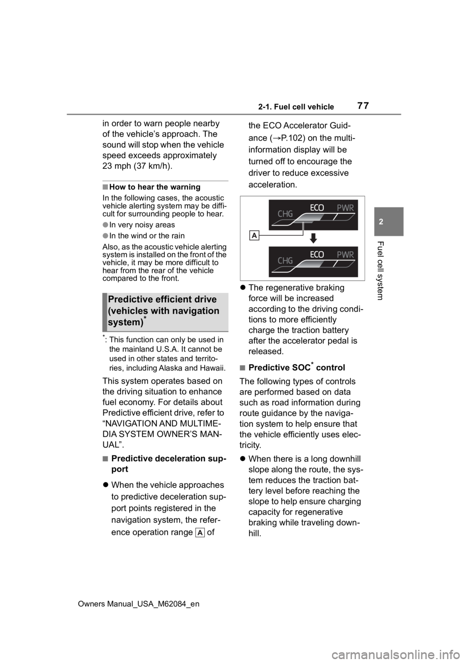
ence operation range of the ECO Accelerator Guid-
ance (
P.102) on the multi-
information display will be
turned off to encourage the
driver to reduce excessive
acceleration.
The regenerative braking
force will be increased
according to the driving condi-
tions to more efficiently
charge the traction battery
after the accelerator pedal is
released.
■Predictive SOC* control
The following types of controls
are performed based on data
such as road information during
route guidance by the naviga-
tion system to help ensure that
the vehicle effici ently uses elec-
tricity.
When there is a long downhill
slope along the route, the sys-
tem reduces the traction bat-
tery level before reaching the
slope to help ensure charging
capacity for regenerative
braking while traveling down-
hill.
Predictive efficient drive
(vehicles with navigation
system)
*
Page 81 of 556
812-1. Fuel cell vehicle
Owners Manual_USA_M62084_en
2
Fuel cell system
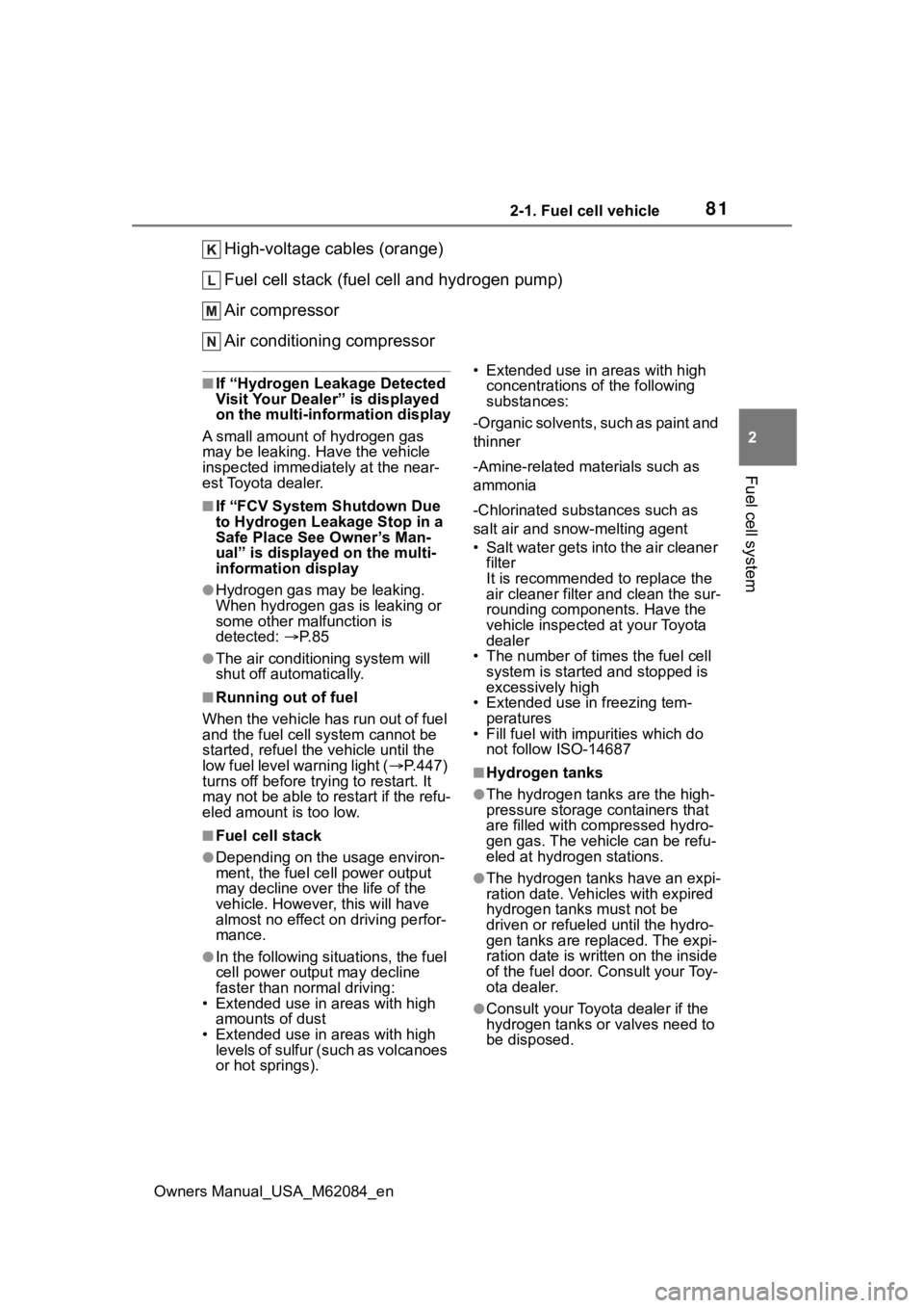
High-voltage cables (orange)
Fuel cell stack (fuel cell and hydrogen pump)
Air compressor
Air conditioning compressor
■If “Hydrogen Leakage Detected
Visit Your Dealer” is displayed
on the multi-information display
A small amount of hydrogen gas
may be leaking. Have the vehicle
inspected immediately at the near-
est Toyota dealer.
■If “FCV System Shutdown Due
to Hydrogen Leakage Stop in a
Safe Place See Owner’s Man-
ual” is displayed on the multi-
information display
●Hydrogen gas may be leaking.
When hydrogen gas is leaking or
some other malfunction is
detected: P. 8 5
●The air conditioning system will
shut off automatically.
■Running out of fuel
When the vehicle has run out of fuel
and the fuel cell system cannot be
started, refuel the vehicle until the
low fuel level warning light ( P.447)
turns off before try ing to restart. It
may not be able to restart if the refu-
eled amount is too low.
■Fuel cell stack
●Depending on the usage environ-
ment, the fuel ce ll power output
may decline over the life of the
vehicle. However, this will have
almost no effect on driving perfor-
mance.
●In the following situations, the fuel
cell power output may decline
faster than normal driving:
• Extended use in areas with high amounts of dust
• Extended use in areas with high levels of sulfur (such as volcanoes
or hot springs). • Extended use in areas with high
concentrations o f the following
substances:
-Organic solvents, such as paint and
thinner
-Amine-related materials such as
ammonia
-Chlorinated substances such as
salt air and snow-melting agent
• Salt water gets into the air cleaner filter
It is recommended to replace the
air cleaner filter and clean the sur-
rounding components. Have the
vehicle inspected at your Toyota
dealer
• The number of times the fuel cell system is started and stopped is
excessively high
• Extended use in freezing tem- peratures
• Fill fuel with impurities which do not follow ISO-14687
■Hydrogen tanks
●The hydrogen tanks are the high-
pressure storage containers that
are filled with co mpressed hydro-
gen gas. The vehicle can be refu-
eled at hydrogen stations.
●The hydrogen tanks have an expi-
ration date. Vehicles with expired
hydrogen tanks must not be
driven or refueled until the hydro-
gen tanks are replaced. The expi-
ration date is written on the inside
of the fuel door. Consult your Toy-
ota dealer.
●Consult your Toyota dealer if the
hydrogen tanks or valves need to
be disposed.
Page 82 of 556

822-1. Fuel cell vehicle
Owners Manual_USA_M62084_en
■Fuel cell stack coolant
●Fuel cell stack coolant uses a spe-
cifically-designed fluid with high
electrical insulation properties, in
order to safely cool the high-volt-
age fuel cell stack.
●Never add water or other coolants
to the fuel cell stack cooling sys-
tem, as they will cause permanent
damage.
●Consult your Toyota dealer for
replenishing or changing the fuel
cell stack coolant.
■Ion filter
●An ion filter is inst alled in the cool-
ant lines for the fuel cell stack, in
order to maintain the normal insu-
lation properties of the coolant.
●It is necessary to periodically
change the ion filter. ( P.454)
Contact your Toyota dealer for this
periodic maintenance.
■Tailpipe
●When the power switch is turned
off and the fuel cell system is
stopped ( P.174) after driving,
exhaust water is discharged. Be
careful when standing behind the
vehicle to avoid dripping or spray-
ing.
●It is possible to manually purge
the exhaust. Thi s may be desir-
able, for instance, before parking
in a garage. This is done by press-
ing the H
2O switch. ( P.189)
●On cold days, water vapor in the
exhaust may appe ar as a white
mist emitted from the tailpipe. This
is not a malfunction. A white mist
may be emitted from the vehicle
side depending on the wind direc-
tion. If it is a concern, consult with
a Toyota dealer.
●If the tailpipe is blocked, the fuel
cell system will stop.
●In the following state when cold, a
white mist may be emitted. Water
vapor is being emitted as a sys-
tem protection and it is not a mal- function.
• If several minutes have passed after opening the fuel lid, such as
refueling.
• Several hours have passed after the power switch was turned off.
■Hydrogen detectors
When the power switch is turned to
ON, the hydrogen detectors are
activated.
■Power output restriction
When the power output is restricted,
the vehicle may fa il to accelerate or
even decelerate, even though the
accelerator pedal is depressed. If a
safe driving speed cannot be main-
tained, stop the ve hicle in a safe
place away from the traffic. This
may be caused by the following con-
ditions:
●The coolant temperature may be
too high. This can be caused by
driving conditions such as
repeated sudden acceleration and
deceleration, continuous driving
on an incline, continuous driving
at high altitudes with a high load,
etc. In such situations, “FCV sys-
tem overheated Output power
reduced” is displayed on the multi-
information display, and the power
output is restricted. Once the cool-
ant returns to normal temperature,
the power output will retu rn to nor-
mal. ( P.452)
●The remaining fuel may be low.
After the low fuel level warning
light comes on, the output power
will be gradually restricted in order
to extend the possible driving dis-
tance. Once getting to this point,
the remaining driving distance
possible is short. Immediately refill
the vehicle with hydrogen.
●On cold days, the low fuel level
warning light comes on faster than
usual and the output power is
restricted.
■Electromagnetic waves (EMF)
●High-voltage parts and cables in
Page 84 of 556
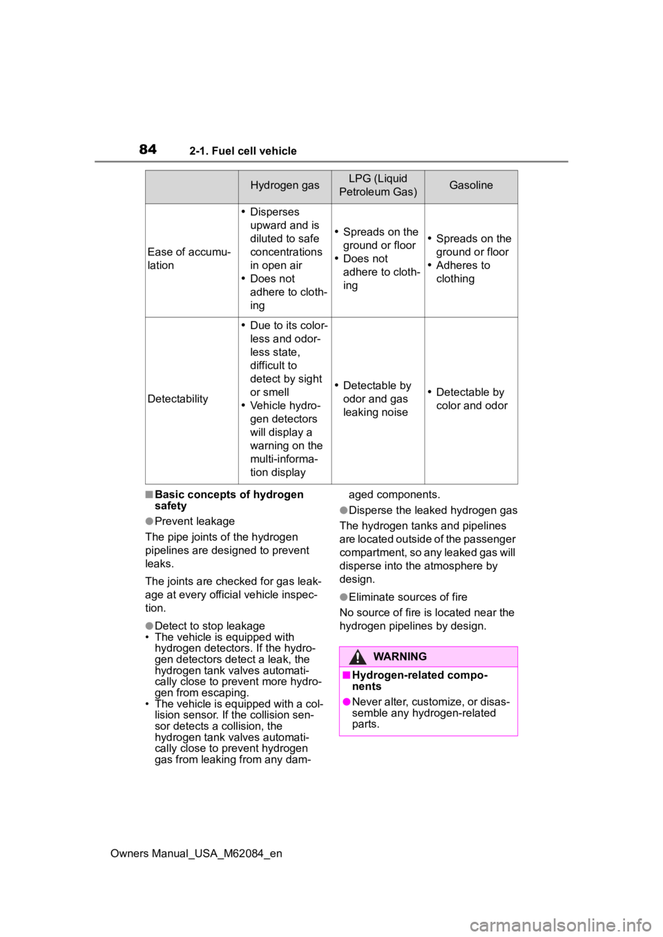
842-1. Fuel cell vehicle
Owners Manual_USA_M62084_en
■Basic concepts of hydrogen
safety
●Prevent leakage
The pipe joints o f the hydrogen
pipelines are designed to prevent
leaks.
The joints are checked for gas leak-
age at every official vehicle inspec-
tion.
●Detect to stop leakage
• The vehicle is equipped with
hydrogen detectors. If the hydro-
gen detectors detect a leak, the
hydrogen tank valves automati-
cally close to prevent more hydro-
gen from escaping.
• The vehicle is equipped with a col- lision sensor. If the collision sen-
sor detects a collision, the
hydrogen tank valves automati-
cally close to prevent hydrogen
gas from leaking from any dam- aged components.
●Disperse the leaked hydrogen gas
The hydrogen tanks and pipelines
are located outside of the passenger
compartment, so any leaked gas will
disperse into the atmosphere by
design.
●Eliminate sources of fire
No source of fire is located near the
hydrogen pipelines by design.
Ease of accumu-
lation
Disperses
upward and is
diluted to safe
concentrations
in open air
Does not
adhere to cloth-
ing
Spreads on the
ground or floor
Does not
adhere to cloth-
ingSpreads on the
ground or floor
Adheres to
clothing
Detectability
Due to its color-
less and odor-
less state,
difficult to
detect by sight
or smell
Vehicle hydro-
gen detectors
will display a
warning on the
multi-informa-
tion display
Detectable by
odor and gas
leaking noiseDetectable by
color and odor
Hydrogen gasLPG (Liquid
Petroleum Gas)Gasoline
WARNING
■Hydrogen-related compo-
nents
●Never alter, customize, or disas-
semble any hydrogen-related
parts.