navigation TOYOTA MIRAI 2022 Owners Manual
[x] Cancel search | Manufacturer: TOYOTA, Model Year: 2022, Model line: MIRAI, Model: TOYOTA MIRAI 2022Pages: 556, PDF Size: 17.34 MB
Page 18 of 556

18Pictorial index
Owners Manual_USA_M62084_en
Emergency flasher switch ....................................... .......... P.432
Audio system
*1
Air conditioning system*2................................................. P.332
Usage................................................................................... P.332
Air conditioning system ............................. ............... P.325, 332
Usage.......................................................... ................. P.325, 332
Rear window defogger ........................................... ...... P.327, 334
Trunk opener main switch ................................................. P.129
Shift lever.................................................... ........................ P.177
Changing the shift position.................................... ............... P.178
Precautions for towing .. ....................................... ................ P.435
Power switch ................................................... ................... P.172
Starting the fuel cell system/c hanging the modes ................P.172
Emergency stop of the fuel cell system ............................... P.432
When the fuel cell system will not start ....................... ......... P.466
Warning messages ............................................... ............... P.451
Tilt and telescopic st eering control switch
*2/tilt and telescopic
steering lock release lever
*2P.141
Adjustment ..................................................... ...................... P.141
Driving position memory .. .................................................... P.136
Hood lock release lever ........................................ ............. P.393
*1: Refer to “NAVIGATION AND MULTIMEDIA SYSTEM OWNER’S MAN-
UAL”.
*2: If equipped
Page 20 of 556
20Pictorial index
Owners Manual_USA_M62084_en
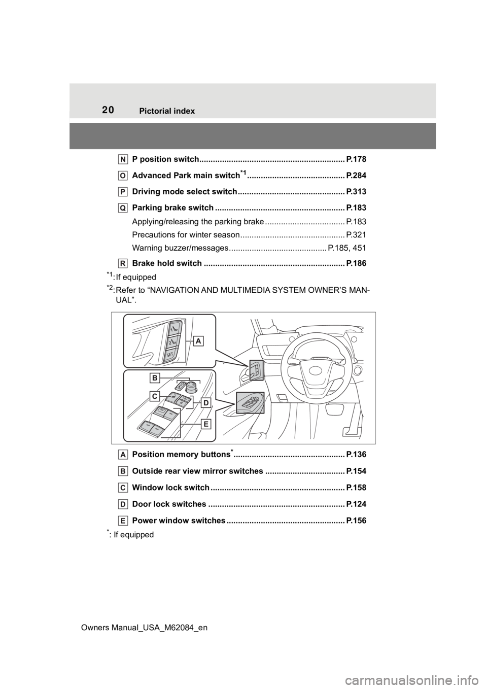
P position switch.............................................. .................. P.178
Advanced Park main switch
*1........................................... P.284
Driving mode select switch ..................................... .......... P.313
Parking brake switch ........................................... .............. P.183
Applying/releasing the parking brake ........................... ........ P.183
Precautions for winter seas on.............................................. P.321
Warning buzzer/messages.. ......................................... P.185, 451
Brake hold switch .............................................. ................ P.186
*1: If equipped
*2: Refer to “NAVIGATION AND MULTIMEDIA SYSTEM OWNER’S MAN-
UAL”.
Position memory buttons
*................................................. P.136
Outside rear view mirror swi tches ................................... P.154
Window lock switch ............................................. .............. P.158
Door lock switches ............................................................ P.124
Power window switches ....... ............................................. P.156
*: If equipped
Page 21 of 556
21Pictorial index
Owners Manual_USA_M62084_en
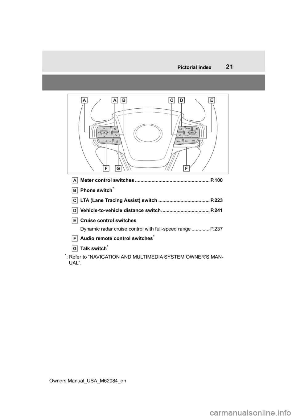
Meter control switches .. .................................................... P.100
Phone switch
*
LTA (Lane Tracing Assist) switch ............................... ...... P.223
Vehicle-to-vehicle distance switch ................................... P.241
Cruise control switches
Dynamic radar cruise control with full-speed range ............. P. 2 3 7
Audio remote control switches
*
Talk switch*
*
: Refer to “NAVIGATION AND MU LTIMEDIA SYSTEM OWNER’S MAN-
UAL”.
Page 77 of 556
772-1. Fuel cell vehicle
Owners Manual_USA_M62084_en
2
Fuel cell system
in order to warn people nearby
of the vehicle’s approach. The
sound will stop when the vehicle
speed exceeds approximately
23 mph (37 km/h).
■How to hear the warning
In the following ca ses, the acoustic
vehicle alerting system may be diffi-
cult for surrounding people to hear.
●In very noisy areas
●In the wind or the rain
Also, as the acoustic vehicle alerting
system is installed on the front of the
vehicle, it may be m ore difficult to
hear from the rear of the vehicle
compared to the front.
*: This function can only be used in
the mainland U.S.A. It cannot be
used in other states and territo-
ries, including Alaska and Hawaii.
This system operates based on
the driving situation to enhance
fuel economy. For details about
Predictive efficient drive, refer to
“NAVIGATION AND MULTIME-
DIA SYSTEM OWNER’S MAN-
UAL”.
■Predictive deceleration sup-
port
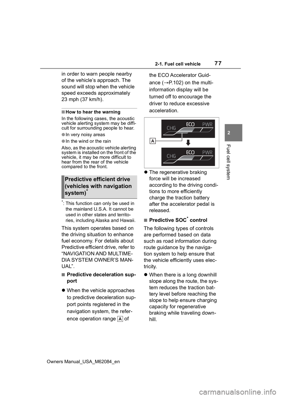
When the vehicle approaches
to predictive deceleration sup-
port points registered in the
navigation system, the refer-
ence operation range of the ECO Accelerator Guid-
ance (
P.102) on the multi-
information display will be
turned off to encourage the
driver to reduce excessive
acceleration.
The regenerative braking
force will be increased
according to the driving condi-
tions to more efficiently
charge the traction battery
after the accelerator pedal is
released.
■Predictive SOC* control
The following types of controls
are performed based on data
such as road information during
route guidance by the naviga-
tion system to help ensure that
the vehicle effici ently uses elec-
tricity.
When there is a long downhill
slope along the route, the sys-
tem reduces the traction bat-
tery level before reaching the
slope to help ensure charging
capacity for regenerative
braking while traveling down-
hill.
Predictive efficient drive
(vehicles with navigation
system)
*
Page 97 of 556
973-1. Instrument cluster
Owners Manual_USA_M62084_en
3
Vehicle status information and indicators
The units used on the meter and display may differ depending on the target
region.
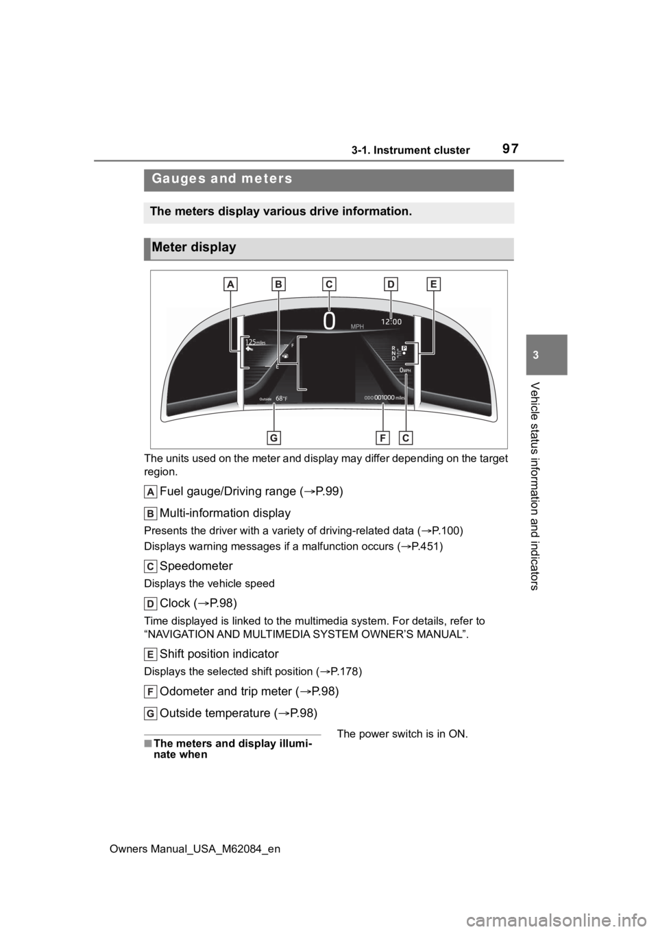
Fuel gauge/Driving range ( P. 9 9 )
Multi-information display
Presents the driver with a variety of driving-related data ( P.100)
Displays warning messages if a malfunction occurs (P.451)
Speedometer
Displays the vehicle speed
Clock ( P. 9 8 )
Time displayed is linked to the multimedia system. For details, refer to
“NAVIGATION AND MULTIMEDIA SYSTEM OWNER’S MANUAL”.
Shift position indicator
Displays the selected shift position ( P.178)
Odometer and trip meter ( P.98)
Outside temperature ( P. 9 8 )
■The meters and display illumi-
nate when The power switch is in ON.
Gauges and meters
The meters display various drive information.
Meter display
Page 101 of 556
1013-1. Instrument cluster
Owners Manual_USA_M62084_en
3
Vehicle status information and indicators
play customizable items
Return to the previous screen
Call sending/receiving and
history display
Linked with the hands-free system,
sending or receiv ing call is dis-
played. For details regarding the
hands-free system, refer to the
“NAVIGATION AND MULTIMEDIA
SYSTEM OWNER’S MANUAL”.
*: On screens where the screen can be scrolled and the display can
be switched, a scroll bar or a
round icon that shows the num-
ber of registered screens is dis-
played.
Information related to each icon
can be displayed by selecting
the icon with the meter control
switches.
Some of the information may be
displayed automatically depending
on the situation.
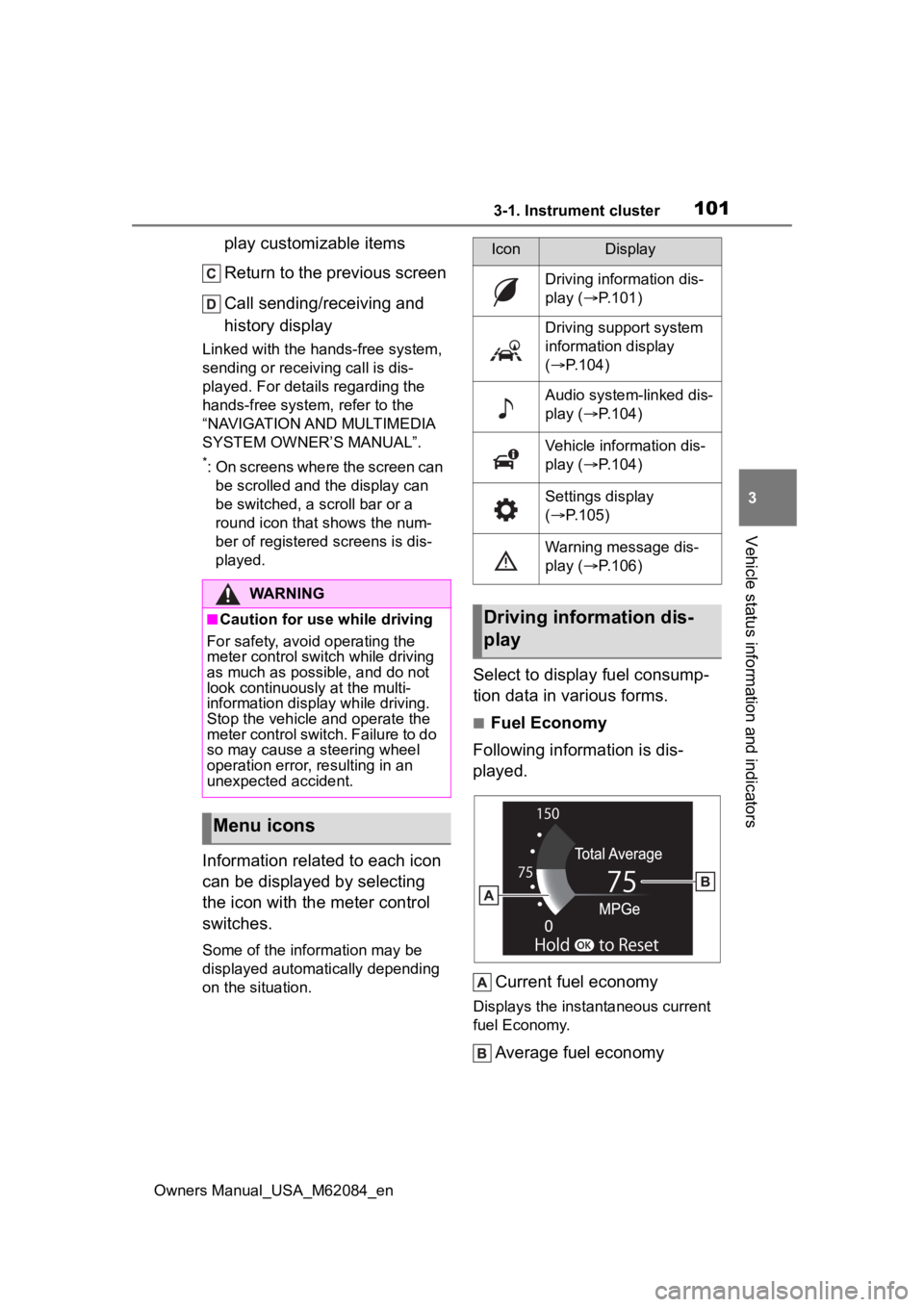
Select to display fuel consump-
tion data in various forms.
■Fuel Economy
Following information is dis-
played.
Current fuel economy
Displays the instantaneous current
fuel Economy.
Average fuel economy
WARNING
■Caution for use while driving
For safety, avoid operating the
meter control swit ch while driving
as much as possible, and do not
look continuously at the multi-
information display while driving.
Stop the vehicle and operate the
meter control switch. Failure to do
so may cause a steering wheel
operation error, resulting in an
unexpected accident.
Menu icons
IconDisplay
Driving information dis-
play ( P.101)
Driving support system
information display
( P.104)
Audio system-linked dis-
play ( P.104)
Vehicle information dis-
play ( P.104)
Settings display
( P.105)
Warning message dis-
play ( P.106)
Driving information dis-
play
Page 104 of 556
1043-1. Instrument cluster
Owners Manual_USA_M62084_en
■ECO Accelerator Guidance/Eco
Score will not operate when
The ECO Accelerator Guidance/Eco
Score will not opera te in the follow-
ing situations:
●The fuel cell system indicator is
not operating.
●The vehicle is being driven using
the dynamic radar cruise control
with full-speed range.
■Driving support system
information display
Select to display the operational
status of the following systems:
LTA (Lane Tracing Assist)
( P.223)
Dynamic radar cruise control
with full-speed range
( P.237)
■Navigation system-linked
display (if equipped)
Select to display the following
navigation system-linked infor-
mation.
Route guidance
Compass display (north-up
display/heading-up display)
Select to enable selection of an
audio source or track on the dis-
play.
■Drive information
2 items that are selected using
the “Drive Info Items” setting
(average speed, distance and
total time) can be displayed ver-
tically.
The displayed information
changes according to the “Drive
Info Type” setting (since the sys-
tem was started or between
resets). ( P.105)
Use the displayed information as a
reference only.
Following items will be displayed.
“Trip”
• “Average Speed”: Displays the
average vehicle speed since fuel
cell system start
*
• “Distance”: Displ ays the distance
driven since fuel cell system start
*
• “Total Time”: Displays the elapsed time since fuel cell system start
*
*
: These items are r eset each time
the fuel cell system stops.
“Total”
• “Average Speed”: Displays the
average vehicle speed since the
display was reset
*
• “Distance”: Displ ays the distance
driven since the display was
reset
*
• “Total Time”: Displays the elapsed
time since the display was reset
*
*
: To reset, display the desired item
Driving support system
information display
Audio system-linked dis-
play
Vehicle information dis-
play
Page 107 of 556
1073-1. Instrument cluster
Owners Manual_USA_M62084_en
3
Vehicle status information and indicators
*: If equipped
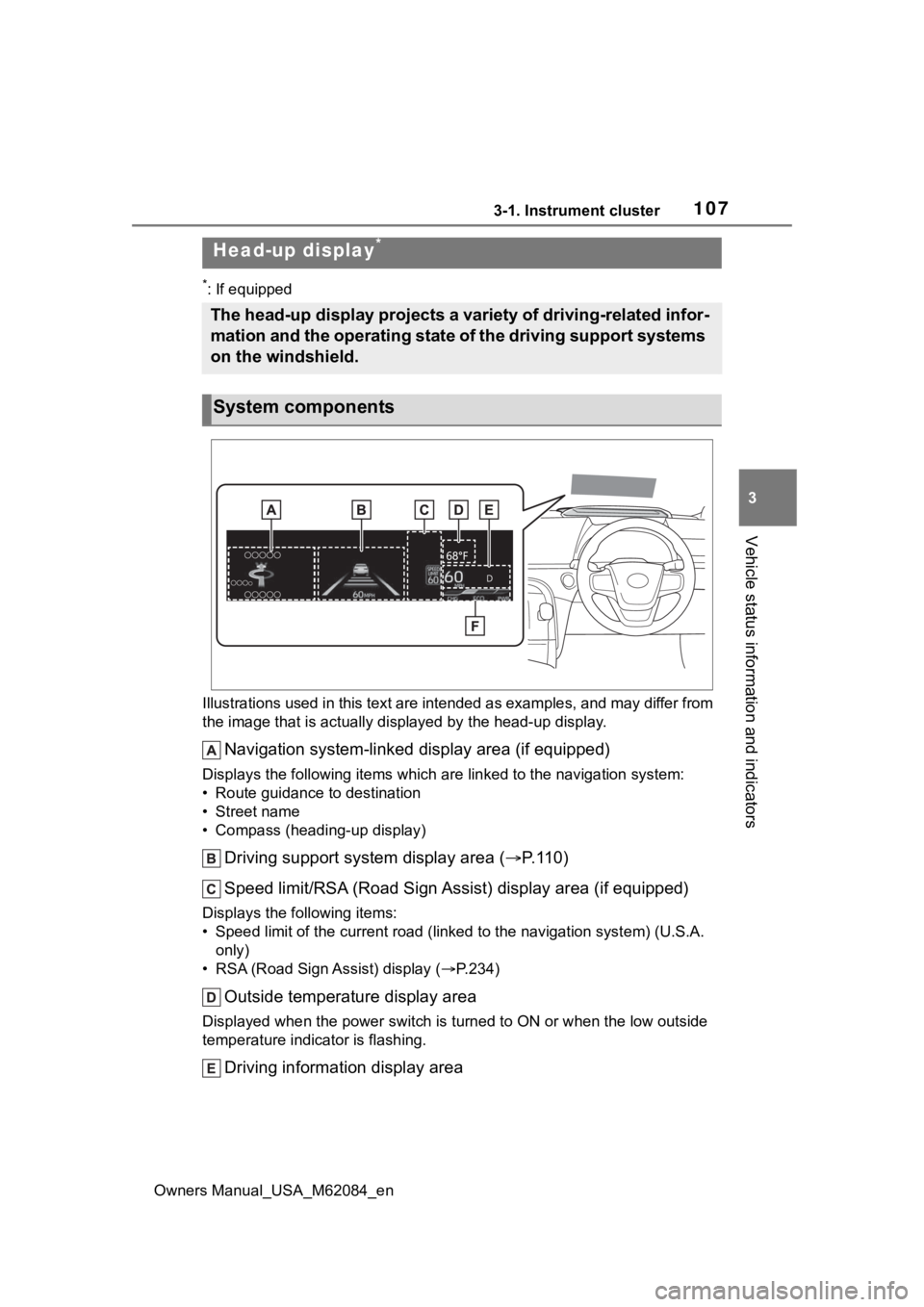
Illustrations used in this text are intended as examples, and m ay differ from
the image that is actually displayed by the he ad-up display.
Navigation system-linked display area (if equipped)
Displays the following items which are linked to the navigation system:
• Route guidance to destination
• Street name
• Compass (heading-up display)
Driving support system display area ( P.110)
Speed limit/RSA (Road Sign A ssist) display area (if equipped)
Displays the following items:
• Speed limit of the current road (linked to the navigation syst em) (U.S.A.
only)
• RSA (Road Sign Assist) display ( P.234)
Outside temperature display area
Displayed when the power switch i s turned to ON or when the low outside
temperature indicator is flashing.
Driving information display area
Head-up display*
The head-up display projects a variety of driving-related infor -
mation and the operating state of the driving support systems
on the windshield.
System components
Page 109 of 556
1093-1. Instrument cluster
Owners Manual_USA_M62084_en
3
Vehicle status information and indicators
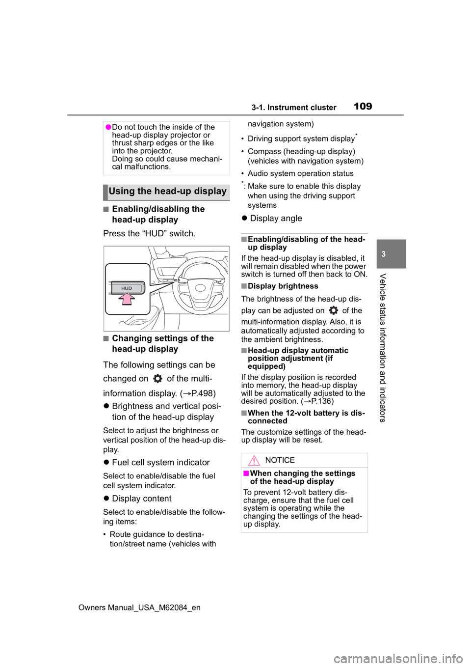
■Enabling/disabling the
head-up display
Press the “HUD” switch.
■Changing settings of the
head-up display
The following settings can be
changed on of the multi-
information display. ( P.498)
Brightness and vertical posi-
tion of the head-up display
Select to adjust t he brightness or
vertical position of the head-up dis-
play.
Fuel cell system indicator
Select to enable/d isable the fuel
cell system indicator.
Display content
Select to enable/d isable the follow-
ing items:
• Route guidance to destina- tion/street name (vehicles with navigation system)
• Driving support system display
*
• Compass (heading-up display) (vehicles with navigation system)
• Audio system operation status
*: Make sure to enable this display when using the driving support
systems
Display angle
■Enabling/disabling of the head-
up display
If the head-up display is disabled, it
will remain disabled when the power
switch is turned o ff then back to ON.
■Display brightness
The brightness of the head-up dis-
play can be adjusted on of the
multi-information di splay. Also, it is
automatically adjusted according to
the ambient brightness.
■Head-up display automatic
position adjustment (if
equipped)
If the display position is recorded
into memory, the head-up display
will be automatically adjusted to the
desired position. ( P.136)
■When the 12-volt battery is dis-
connected
The customize settings of the head-
up display will be reset.
●Do not touch the inside of the
head-up display projector or
thrust sharp edges or the like
into the projector.
Doing so could cause mechani-
cal malfunctions.
Using the head-up display
NOTICE
■When changing the settings
of the head-up display
To prevent 12-volt battery dis-
charge, ensure that the fuel cell
system is operating while the
changing the settings of the head-
up display.
Page 234 of 556
2345-5. Using the driving support systems
Owners Manual_USA_M62084_en
*: If equipped
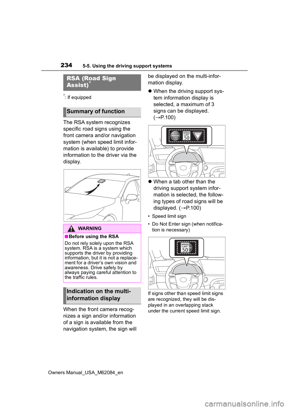
The RSA system recognizes
specific road signs using the
front camera and/or navigation
system (when speed limit infor-
mation is available) to provide
information to the driver via the
display.
When the front camera recog-
nizes a sign and/or information
of a sign is available from the
navigation system, the sign will be displayed on the multi-infor-
mation display.
When the driving support sys-
tem information display is
selected, a maximum of 3
signs can be displayed.
( P.100)
When a tab other than the
driving support system infor-
mation is selected, the follow-
ing types of road signs will be
displayed. ( P.100)
• Speed limit sign
• Do Not Enter sign (when notifica-
tion is necessary)
If signs other than speed limit signs
are recognized, they will be dis-
played in an overlapping stack
under the current speed limit sign.
RSA (Road Sign
Assist)*
Summary of function
WARNING
■Before using the RSA
Do not rely solely upon the RSA
system. RSA is a system which
supports the driver by providing
information, but it is not a replace-
ment for a driver’s own vision and
awareness. Drive safely by
always paying careful attention to
the traffic rules.
Indication on the multi-
information display