TOYOTA PRIUS 2001 Service Repair Manual
PRIUS 2001
TOYOTA
TOYOTA
https://www.carmanualsonline.info/img/14/57461/w960_57461-0.png
TOYOTA PRIUS 2001 Service Repair Manual
Trending: check transmission fluid, fog light bulb, roof, compression ratio, octane, power steering fluid, engine oil
Page 1051 of 1943
F12824
ONIG
PGND
F12825
LOCK
PGND
± DIAGNOSTICSELECTRIC MOTOR POWER STEERING
DI±483
2001 PRIUS (RM778U)
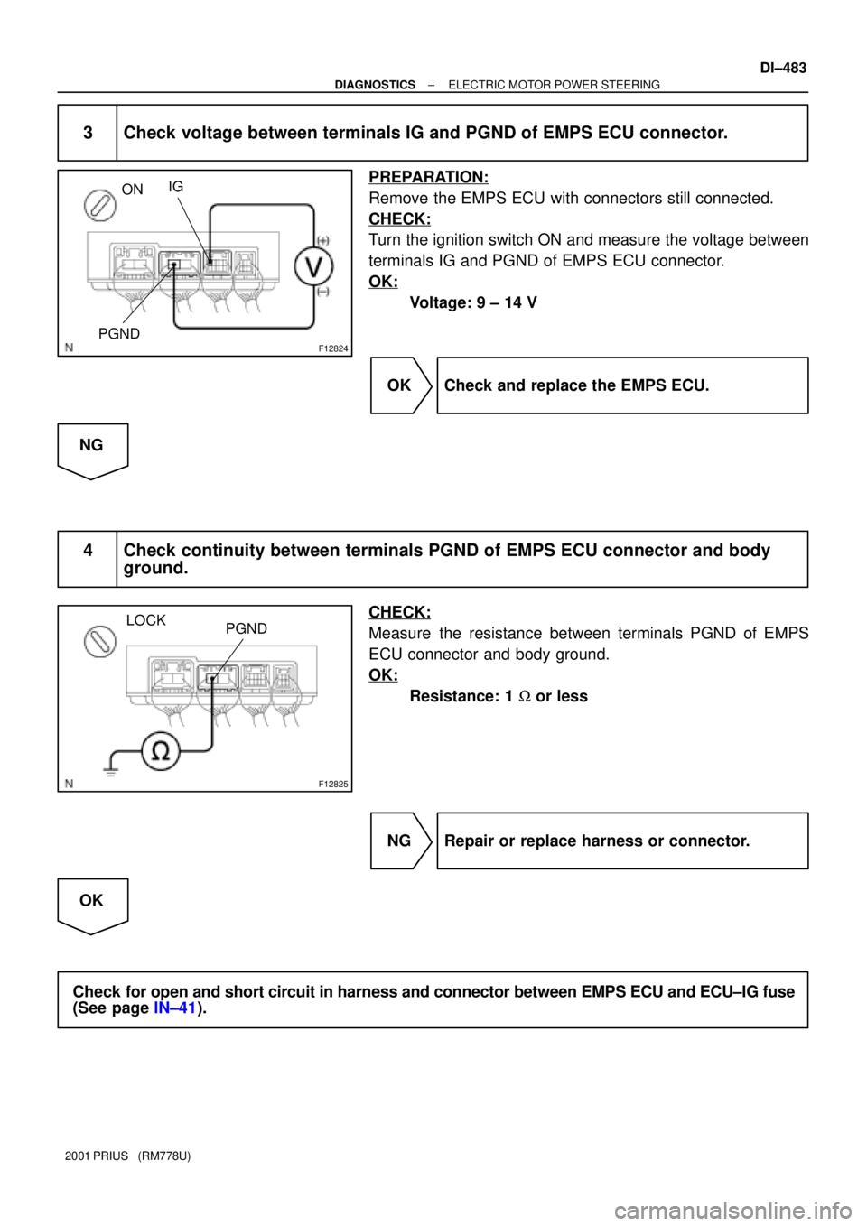
3 Check voltage between terminals IG and PGND of EMPS ECU connector.
PREPARATION:
Remove the EMPS ECU with connectors still connected.
CHECK:
Turn the ignition switch ON and measure the voltage between
terminals IG and PGND of EMPS ECU connector.
OK:
Voltage: 9 ± 14 V
OK Check and replace the EMPS ECU.
NG
4 Check continuity between terminals PGND of EMPS ECU connector and body
ground.
CHECK:
Measure the resistance between terminals PGND of EMPS
ECU connector and body ground.
OK:
Resistance: 1 W or less
NG Repair or replace harness or connector.
OK
Check for open and short circuit in harness and connector between EMPS ECU and ECU±IG fuse
(See page IN±41).
Page 1052 of 1943
F12839
PIG
RLY E5
E61
2 B
GR IM1
IA21
7 B
GR 3
3 3
31 35
2 EMPS Relay
R±G B±R
Instrument Panel J/B
ECU±B
6
2G 2H1
W
F111
F101
WFL Block No. 1
DC/DC
F131
Engine Room R/B No. 3
3
321EMPS
FL Block No. 2 F18
MAIN
1
E52
PGND W±B
A J17
J/C
IG BatteryEngine Room R/B No. 3 DI±484
± DIAGNOSTICSELECTRIC MOTOR POWER STEERING
2001 PRIUS (RM778U)
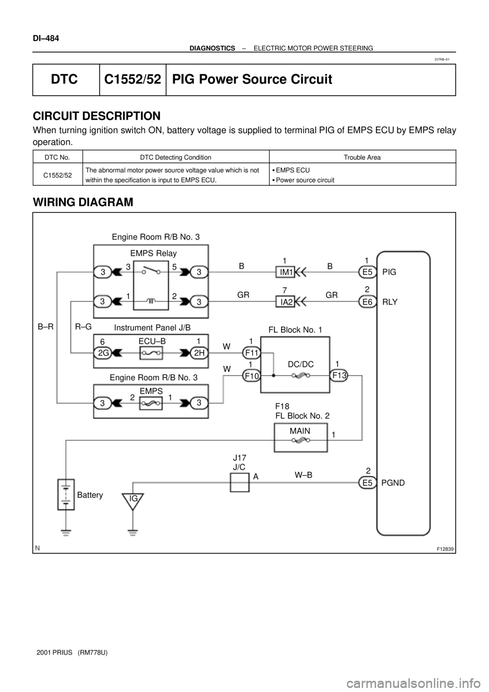
DTC C1552/52 PIG Power Source Circuit
CIRCUIT DESCRIPTION
When turning ignition switch ON, battery voltage is supplied to terminal PIG of EMPS ECU by EMPS relay
operation.
DTC No.DTC Detecting ConditionTrouble Area
C1552/52The abnormal motor power source voltage value which is not
within the specification is input to EMPS ECU.�EMPS ECU
�Power source circuit
WIRING DIAGRAM
DI7R8±01
Page 1053 of 1943
F16035
ON
PIG PGND
F12825
LOCK
PGND
± DIAGNOSTICSELECTRIC MOTOR POWER STEERING
DI±485
2001 PRIUS (RM778U)
5/18/01
INSPECTION PROCEDURE
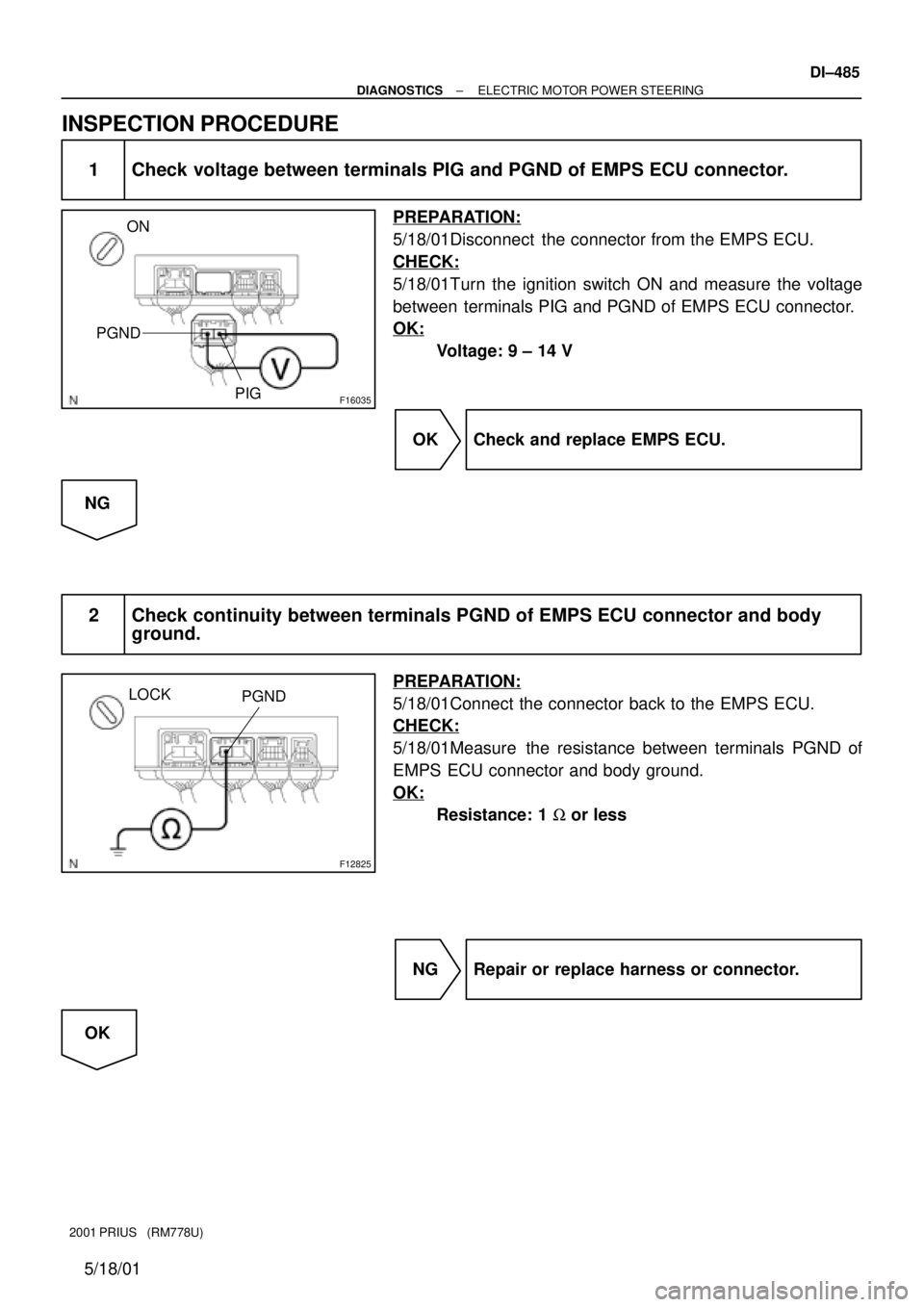
1 Check voltage between terminals PIG and PGND of EMPS ECU connector.
PREPARATION:
5/18/01Disconnect the connector from the EMPS ECU.
CHECK:
5/18/01Turn the ignition switch ON and measure the voltage
between terminals PIG and PGND of EMPS ECU connector.
OK:
Voltage: 9 ± 14 V
OK Check and replace EMPS ECU.
NG
2 Check continuity between terminals PGND of EMPS ECU connector and body
ground.
PREPARATION:
5/18/01Connect the connector back to the EMPS ECU.
CHECK:
5/18/01Measure the resistance between terminals PGND of
EMPS ECU connector and body ground.
OK:
Resistance: 1 W or less
NG Repair or replace harness or connector.
OK
Page 1054 of 1943
F12862
Engine Room
R/B No. 3
EMPS
Fuse
DI±486
± DIAGNOSTICSELECTRIC MOTOR POWER STEERING
2001 PRIUS (RM778U)
3 Check EMPS fuse.
PREPARATION:
5/18/01Remove the EMPS fuse from engine room R/B No. 3.
CHECK:
5/18/01Check continuity of EMPS fuse.
OK:
Continuity
NG Check for short circuit in harness and all com-
ponents connected to EMPS fuse (See attached
wiring diagram).
OK
Check for open and short circuit in harness and connector between EMPS ECU and battery
(See page IN±41).
Page 1055 of 1943
F12839
PIG
RLY E5
E61
2 B
GR IM1
IM21
7 B
GR 3
3 3
31 35
2 EMPS Relay
R±G B±R
Instrument Panel J/B
ECU±B
6
2G
2H1
W
F111
F101
WFL Block No. 1
DC/DC
F131
Engine Room R/B No. 3
3
321EMPS
FL Block No. 2 F18
MAIN
1
E52
PGND W±B
A J17
J/C
IG BatteryEngine Room R/B No. 3 DI±488
± DIAGNOSTICSELECTRIC MOTOR POWER STEERING
2001 PRIUS (RM778U)
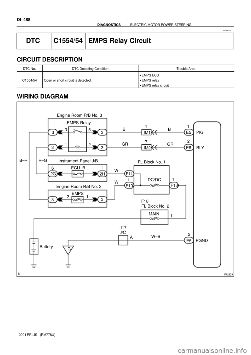
DTC C1554/54 EMPS Relay Circuit
CIRCUIT DESCRIPTION
DTC No.DTC Detecting ConditionTrouble Area
C1554/54Open or short circuit is detected.
�EMPS ECU
�EMPS relay
�EMPS relay circuit
WIRING DIAGRAM
DI7RA±01
Page 1056 of 1943
F12828
ON
RLY
PGND
F11788
5
13
2
Open
Continuity
5
2 1
3
5
2 1
3 Continuity
± DIAGNOSTICSELECTRIC MOTOR POWER STEERING
DI±489
2001 PRIUS (RM778U)
INSPECTION PROCEDURE
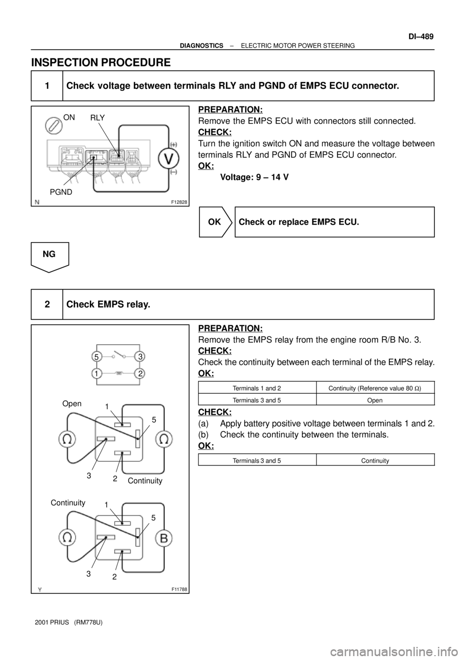
1 Check voltage between terminals RLY and PGND of EMPS ECU connector.
PREPARATION:
Remove the EMPS ECU with connectors still connected.
CHECK:
Turn the ignition switch ON and measure the voltage between
terminals RLY and PGND of EMPS ECU connector.
OK:
Voltage: 9 ± 14 V
OK Check or replace EMPS ECU.
NG
2 Check EMPS relay.
PREPARATION:
Remove the EMPS relay from the engine room R/B No. 3.
CHECK:
Check the continuity between each terminal of the EMPS relay.
OK:
Terminals 1 and 2Continuity (Reference value 80 W)
Terminals 3 and 5Open
CHECK:
(a) Apply battery positive voltage between terminals 1 and 2.
(b) Check the continuity between the terminals.
OK:
Terminals 3 and 5Continuity
Page 1057 of 1943
F12863
Instrument
Panel J/BECU±B
Fuse
DI±490
± DIAGNOSTICSELECTRIC MOTOR POWER STEERING
2001 PRIUS (RM778U)
NG Replace EMPS relay.
OK
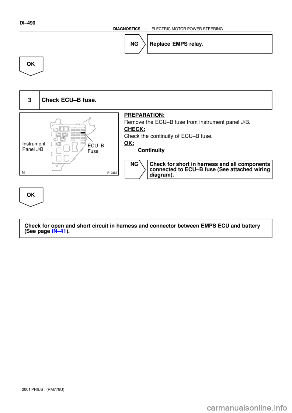
3 Check ECU±B fuse.
PREPARATION:
Remove the ECU±B fuse from instrument panel J/B.
CHECK:
Check the continuity of ECU±B fuse.
OK:
Continuity
NG Check for short in harness and all components
connected to ECU±B fuse (See attached wiring
diagram).
OK
Check for open and short circuit in harness and connector between EMPS ECU and battery
(See page IN±41).
Page 1058 of 1943
F12840
EMPS ECU
WL
E67
Y 3
IP1 L 11 Multiinformation Display
22
L
Instrument Panel J/B
IG1 Relay
3
51
2H GAUGE
2A5
W
FL Block No. 1
1
F11 F131
B±G
1 MAIN FL Block No. 2 F18
BatteryDC/DC
± DIAGNOSTICSELECTRIC MOTOR POWER STEERING
DI±491
2001 PRIUS (RM778U)
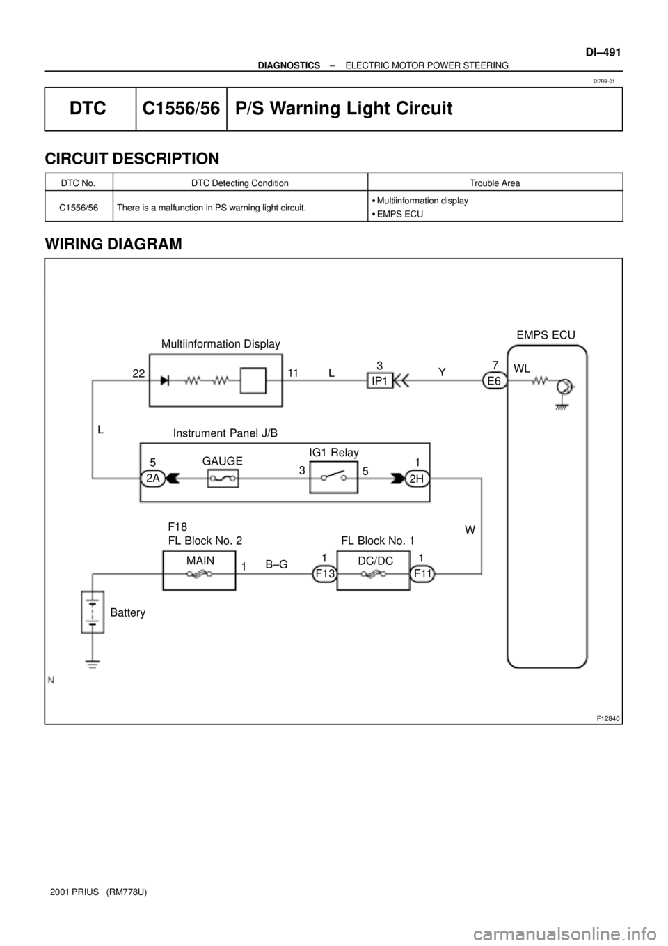
DTC C1556/56 P/S Warning Light Circuit
CIRCUIT DESCRIPTION
DTC No.DTC Detecting ConditionTrouble Area
C1556/56There is a malfunction in PS warning light circuit.�Multiinformation display
�EMPS ECU
WIRING DIAGRAM
DI7RB±01
Page 1059 of 1943
F12829
ON
WL
DI±492
± DIAGNOSTICSELECTRIC MOTOR POWER STEERING
2001 PRIUS (RM778U)
INSPECTION PROCEDURE
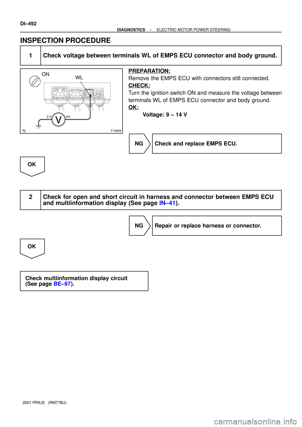
1 Check voltage between terminals WL of EMPS ECU connector and body ground.
PREPARATION:
Remove the EMPS ECU with connectors still connected.
CHECK:
Turn the ignition switch ON and measure the voltage between
terminals WL of EMPS ECU connector and body ground.
OK:
Voltage: 9 ± 14 V
NG Check and replace EMPS ECU.
OK
2 Check for open and short circuit in harness and connector between EMPS ECU
and multiinformation display (See page IN±41).
NG Repair or replace harness or connector.
OK
Check multiinformation display circuit
(See page BE±97).
Page 1060 of 1943
DI±494
± DIAGNOSTICSELECTRIC MOTOR POWER STEERING
2001 PRIUS (RM778U)
DTCAlways ONMalfunction in EMPS ECU
CIRCUIT DESCRIPTION
DTC No.DTC Detecting ConditionTrouble Area
Always ONThere is a malfunction in the EMPS ECU internal circuit.
�Power source circuit
�EMPS ECU
�PS warning light circuit
INSPECTION PROCEDURE
1 Is DTC output?
Check DTC on page DI±460.
YES Repair circuit indicated by output code.
NO
2 Is normal code displayed?
YES Check and replace EMPS ECU.
NO
3 Does PS warning light goes off?
YES Check for open or short circuit in harness and
connector between ECU±IG fuse and EMPS
ECU (See page IN±41).
NO
DI7RD±01
Trending: relay, lights, tow, belt, ignition system, trailer, battery replacement
