TOYOTA PRIUS 2001 Service Repair Manual
PRIUS 2001
TOYOTA
TOYOTA
https://www.carmanualsonline.info/img/14/57461/w960_57461-0.png
TOYOTA PRIUS 2001 Service Repair Manual
Trending: airbag off, ignition system, trailer, coolant temperature, O2 sensor, dimensions, engine overheat
Page 891 of 1943
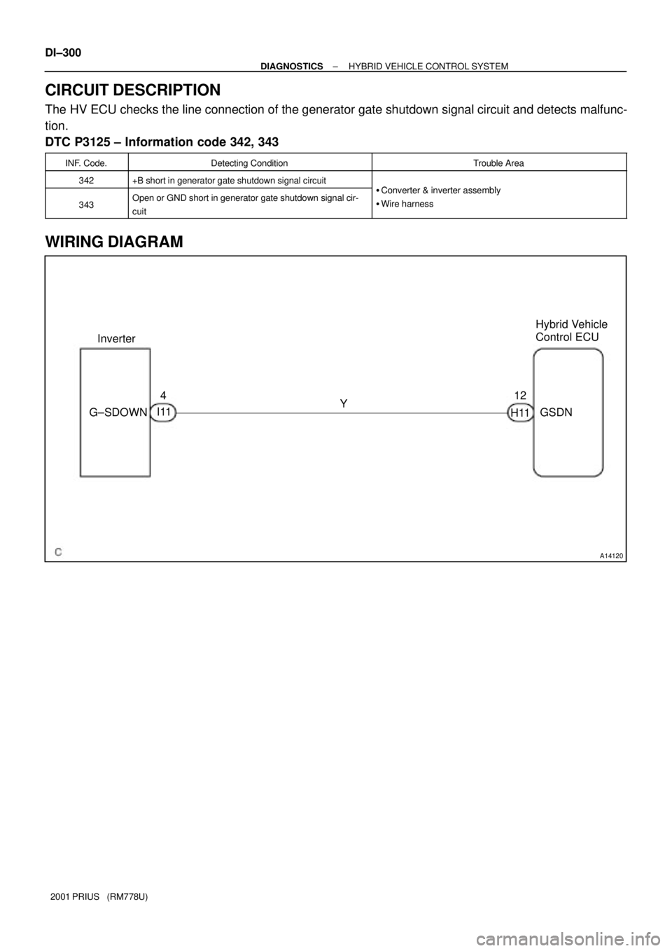
A14120
InverterHybrid Vehicle
Control ECU
G±SDOWNY 4
I1112
GSDN
H11 DI±300
± DIAGNOSTICSHYBRID VEHICLE CONTROL SYSTEM
2001 PRIUS (RM778U)
CIRCUIT DESCRIPTION
The HV ECU checks the line connection of the generator gate shutdown signal circuit and detects malfunc-
tion.
DTC P3125 ± Information code 342, 343
INF. Code.Detecting ConditionTrouble Area
342+B short in generator gate shutdown signal circuitCt&it bl
343Open or GND short in generator gate shutdown signal cir-
cuit�Converter & inverter assembly
�Wire harness
WIRING DIAGRAM
Page 892 of 1943
± DIAGNOSTICSHYBRID VEHICLE CONTROL SYSTEM
DI±301
2001 PRIUS (RM778U)
INSPECTION PROCEDURE
1 Check for open, short and +B short in wire harness between HV ECU GSDN ter-
minal and converter & inverter assembly G±SDOWN terminals (See page
IN±41).
HINT:
Confirm that there is no open circuit in the wire harness. The generator gate shutdown signal circuit has +B
short if the battery voltage is always applied to the HV ECU GSDN terminal with the ignition ON.
NG Repair or replace wire harness.
OK
Replace converter & inverter assembly.
Page 893 of 1943
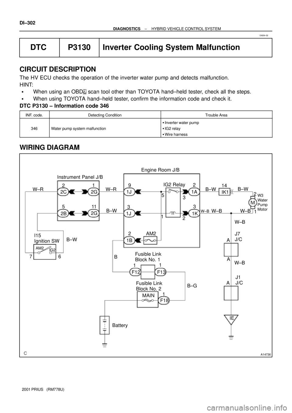
A14736
BatteryMAINB±G 1
1
F18 1 1
5
1
F132 3 2
2Engine Room J/B
W±B IK1 2
14
5
AM2 B±WB±W
B±W I15
Ignition SW W±R
6 711
IG2 AM2
Instrument Panel J/B
2C
1K 1A 2G9
1J
1B
B
F12IG2 Relay
Fusible Link
Block No. 1
Fusible Link
Block No. 2 1J
2G
2BW±R
13 3
IE AA AB±W
2
W±B W±B
W±BW3
Water
Pump
Motor
J1
J/C J7
J/C W±B DI±302
± DIAGNOSTICSHYBRID VEHICLE CONTROL SYSTEM
2001 PRIUS (RM778U)
DTC P3130 Inverter Cooling System Malfunction
CIRCUIT DESCRIPTION
The HV ECU checks the operation of the inverter water pump and detects malfunction.
HINT:
�When using an OBD scan tool other than TOYOTA hand±held tester, check all the steps.
�When using TOYOTA hand±held tester, confirm the information code and check it.
DTC P3130 ± Information code 346
INF. code.Detecting ConditionTrouble Area
346Water pump system malfunction
�Inverter water pump
�IG2 relay
�Wire harness
WIRING DIAGRAM
DI839±02
Page 894 of 1943
± DIAGNOSTICSHYBRID VEHICLE CONTROL SYSTEM
DI±303
2001 PRIUS (RM778U)
INSPECTION PROCEDURE
1Check wire harness (See page IN±41).
HINT:
After removing the IG2 relay, check the electrical condition of each terminal.
�No. 1 terminal: With the IG switch ON, 10 ± 14 V
�No. 2 terminal : Continuity between the IG2 relay No. 2 terminal and body ground (less than 1 W )
�No. 3 terminal: Continuity between the IG2 relay No. 3 terminal and water pump No. 2 terminal (less
than 1 W )
�No. 5 terminal: Always 10 ± 14 V
Continuity between the water pump No. 1 terminal and body ground (less than 1 W )
NG Repair or replace wire harness.
OK
Page 895 of 1943
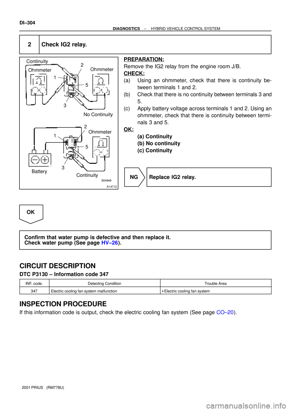
S04947S04946
A14712
Continuity
OhmmeterOhmmeter
No Continuity 2
1
5
3
Ohmmeter
Continuity2
1
5
3
Battery
DI±304
± DIAGNOSTICSHYBRID VEHICLE CONTROL SYSTEM
2001 PRIUS (RM778U)
2 Check IG2 relay.
PREPARATION:
Remove the IG2 relay from the engine room J/B.
CHECK:
(a) Using an ohmmeter, check that there is continuity be-
tween terminals 1 and 2.
(b) Check that there is no continuity between terminals 3 and
5.
(c) Apply battery voltage across terminals 1 and 2. Using an
ohmmeter, check that there is continuity between termi-
nals 3 and 5.
OK:
(a) Continuity
(b) No continuity
(c) Continuity
NG Replace IG2 relay.
OK
Confirm that water pump is defective and then replace it.
Check water pump (See page HV±26).
CIRCUIT DESCRIPTION
DTC P3130 ± Information code 347
INF. code.Detecting ConditionTrouble Area
347Electric cooling fan system malfunction�Electric cooling fan system
INSPECTION PROCEDURE
If this information code is output, check the electric cooling fan system (See page CO±20).
Page 896 of 1943
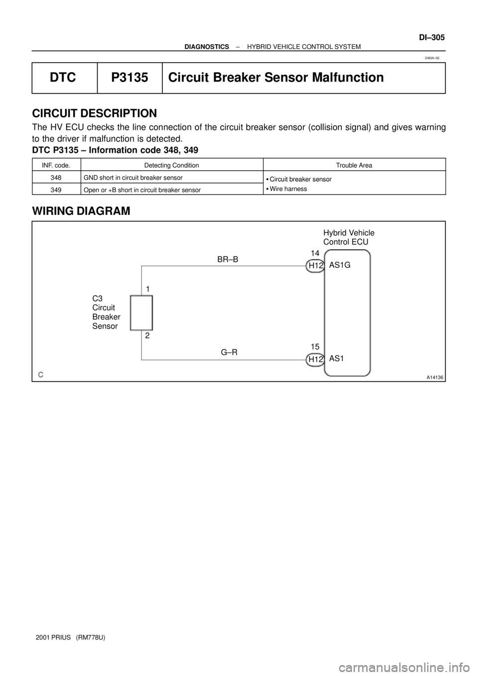
A14136
C3
Circuit
Breaker
Sensor1
2
H12AS1G Hybrid Vehicle
Control ECU
BR±B
G±RH1214
15
AS1
± DIAGNOSTICSHYBRID VEHICLE CONTROL SYSTEM
DI±305
2001 PRIUS (RM778U)
DTC P3135 Circuit Breaker Sensor Malfunction
CIRCUIT DESCRIPTION
The HV ECU checks the line connection of the circuit breaker sensor (collision signal) and gives warning
to the driver if malfunction is detected.
DTC P3135 ± Information code 348, 349
INF. code.Detecting ConditionTrouble Area
348GND short in circuit breaker sensor�Circuit breaker sensor
349Open or +B short in circuit breaker sensor
�Circuit breaker sensor
�Wire harness
WIRING DIAGRAM
DI83A±02
Page 897 of 1943
DI±306
± DIAGNOSTICSHYBRID VEHICLE CONTROL SYSTEM
2001 PRIUS (RM778U)
INSPECTION PROCEDURE
1 Check for open, short and +B short in wire harness between circuit breaker sen-
sor No. 1 and No. 2 terminals and HV ECU AS1G and AS1 terminals
(See page IN±41).
HINT:
Confirm that there is no open circuit in the wire harness. The circuit breaker sensor circuit has +B short if
the voltage of the HV ECU AS1 terminal is more than 5V with the ignition ON.
NG Repair or replace wire harness.
OK
Check for open in resistance between circuit breaker sensor terminals and then replace circuit
breaker sensor (Circuit breaker sensor resistance: 820 ± 82 W).
Page 898 of 1943
± DIAGNOSTICSHYBRID VEHICLE CONTROL SYSTEM
DI±307
2001 PRIUS (RM778U)
DTC P3140 Interlock Malfunction
CIRCUIT DESCRIPTION
If the HV ECU detects the operation of the safety devices (removal of the service plug, inverter terminal cover
and sensor cover) while the vehicle is not running (with the vehicle is stopped), it will shut down the system
main relay. It the safety devices are correctly installed, it will resume the normal operation after the power
source is supplied again. If it does not, there is a possibility of an open circuit, so perform the same inspection
as the information code 351.
HINT:
�When using an OBD scan tool other than TOYOTA hand±held tester, check all the steps.
�When using TOYOTA hand±held tester, confirm the information code and check it.
DTC P3140 ± Information code 350
INF. code.Detecting ConditionTrouble Area
350Safety devices operating with vehicle is stopped (ILK signal
ON)±
DI83B±02
Page 899 of 1943
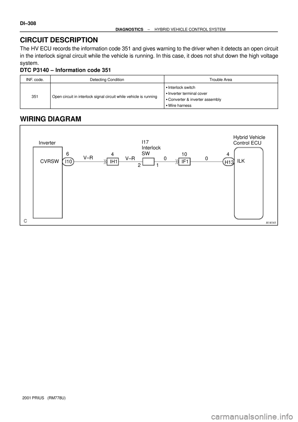
A14141
Inverter
1 2 IH1 CVRSWHybrid Vehicle
Control ECU
V±R
H13 10
ILK 6
4
004
IF1 V±R
I10I17
Interlock
SW DI±308
± DIAGNOSTICSHYBRID VEHICLE CONTROL SYSTEM
2001 PRIUS (RM778U)
CIRCUIT DESCRIPTION
The HV ECU records the information code 351 and gives warning to the driver when it detects an open circuit
in the interlock signal circuit while the vehicle is running. In this case, it does not shut down the high voltage
system.
DTC P3140 ± Information code 351
INF. code.Detecting ConditionTrouble Area
351Open circuit in interlock signal circuit while vehicle is running
�Interlock switch
�Inverter terminal cover
�Converter & inverter assembly
�Wire harness
WIRING DIAGRAM
Page 900 of 1943
± DIAGNOSTICSHYBRID VEHICLE CONTROL SYSTEM
DI±309
2001 PRIUS (RM778U)
INSPECTION PROCEDURE
1 Check installation condition of inverter terminal cover and sensor cover.
NG Install them correctly.
OK
2 Check continuity of wire harness between interlock switch No. 1 terminal and HV
ECU ILK terminal and interlock switch No. 2 terminal and inverter CVRSW termi-
nal (See page IN±41).
OK:
Continuity: Less than 1 W
NG Repair or replace wire harness.
OK
3 Check continuity between inverter CVRSW terminal and body ground
(See page IN±41).
OK:
Continuity: Less than 1 W
NG Replace converter & inverter assembly.
OK
Confirm that interlock switch is defective and replace it.
Check interlock switch (See page HV±38)
Trending: relay, oil type, engine oil, wheelbase, Door key lock, key battery, CD player
