Power outlet TOYOTA PRIUS PRIME 2023 Owners Manual
[x] Cancel search | Manufacturer: TOYOTA, Model Year: 2023, Model line: PRIUS PRIME, Model: TOYOTA PRIUS PRIME 2023Pages: 680, PDF Size: 14.97 MB
Page 4 of 680
4TABLE OF CONTENTS
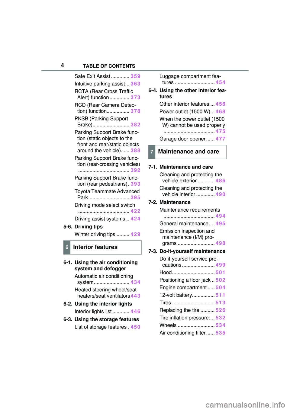
Safe Exit Assist .............359
Intuitive parking assist... 363
RCTA (Rear Cross Traffic Alert) function .............. 373
RCD (Rear Camera Detec- tion) function................ 378
PKSB (Parking Support Brake).......................... 382
Parking Support Brake func- tion (static objects to the
front and rear/static objects
around the vehicle)...... 388
Parking Support Brake func- tion (rear-crossing vehicles).................................... 392
Parking Support Brake func- tion (rear pedestrians) . 393
Toyota Teammate Advanced Park ............................. 395
Driving mode select switch .................................... 422
Driving assist systems .. 424
5-6. Driving tips Winter driving tips ......... 429
6-1. Using the air conditioning system and defogger
Automatic air conditioning system ......................... 434
Heated steering wheel/seat heaters/seat ventilators 443
6-2. Using the interior lights Interior lights list ............ 446
6-3. Using the storage features List of storage features . 450Luggage compartment fea-
tures ............................ 454
6-4. Using the other interior fea- tures
Other interior features ... 456
Power outlet (1500 W)... 468
When the power outlet (1500 W) cannot be used properly
.................................... 475
Garage door opener ...... 477
7-1. Maintenance and care Cleaning and protecting the vehicle exterior ............ 486
Cleaning and protecting the vehicle interior ............. 490
7-2. Maintenance Maintenance requirements.................................... 494
General maintenance .... 495
Emission inspection and maintenance (I/M) pro-
grams .......................... 498
7-3. Do-it-yourself maintenance Do-it-yourself service pre-cautions ....................... 499
Hood .............................. 501
Positioning a floor jack .. 502
Engine compartment ..... 504
12-volt battery................ 511
Tires .............................. 513
Replacing the tire .......... 526
Tire inflation pressure .... 532
Wheels .......................... 534
Air conditioning filter ...... 53
5
6Interior features
7Maintenance and care
Page 21 of 680
21Pictorial index
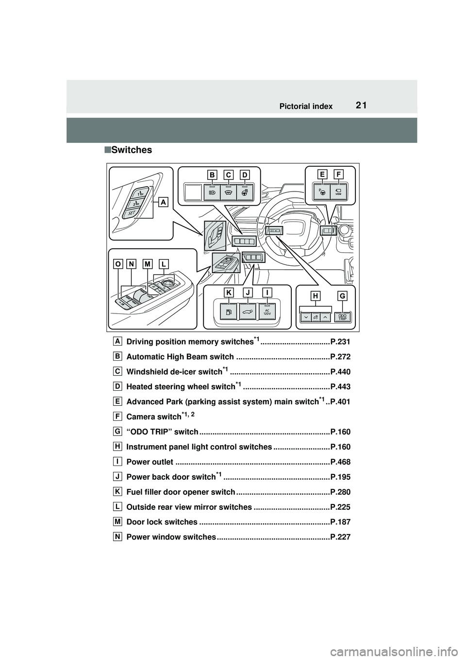
■Switches
Driving position memory switches*1................................P.231
Automatic High Beam switch ...........................................P.272
Windshield de-icer switch
*1..............................................P.440
Heated steering wheel switch
*1........................................P.443
Advanced Park (parking assist system) main switch
*1..P.401
Camera switch
*1, 2
“ODO TRIP” switch ............................................................P.160
Instrument panel light control switches ..........................P.160
Power outlet .......................................................................P.468
Power back door switch
*1.................................................P.195
Fuel filler door opener switch ...........................................P.280
Outside rear view mirror switches ...................................P.225
Door lock switches ............................................................P.187
Power window switches ................................. ...................P.227
A
B
C
D
E
F
G
H
I
J
K
L
M
N
Page 23 of 680
23Pictorial index
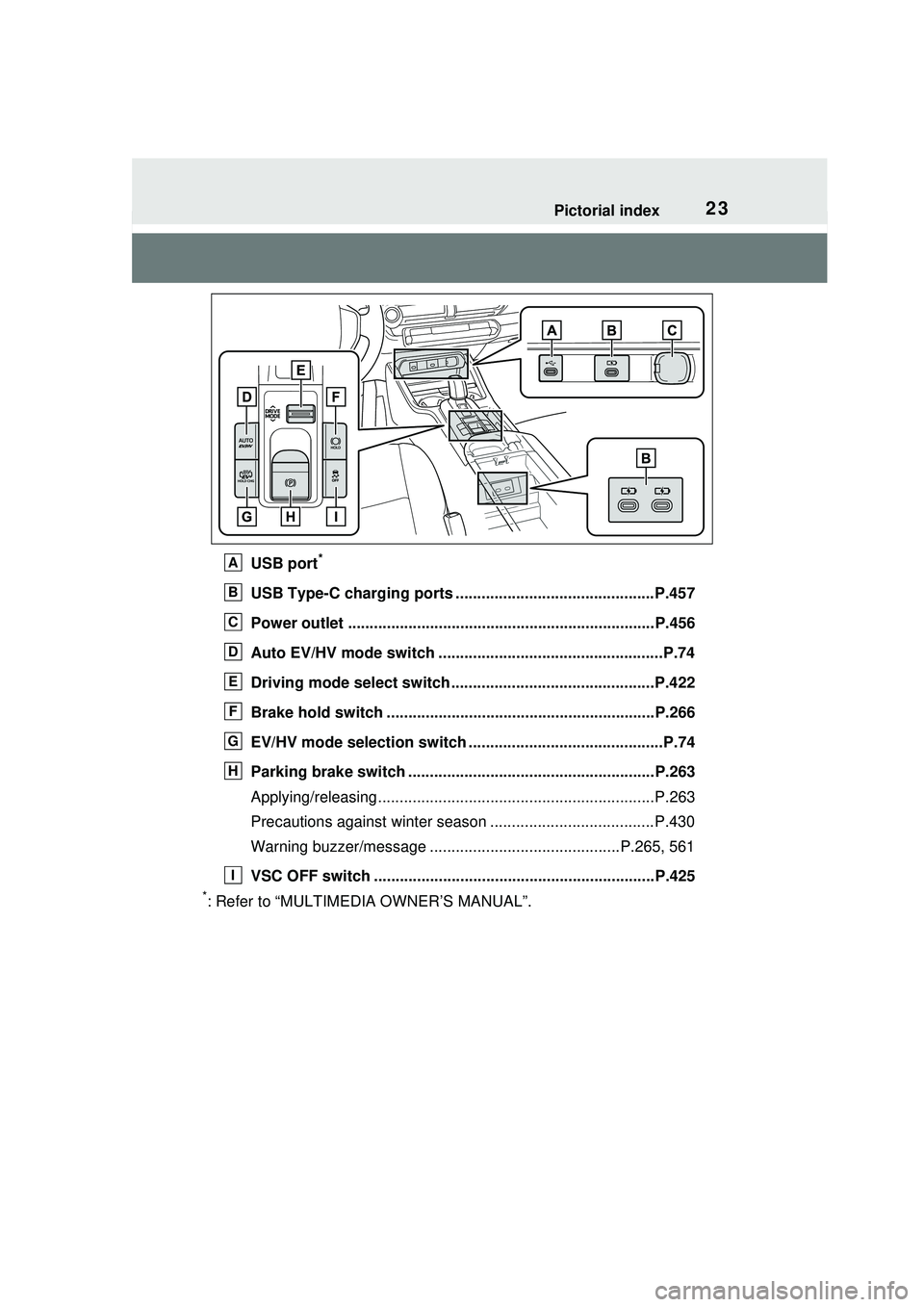
USB port*
USB Type-C charging ports ..............................................P.457
Power outlet .......................................................................P.456
Auto EV/HV mode switch ....................................................P.74
Driving mode select switch ...............................................P.422
Brake hold switch ..............................................................P.266
EV/HV mode selection switch .............................................P.74
Parking brake switch .........................................................P.263
Applying/releasing................................................................P.263
Precautions against winter season ......................................P.430
Warning buzzer/message ............................................P.265, 561
VSC OFF switch .................................................................P.425
*: Refer to “MULTIMEDIA OWNER’S MANUAL”.
A
B
C
D
E
F
G
H
I
Page 99 of 680
992-2. Charging
2
Plug-in hybrid system
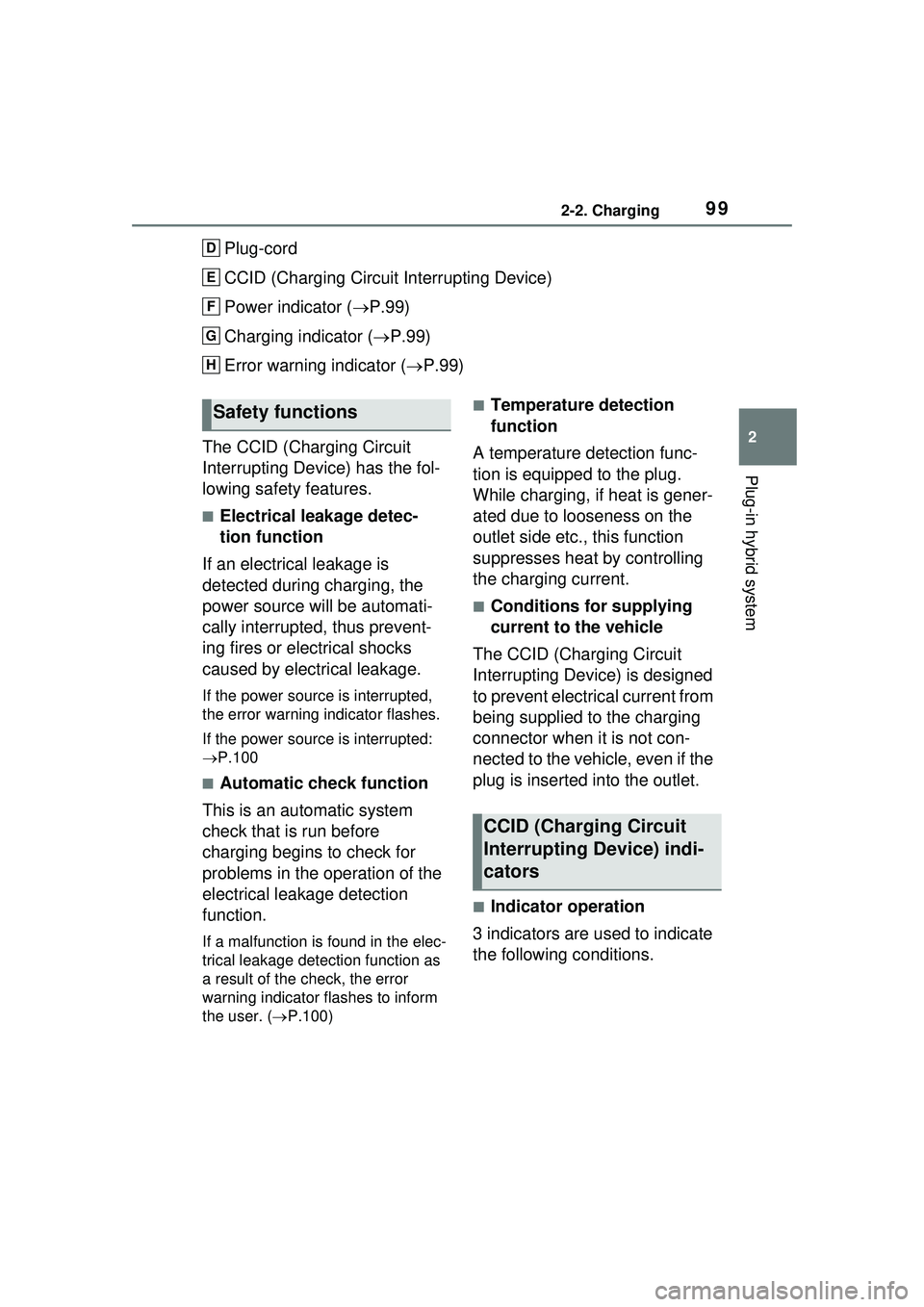
Plug-cord
CCID (Charging Circuit Interrupting Device)
Power indicator (P.99)
Charging indicator ( P.99)
Error warning indicator ( P.99)
The CCID (Charging Circuit
Interrupting Device) has the fol-
lowing safety features.
■Electrical leakage detec-
tion function
If an electrical leakage is
detected during charging, the
power source will be automati-
cally interrupted, thus prevent-
ing fires or electrical shocks
caused by electrical leakage.
If the power source is interrupted,
the error warning indicator flashes.
If the power source is interrupted:
P.100
■Automatic check function
This is an automatic system
check that is run before
charging begins to check for
problems in the operation of the
electrical leakage detection
function.
If a malfunction is found in the elec-
trical leakage detection function as
a result of the check, the error
warning indicator flashes to inform
the user. ( P.100)
■Temperature detection
function
A temperature detection func-
tion is equipped to the plug.
While charging, if heat is gener-
ated due to looseness on the
outlet side etc., this function
suppresses heat by controlling
the charging current.
■Conditions for supplying
current to the vehicle
The CCID (Charging Circuit
Interrupting Device) is designed
to prevent electrical current from
being supplied to the charging
connector when it is not con-
nected to the vehicle, even if the
plug is inserted into the outlet.
■Indicator operation
3 indicators are used to indicate
the following conditions.
D
E
F
G
H
Safety functions
CCID (Charging Circuit
Interrupting Device) indi-
cators
Page 100 of 680
1002-2. Charging
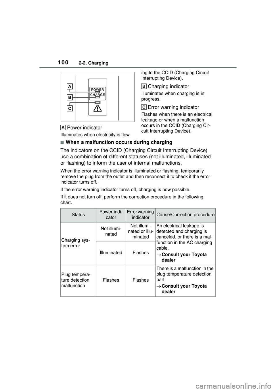
Power indicator
Illuminates when electricity is flow-ing to the CCID (C
harging Circuit
Interrupting Device).
Charging indicator
Illuminates when charging is in
progress.
Error warning indicator
Flashes when there is an electrical
leakage or when a malfunction
occurs in the CCI D (Charging Cir-
cuit Interrupting Device).
■When a malfunction occurs during charging
The indicators on the CCID (Chargi ng Circuit Interrupting Device)
use a combination of different statuses (not illuminated, illuminated
or flashing) to inform the user of internal malfunctions.
When the error warning indicator is illuminated or flashing, temporarily
remove the plug from the outlet and th en reconnect it to check if the error
indicator turns off.
If the error warning indicator turns off, charging is now possible.
If it does not turn off, perform the correction procedure in the following
chart.
A
B
C
StatusPower indi- catorError warning indicatorCause/Correction procedure
Charging sys-
tem error
Not illumi-natedNot illumi-
nated or illu- minatedAn electrical leakage is
detected and charging is
canceled, or there is a mal-
function in the AC charging
cable.
Consult your Toyota
dealer
IlluminatedFlashes
Plug tempera-
ture detection
malfunction
FlashesFlashes
There is a malfunction in the
plug temperature detection
part.
Consult your Toyota
dealer
Page 101 of 680
1012-2. Charging
2
Plug-in hybrid system
For safety, inspect the AC
charging cable on a routine
basis.
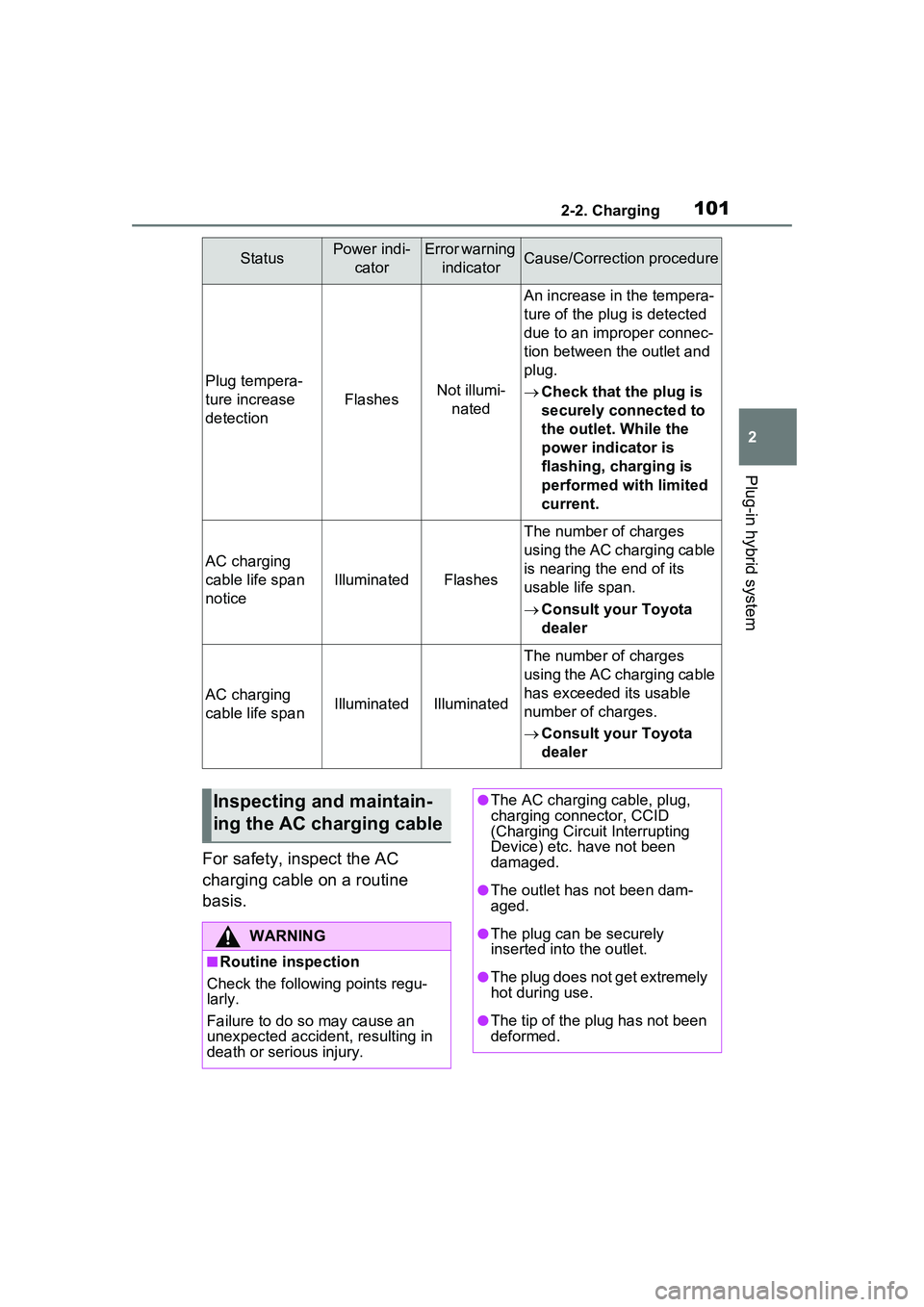
Plug tempera-
ture increase
detection
FlashesNot illumi-nated
An increase in the tempera-
ture of the plug is detected
due to an improper connec-
tion between the outlet and
plug.
Check that the plug is
securely connected to
the outlet. While the
power indicator is
flashing, charging is
performed with limited
current.
AC charging
cable life span
notice
IlluminatedFlashes
The number of charges
using the AC charging cable
is nearing the end of its
usable life span.
Consult your Toyota
dealer
AC charging
cable life spanIlluminatedIlluminated
The number of charges
using the AC charging cable
has exceeded its usable
number of charges.
Consult your Toyota
dealer
StatusPower indi-
catorError warning indicatorCause/Correction procedure
Inspecting and maintain-
ing the AC charging cable
WARNING
■Routine inspection
Check the following points regu-
larly.
Failure to do so may cause an
unexpected accident, resulting in
death or serious injury.
●The AC charging cable, plug,
charging connector, CCID
(Charging Circuit Interrupting
Device) etc. have not been
damaged.
●The outlet has not been dam-
aged.
●The plug can be securely
inserted into the outlet.
●The plug does not get extremely
hot during use.
●The tip of the plug has not been
deformed.
Page 106 of 680
1062-2. Charging
Connect to an AC 120 V out-
let (NEMA 5-15R) with a
Ground-Fault Circuit-Inter-
rupter (GFCI) and a circuit
breaker. Use of a 15A individ-
ual circuit is strongly recom-
mended to ensure AC
charging cable will operate
properly.
When charging outdoors,
make sure to connect to a
weatherproof outlet that is
certified for outdoor use.
Checking Ground-Fault Cir-
cuit-Interrupter (GFCI) opera-
tion before its use is
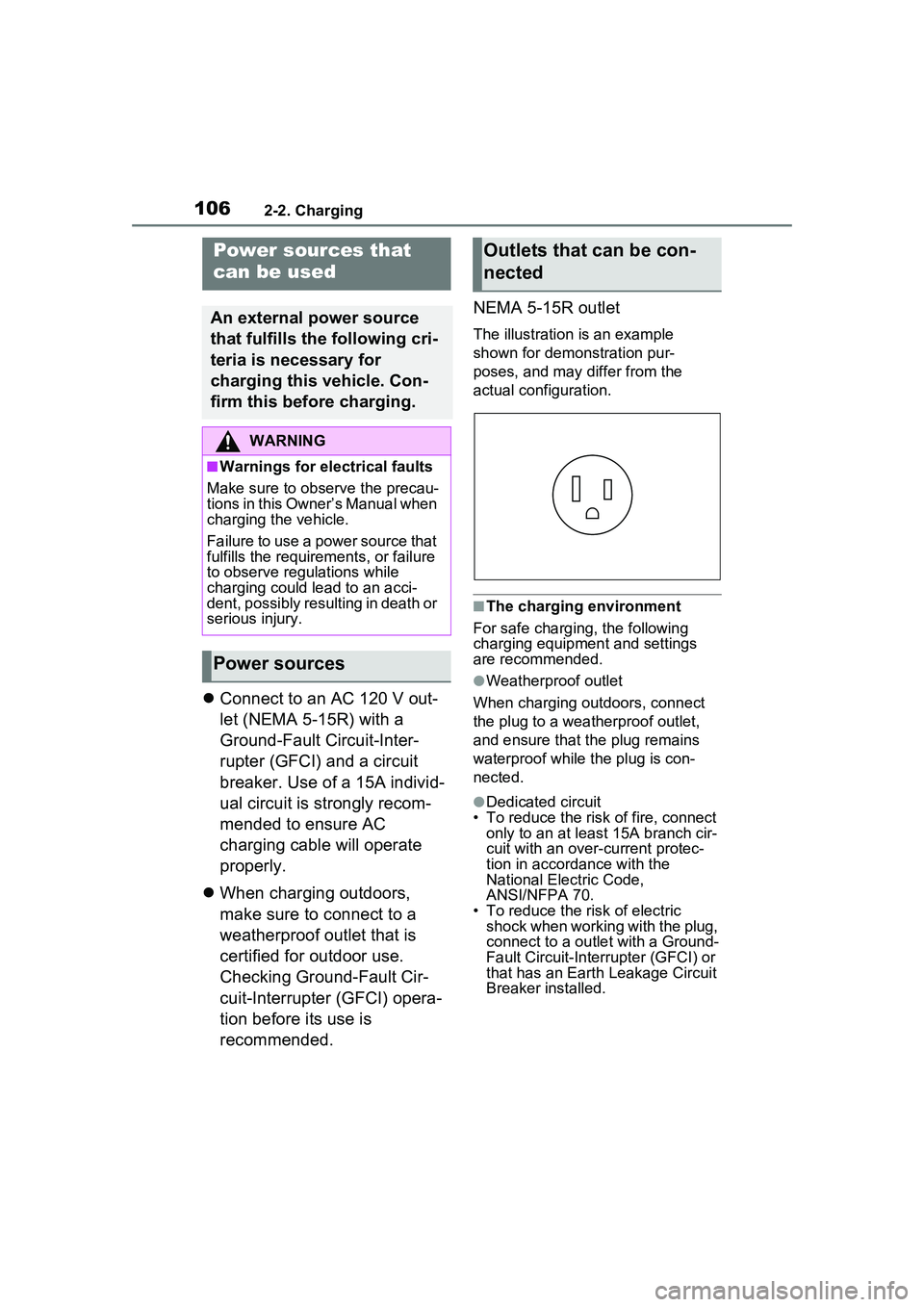
recommended. NEMA 5-15R outlet
The illustration is an example
shown for demonstration pur-
poses, and may differ from the
actual configuration.
■The charging environment
For safe charging, the following
charging equipment and settings
are recommended.
●Weatherproof outlet
When charging outdoors, connect
the plug to a weatherproof outlet,
and ensure that the plug remains
waterproof while the plug is con-
nected.
●Dedicated circuit
• To reduce the risk of fire, connect
only to an at least 15A branch cir-
cuit with an over-current protec-
tion in accordance with the
National Electric Code,
ANSI/NFPA 70.
• To reduce the risk of electric
shock when working with the plug,
connect to a outlet with a Ground-
Fault Circuit-Interr upter (GFCI) or
that has an Earth Leakage Circuit
Breaker installed.
Power sources that
can be used
An external power source
that fulfills the following cri-
teria is necessary for
charging this vehicle. Con-
firm this before charging.
WARNING
■Warnings for electrical faults
Make sure to observe the precau-
tions in this Owner’s Manual when
charging the vehicle.
Failure to use a power source that
fulfills the requirements, or failure
to observe regulations while
charging could lead to an acci-
dent, possibly resulting in death or
serious injury.
Power sources
Outlets that can be con-
nected
Page 107 of 680
1072-2. Charging
2
Plug-in hybrid system
WARNING
■Power sources precautions
Observe the following precau-
tions.
If you do not follow them, fire,
electrical shock or damage may
occur, possibly resulting in death
or serious injury.
●Connect to an AC 120 V outlet
(NEMA 5-15R) with a Ground-
Fault Circuit-Interrupter (GFCI)
and supplied by a circuit
breaker per your local code.
Use of a 15A individual circuit is
strongly recommended.
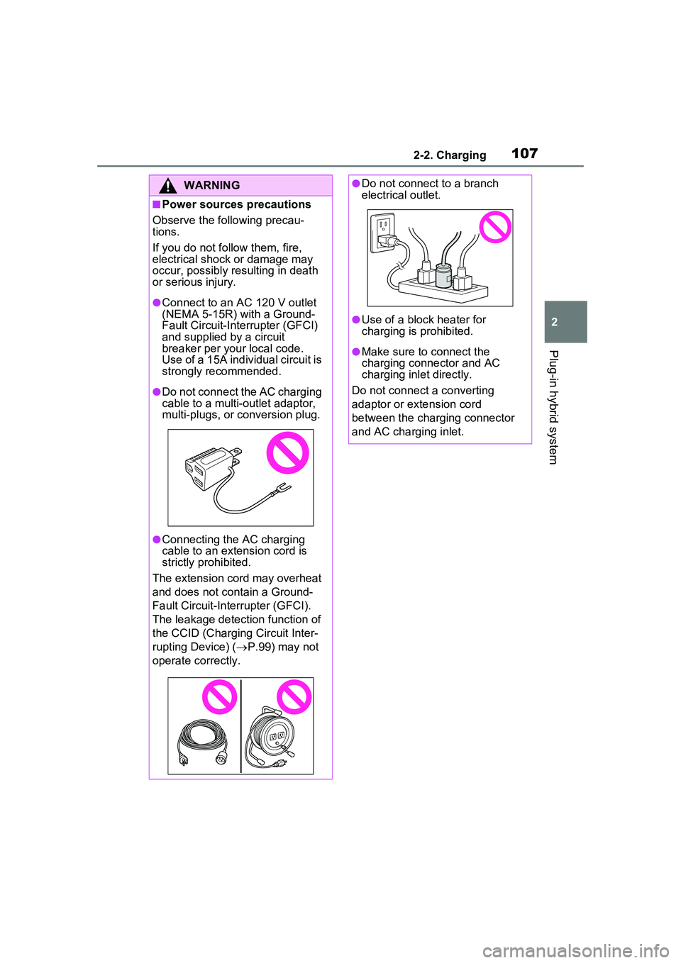
●Do not connect the AC charging
cable to a multi-outlet adaptor,
multi-plugs, or conversion plug.
●Connecting the AC charging
cable to an extension cord is
strictly prohibited.
The extension cord may overheat
and does not contain a Ground-
Fault Circuit-Inte rrupter (GFCI).
The leakage detection function of
the CCID (Charging Circuit Inter-
rupting Device) ( P.99) may not
operate correctly.
●Do not connect to a branch
electrical outlet.
●Use of a block heater for
charging is prohibited.
●Make sure to connect the
charging connector and AC
charging inlet directly.
Do not connect a converting
adaptor or extension cord
between the charging connector
and AC charging inlet.
Page 114 of 680
1142-2. Charging
Also, if the hybrid battery (traction
battery) capacity reduces, the dis-
tance that can be driven in EV mode
or AUTO EV/HV mode decreases.
However, vehicle performance does
not significantly become worse.
■When the remaining charge of
the hybrid battery (traction bat-
tery) is low after charging
In the following situations, the
remaining charge of the hybrid bat-
tery (traction battery) after charging
completes may be less than normal
in order to protect the system (the
EV driving range after the hybrid
battery [traction battery] is fully
charged may be shorter).
*
●Charging is carried out when the
outside temperature is low or high.
●Charging is carried out immedi-
ately after high-load driving or in
extreme heat.
When none of the above situations
apply and there is a drastic drop in
the remaining charge of the hybrid
battery (traction battery) after
charging completes, have the vehi-
cle inspected by your Toyota dealer.
*: When this occurs, even if the remaining charge display of the
hybrid battery (traction battery)
shows that it is fully charged, the
remaining charge rapidly
decreases faster than normal.
■When the charging amount sent
to the hybrid battery (traction
battery) decreases
When the amount of power supplied
by the charger is low or operation of
the “Battery Heater”, etc., reduces
the charging power sent to the
hybrid battery (traction battery), the
charging amount sent to the hybrid
battery (traction battery) may
decrease.
■Certification
This device complies with Part 15 of
the FCC Rules. Operation is subject to the following two conditions:
(1) this device may not cause harm-
ful interference, and
(2) this device must accept any
interference received, including
interference that may cause unde-
sired operation.
■Charging time may increase
In the following si tuations, charging
time may become longer than nor-
mal:
●In very hot or very cold tempera-
tures.
●When the hybrid battery (traction
battery) becomes hot, such as
immediately after high-load driv-
ing.
●The vehicle is consuming a lot of
electricity, for example, when the
headlights are on etc.
●When using “My Room Mode”.
( P.134)
●There is a power outage during
charging.
●There is an interruption in the
electrical supply.
●There is a drop in the voltage of
external power source.
●The charge in the 12-volt battery
is low, for example due to the
vehicle being left unused for a
long period of time.
●When the upper limit of charging
current is changed in the charging
current setting of the vehicle.
( P.119)
●When the “Battery Heater” oper-
ates. ( P.108)
●When the “Battery Cooler” is oper-
ated before charging. ( P.109)
●When the plug generates heat
due to a loose outlet connection
etc.
●When the temperature of
charging-related parts is high.
Page 117 of 680
1172-2. Charging
2
Plug-in hybrid system
P.115
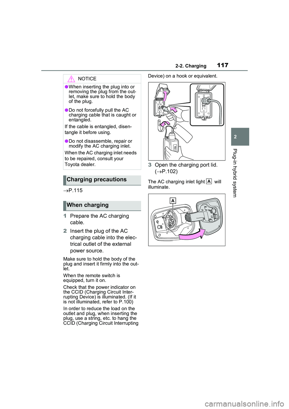
1 Prepare the AC charging
cable.
2 Insert the plug of the AC
charging cable into the elec-
trical outlet of the external
power source.
Make sure to hold the body of the
plug and insert it firmly into the out-
let.
When the remote switch is
equipped, turn it on.
Check that the power indicator on
the CCID (Charging Circuit Inter-
rupting Device) is illuminated. (If it
is not illuminated, refer to P.100)
In order to reduce the load on the
outlet and plug, when inserting the
plug, use a string, etc. to hang the
CCID (Charging Circ uit Interrupting Device) on a hook or equivalent.
3
Open the charging port lid.
( P.102)
The AC charging inlet light will
illuminate.
NOTICE
●When inserting the plug into or
removing the plug from the out-
let, make sure to hold the body
of the plug.
●Do not forcefully pull the AC
charging cable that is caught or
entangled.
If the cable is entangled, disen-
tangle it before using.
●Do not disassemble, repair or
modify the AC charging inlet.
When the AC charging inlet needs
to be repaired, consult your
Toyota dealer.
Charging precautions
When charging
A