key TOYOTA RAV4 1996 Service Service Manual
[x] Cancel search | Manufacturer: TOYOTA, Model Year: 1996, Model line: RAV4, Model: TOYOTA RAV4 1996Pages: 1632, PDF Size: 41.64 MB
Page 1240 of 1632
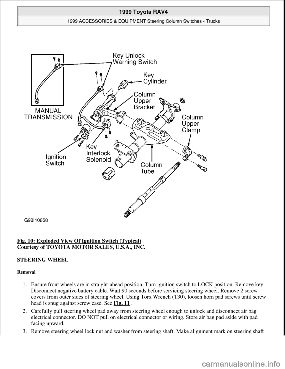
Fig. 10: Exploded View Of Ignition Switch (Typical)
Courtesy of TOYOTA MOTOR SALES, U.S.A., INC.
STEERING WHEEL
Removal
1. Ensure front wheels are in straight-ahead position. Turn ignition switch to LOCK position. Remove key.
Disconnect negative battery cable. Wait 90 seconds before servicing steering wheel. Remove 2 screw
covers from outer sides of steering wheel. Using Torx Wrench (T30), loosen horn pad screws until screw
head is snug against screw case. See Fig. 11
.
2. Carefully pull steering wheel pad away from steering wheel enough to unlock and disconnect air bag
electrical connector. DO NOT pull on electrical connector or wiring. Store air bag pad aside with pad
facing upward.
3. Remove steerin
g wheel lock nut and washer from steering shaft. Make alignment mark on steering shaft
1999 Toyota RAV4
1999 ACCESSORIES & EQUIPMENT Steering Column Switches - Trucks
Microsoft
Sunday, November 22, 2009 10:56:55 AMPage 12 © 2005 Mitchell Repair Information Company, LLC.
Page 1259 of 1632
Fig. 2: Removing Steering Wheel Pad (Typical)
Courtesy of TOYOTA MOTOR SALES, U.S.A., INC.
3. Remove lock nut and washer. Mark steering shaft and steering wheel for installation reference. Install
steering wheel puller, and remove steering wheel from shaft.
4. Prior to installation, ensure spiral cable (located on combination switch) is properly aligned. See SPIRAL
CABLE under ADJUSTMENTS. To complete installation, reverse removal procedure. Tighten steering
wheel nut to specification. See TORQUE SPECIFICATIONS
.
COMBINATION SWITCH
Removal & Installation
1. Disconnect negative battery cable. Remove steering wheel. See STEERING WHEEL & HORN PAD
or STEERING WHEEL & AIR BAG
. Remove instrument cluster lower finish panel. Remove upper
and lower steering column covers.
2. Disconnect combination switch electrical connectors and air bag connector. Remove combination switch
mounting screws, and remove combination switch. To install, reverse removal procedure. Tighten
steering wheel nut to specification. See TORQUE SPECIFICATIONS
.
IGNITION SWITCH & LOCK CYLINDER
Removal & Installation
1. Disconnect negative battery cable. Remove steering wheel, upper and lower steering column covers and
combination switch (if necessary).
2. Place ignition key at ACC position. Using screwdriver, push down stop pin of cylinder, and pull out lock
cylinder. Remove 2 screws and ignition switch.
3. To install, reverse removal procedure. Install combination switch, upper and lower steering column
covers and steering wheel. Tighten steering wheel nut to specification. See TORQUE
SPECIFICATIONS .
STEERING COLUMN
Removal & Installation (Land Cruiser)
1. Disconnect negative battery cable. Remove steering wheel. See STEERING WHEEL & HORN PAD
or STEERING WHEEL & AIR BAG
. Remove steering column upper and lower covers. See Fig. 4 .
Remove combination switch with spiral cable.
2. Remove scuff plate and cowl trim. Remove cluster finish panel. Remove lower No. 1 panel and left-side
lower panel. Remove No. 2 heater- to- register duct from under steering column.
3. Mark intermediate shaft and control valve shaft for installation reference. Loosen bolt "A", and remove
bolts "B" and "C". See Fig. 3
. Disconnect No. 2 intermediate shaft assembly. Remove No. 2 intermediate
shaft assembl
y. Remove hole cover.
1999 Toyota RAV4
1999-2000 STEERING Steering Columns - Tilt Wheel - Trucks & Vans
Microsoft
Sunday, November 22, 2009 10:34:02 AMPage 5 © 2005 Mitchell Repair Information Company, LLC.
Page 1266 of 1632
1. Insert column hole cover No. 2. Align match marks on column assembly and No. 2 "U" joint assembly.
Install bolt to connect No. 2 "U" joint assembly.
2. Install column assembly with No. 2 "U" joint assembly. Install 4 steering column set nuts. Connect
connectors. On models equipped with A/T, connect transmission control cable assembly to shift lever
assembly.
3. Align match marks on No. 2 "U" joint assembly and No. 2 intermediate shaft assembly. Align match
marks on control valve shaft and No. 2 intermediate shaft assembly. Install "A" and "B" bolts.
4. Install brake pedal return spring and No. 2 heater to register duct. Install lower finish panel with 4 bolts.
Connect hood lock release lever with 2 screws. Install spiral cable. See SPIRAL CABLE
under
ADJUSTMENTS. Install combination switch with 3 screws. Connect air bag and connectors.
5. Install lower and upper column covers with 3 screws. Ensure tires are in straight-ahead position. Turn
cable counterclockwise until there is resistance. Rotate cable clockwise 2.5 turns to align mark.
6. To install steering wheel, align match marks on wheel and main shaft. Install wheel set nut. Connect
connector. Install steering wheel pad. Connect air bag connector. Install wheel pad when Torx screw is
set in screw case. Using a Torx socket wrench, torque 2 screws to 78 INCH lbs. (8.8 N.m). Install 2
steering wheel lower No. 2 covers. Check steering wheel center point.
7. Tighten all bolts to specifications. See TORQUE SPECIFICATIONS
. Ensure spiral cable is properly
installed and adjusted. See SPIRAL CABLE
under ADJUSTMENTS.
Removal & Installation (4Runner)
1. Disconnect negative battery cable. Remove steering wheel. See STEERING WHEEL & AIR BAG .
Remove upper and lower column covers. See Fig. 4
. Remove left-side lower finish panel. Remove starter
switch bezel. Remove No. 2 heater to register duct from under steering column.
2. Remove combination switch with spiral cable. Remove spiral cable. Remove brake pedal return spring.
Mark intermediate shaft No. 2, "U" joints No. 2 and control valve for installation reference. Remove
intermediate shaft No. 2 and bolts. Remove column hole cover and column hole cover No. 2 set bolt.
3. Remove steering column assembly with "U" joint No. 2. Disconnect "U" joint No. 2. To install, reverse
removal procedure. Tighten bolts and nuts to specification. See TORQUE SPECIFICATIONS
.
OVERHAUL
STEERING COLUMN
Disassembly (Land Cruiser)
1. Remove No. 2 lower cover. Mark shaft assembly and main shaft assembly for reassembly reference.
Remove intermediate shaft assembly. See Fig. 6
. Remove transponder key coil with key cylinder lamp
assembly. Remove key cylinder lamp assembly.
1999 Toyota RAV4
1999-2000 STEERING Steering Columns - Tilt Wheel - Trucks & Vans
Microsoft
Sunday, November 22, 2009 10:34:02 AMPage 12 © 2005 Mitchell Repair Information Company, LLC.
Page 1271 of 1632
Check that lock mechanism operates properly. Check bearing rotation condition and check for abnormal noise.
Repair or replace components as necessary.
Reassembly
To reassemble, reverse disassembly procedure using NEW thrust collar. Align bushing tab with hole of column
tube. Apply molybdenum disulfide lithium base grease to tilt lever assembly, main shaft, column bushing, thrust
collar, bearing and steering column bolt pivot points. Tighten bolts and nuts to specification. See TORQUE
SPECIFICATIONS .
Disassembly (Sienna)
1. Remove ignition key cylinder illumination. See Fig. 9 . Using 1/8-5/32" (3-4 mm) drill, drill tapered head
column bracket bolts. Using screw extractor, remove bracket bolts. Remove column upper bracket and
column upper clamp. Remove shift lever.
1999 Toyota RAV4
1999-2000 STEERING Steering Columns - Tilt Wheel - Trucks & Vans
Microsoft
Sunday, November 22, 2009 10:34:03 AMPage 17 © 2005 Mitchell Repair Information Company, LLC.
Page 1274 of 1632
SPECIFICATIONS .
Disassembly (Tacoma & 4Runner)
1. On 4 Runner, remove screw and transponder key coil with key cylinder lamp assembly. On all models,
use screw extractor to remove steering column upper bracket bolts. Remove column upper bracket and
column upper clamp. See Fig. 11
and Fig. 12 .
2. On 4 Runner, remove 3 tension springs. On Tacoma remove 4 tension springs. On all models, using
screwdriver, remove spring nut. Remove lever and 2 bushings from column upper tube. Remove tilt lever
link. On all models except Tacoma (NASTECH), remove column upper tube with main shaft. See Fig.
12 .
3. Using snap ring expander, remove snap ring from shaft. Using plastic hammer, tap out shaft from column
tube. Remove compression ring from shaft. Using pinch punch and hammer, tap out tilt steering No. 2
shaft. Remove pawl from column upper tube. Remove pin from pawl. On Tacoma, remove turn signal
bracket and column shift lever assembly from column shift.
1999 Toyota RAV4
1999-2000 STEERING Steering Columns - Tilt Wheel - Trucks & Vans
Microsoft
Sunday, November 22, 2009 10:34:03 AMPage 20 © 2005 Mitchell Repair Information Company, LLC.
Page 1277 of 1632
Courtesy of TOYOTA MOTOR SALES, U.S.A., INC.
Inspection
Check that lock mechanism operates properly. Check bearing rotation condition and check for abnormal noise.
Check bearing rotation condition of main shaft assembly and check for abnormal noise. Repair or replace
components as necessary.
Reassembly
To reassemble, reverse disassembly procedure. Align bushing tab with hole of column tube. Apply
molybdenum disulfide lithium base grease to tilt lever assembly, lock bolt, main shaft and steering column bolt
pivot points. Tighten bolts and nuts to specification. See TORQUE SPECIFICATIONS .
Disassembly (Tundra)
1. Place steering column assembly in vise. Remove clip and key cylinder lamp assembly. Using punch,
mark center of 2 tapered-head bolts. Drill out 2 bolts. Remove 2 bolts, using screw extractor. Remove
column upper bracket and column upper clamp. On models equipped with A/T, remove shift lever, upper
No. 2 steering cover, park lock cable assembly and shift lever housing.
2. On all models, remove release lever spring and turn signal bracket. To remove steering column housing
with main shaft on models equipped with tilt steering, install plate washers (18 and 36-mm outer
diameter) and screw (4-mm diameter, .7-mm pitch, 15-mm length). See Fig. 10
. Remove column
housing with shaft assembly from column tube assembly. Remove tilt spring and spring guide.
3. On models equipped with A/T, remove 4 Torx bolts, 2 tilt No. 1 stoppers and steering column housing
support. On all models, remove bolt and washer and remove column tube support with lower column tube
attachment. Remove lower column tube attachment from column tube support.
4. Remove main shaft stopper and assembly. Ensure shaft assembly does not rotate. Using screwdriver,
remove retaining ring. Remove spring retainer, compression spring, upper bearing inner race and inner
race.
Inspection
Ensure lock mechanism, key cylinder, ignition switch and key unlock warning switch operate properly. Check
column bearing for rotating smoothness. Replace column housing if bearing or housing shows any damage.
Check steering shaft for bends, damaged splines or damaged "U" joints. Repair or replace components as
necessary.
Reassembly
1. Install inner race, upper bearing inner race seat, compression spring and spring retainer. Install NEW
retaining ring to main shaft assembly. Install retaining ring remover/replacer to main shaft assembly.
Using retaining ring remover/replacer, push down retaining ring until ring fits into shaft groove. Install
main shaft assembly.
2. Ensure main shaft assembly does not rotate. Install main shaft stopper. Install NEW lower column tube
attachment, bolt and washer to column tube support.
1999 Toyota RAV4
1999-2000 STEERING Steering Columns - Tilt Wheel - Trucks & Vans
Microsoft
Sunday, November 22, 2009 10:34:03 AMPage 23 © 2005 Mitchell Repair Information Company, LLC.
Page 1454 of 1632
1. Ensure all power window modes function normally (i.e., UP, DOWN, AUTO UP, AUTO DOWN and
key OFF). If all modes function normally, go to next step. If all modes do not function normally, perform
appropriate symptom test.
2. AUTO REVERSE should operate when there is resistance to power window motor while raising window.
If window opening is greater than 7.874" (200 mm) when window glass travel is obstructed, window will
automatically lower 1.969" (50 mm) and stop. If window opening is 7.874" (200 mm) or less when
window glass travel is obstructed, window will automatically lower until opening is 7.874" (200 mm) and
stop. If operation is as specified, system is okay at this time. If operation is not as specified, go to next
step.
3. Check power window motor limit switches for proper adjustment. See ADJUSTING METHOD FOR
JAM PROTECTION under ADJUSTMENTS. Ensure power window motor is installed correctly. If
motor is installed correctly and AUTO REVERSE still does not operate as specified, replace power
window master switch or power window control switch.
ONE-TOUCH POWER WINDOW IS INOPERATIVE
1. Turn ignition switch to ON position and toggle power window master switch to UP or DOWN position
for driver's side window only. Ensure power window master switch AUTO light begins to flash fault
code. See Fig. 1
. For Fault Code 1, go to next step. For Fault Code 2 or 3, go to step 3 . If AUTO light
does not stay illuminated after 30 seconds, or flashes stop after ignition switch is turned to OFF position,
replace power window master switch.
2. Fault Code 1 occurs when there is an error in power window motor limit switch. Remove power window
master switch from door panel, with connector attached. Measure voltage by backprobing between power
window master switch connector terminals No. 1 and 5. Voltage should change from zero volts when
window is fully closed, to 10-14 volts while window is opening. If voltage is not as specified, go to next
step. If voltage is as specified, replace power window master switch. If AUTO UP and AUTO DOWN
does not work after power window master switch is replaced, replace power window motor.
3. Disconnect power window master switch and driver's power window motor from harness connectors.
Check continuity between appropriate power window master switch terminals and driver's power window
motor terminals. See ONE
-TOUCH POWER WINDOW TESTS table. If continuity is present at all
measurements, go to next step. If continuity is not present at any measurement, repair open circuit in
affected wire.
ONE-TOUCH POWER WINDOW TESTS NOTE: When a fault for one-touch mode in driver's power window master switch
occurs, AUTO light on power window master switch will output a flash code.
After 30 seconds, AUTO light will stop flashing and will stay on. If ignition
switch is turned to OFF position during flash mode, flashing will stop.
ModelCheck Between Master Switch Terminal
No. & (Driver's Window Motor Terminal
No.)
Land Cruiser
(1) 1 & (4)
1999 Toyota RAV4
1999-2000 ACCESSORIES & EQUIPMENT Power Windows - Trucks
Microsoft
Sunday, November 22, 2009 10:59:35 AMPage 2 © 2005 Mitchell Repair Information Company, LLC.
Page 1518 of 1632
Remove wiper arm. Remove back door assist grip. Remove pull strap. Remove center garnish above rear door
window by prying along window edge. Remove side garnish on each side of window by pulling inward to
release clips. Pull rear door trim panel outward and remove. Disconnect rear wiper motor connector and remove
bolts attaching rear wiper motor and linkage to rear door.
Removal (4Runner)
Remove back door trim panel. Remove plate and back door glass run channel. Remove outer weatherstrip and
remove rear window. Remove wiper arm and wiper shaft nut on outside of door. Disconnect electrical
connector, remove 3 bolts and remove wiper motor assembly.
Installation (All Models)
To install, reverse removal procedure. Adjust wiper blades to appropriate position. See ADJUSTMENTS .
REAR WIPER SWITCH
Removal & Installation
Switch is integral part of wiper switch mounted to combination switch on steering column. See FRONT
WIPER SWITCH .
STEERING WHEEL
Removal
1. Ensure front wheels are in straight-ahead position. Place ignition switch in LOCK position and remove
key. Disconnect negative battery cable. Remove 2 screw covers from outer sides of steering wheel. Using
Torx Wrench (T30), loosen air bag pad retaining Torx screws until screw heads are snug against screw
case. See Fig. 15
.
2. Carefully pull air bag pad away from steering wheel enough to unlock and disconnect air bag electrical
connector. DO NOT pull on electrical connector or wiring. Store air bag pad aside with pad facing
upward.
3. Remove steering wheel lock nut and washer from steering shaft. Make alignment mark on steering shaft
and steering wheel for installation reference. Using appropriate steering wheel puller, pull steering wheel
from shaft while guiding spiral cable wire through steering wheel opening.
Installation
1. Ensure front wheels are in straight-ahead position. Connect and install spiral cable to combination switch.
Turn spiral cable counterclockwise by hand until it is hard to turn. Turn spiral cable clockwise about 2
1/2-3 turns and align Red mark at bottom with opening.
2. Guide spiral cable through steering wheel opening while installing steering wheel to shaft. Align
reference marks on steering shaft and steering wheel. Install steering wheel lock nut and washer. Tighten
steering wheel lock nut to 25 ft. lbs. (34 N.m).
3. Connect air bag electrical connector and snap down connector lock. Before installing air bag pad, ensure
Torx screws are retracted and snu
g against screw case. See Fig. 15.
1999 Toyota RAV4
1999-2000 ACCESSORIES & EQUIPMENT Wiper/Washer Systems
Microsoft
Sunday, November 22, 2009 11:01:20 AMPage 23 © 2005 Mitchell Repair Information Company, LLC.