heater TOYOTA RAV4 1996 Service Repair Manual
[x] Cancel search | Manufacturer: TOYOTA, Model Year: 1996, Model line: RAV4, Model: TOYOTA RAV4 1996Pages: 1632, PDF Size: 41.64 MB
Page 45 of 1632
1. Before proceeding, see SERVICE PRECAUTIONS . Disable SRS. See DISABLING &
ACTIVATING AIR BAG SYSTEM .
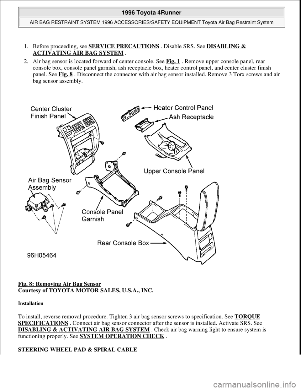
2. Air bag sensor is located forward of center console. See Fig. 1
. Remove upper console panel, rear
console box, console panel garnish, ash receptacle box, heater control panel, and center cluster finish
panel. See Fig. 8
. Disconnect the connector with air bag sensor installed. Remove 3 Torx screws and air
bag sensor assembly.
Fig. 8: Removing Air Bag Sensor
Courtesy of TOYOTA MOTOR SALES, U.S.A., INC.
Installation
To install, reverse removal procedure. Tighten 3 air bag sensor screws to specification. See TORQUE
SPECIFICATIONS . Connect air bag sensor connector after the sensor is installed. Activate SRS. See
DISABLING & ACTIVATING AIR BAG SYSTEM
. Check air bag warning light to ensure system is
functioning properly. See SYSTEM OPERATION CHECK
.
STEERING WHEEL PAD & SPIRAL CABLE
1996 Toyota 4Runner
AIR BAG RESTRAINT SYSTEM 1996 ACCESSORIES/SAFETY EQUIPMENT Toyota Air Bag Restraint System
Microsoft
Tuesday, August 18, 2009 7:33:32 PMPage 11 © 2005 Mitchell Repair Information Company, LLC.
Page 46 of 1632
Removal
1. Before proceeding, follow air bag service precautions. See SERVICE PRECAUTIONS . Ensure front
wheels are in a straight-ahead position. Turn ignition switch to LOCK position. Disconnect and shield
negative battery cable. Wait at least 90 seconds before working on system.
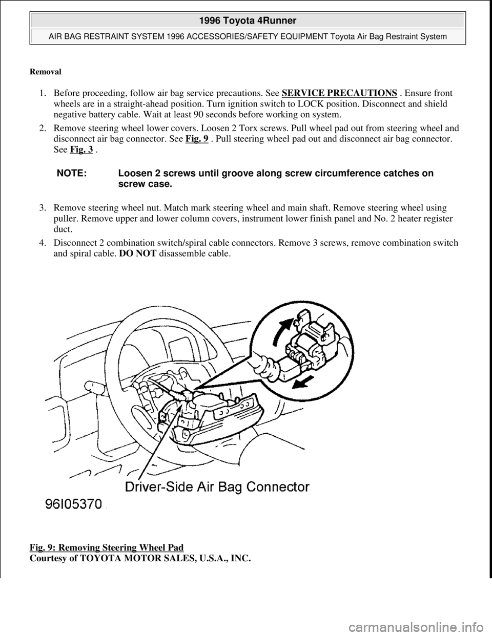
2. Remove steering wheel lower covers. Loosen 2 Torx screws. Pull wheel pad out from steering wheel and
disconnect air bag connector. See Fig. 9
. Pull steering wheel pad out and disconnect air bag connector.
See Fig. 3
.
3. Remove steering wheel nut. Match mark steering wheel and main shaft. Remove steering wheel using
puller. Remove upper and lower column covers, instrument lower finish panel and No. 2 heater register
duct.
4. Disconnect 2 combination switch/spiral cable connectors. Remove 3 screws, remove combination switch
and spiral cable. DO NOT disassemble cable.
Fig. 9: Removing Steering Wheel Pad
Courtesy of TOYOTA MOTOR SALES, U.S.A., INC. NOTE: Loosen 2 screws until groove along screw circumference catches on
screw case.
1996 Toyota 4Runner
AIR BAG RESTRAINT SYSTEM 1996 ACCESSORIES/SAFETY EQUIPMENT Toyota Air Bag Restraint System
Microsoft
Tuesday, August 18, 2009 7:33:32 PMPage 12 © 2005 Mitchell Repair Information Company, LLC.
Page 56 of 1632
3. With squib circuit connector disconnected, insert paper into female terminal, sliding it under shorting bar
spring. This lifts the spring, breaking the circuit and allowing the test procedure to be performed as
specified.
TESTING - DIAGNOSTIC
NO CODES - SOURCE VOLTAGE DROP
1. Disconnect negative battery cable. Wait at least 90 seconds. Remove steering wheel pad. See
STEERING WHEEL PAD & SPIRAL CABLE
under REMOVAL & INSTALLATION. Disconnect
passenger-side air bag harness connector, accessible through finish plate in glove box. See Fig. 2
.
Disconnect air bag sensor assembly connector.
2. Reconnect negative battery cable. Turn ignition switch to ON position. Measure voltage between ground
and terminals IG2 and ACC of air bag sensor connector. See Fig. 13
. Operate electrical components
(defogger, wiper, headlights, heater blower, etc.). If voltage is 8-14 volts, go to next step. If voltage is not
8-14 volts, check harness between battery and air bag sensor assembly and check battery and charging
system.
3. Turn ignition switch to LOCK position. Connect steering wheel pad connector. Connect passenger-side
air bag connector. Turn ignition switch to ON position. Operate electrical components as in step 2) and
check that SRS warning light goes off. If light does not go off, check diagnostic trouble code and go to
appropriate CODE under TESTING - DIAGNOSTIC. If a normal code is output, replace air bag sensor
assembly. If warning light goes off, no problem detected at this time.
CODE 11
1. Disconnect negative battery cable. Wait at least 90 seconds. Remove steering wheel pad. See
STEERING WHEEL PAD & SPIRAL CABLE
under REMOVAL & INSTALLATION. Disconnect
passenger-side air bag harness connector, accessible through finish plate in glove box. See Fig. 2
.
Disconnect air bag sensor assembly connector.
2. Measure resistance on spiral cable side of connector between spiral cable and steering wheel pad between
D+, D- and ground. If resistance is 1000 ohms or more, go to next step. If resistance is less than 1000
ohms, go to step 7).
3. Measure resistance on air ba
g sensor assembly side of connector between air bag sensor and passenger- WARNING:Paper must not be thicker than male terminal. If paper is thicker,
connector terminal may be damaged, possible resulting in system
fault.
NOTE: Use Diagnosis Check Wiring (09843-18020) when connecting jumper wire
between terminals of DLC. Spiral cable upper connector is same as steering
wheel pad (squib) connector. Spiral cable lower connector (located under
steering column) connects the harness between spiral cable and center air bag
sensor.
NOTE: During testing, if codes other than Code 11 are displayed, disregard them.
1996 Toyota 4Runner
AIR BAG RESTRAINT SYSTEM 1996 ACCESSORIES/SAFETY EQUIPMENT Toyota Air Bag Restraint System
Microsoft
Tuesday, August 18, 2009 7:33:32 PMPage 22 © 2005 Mitchell Repair Information Company, LLC.
Page 80 of 1632
INSTRUMENT PANEL
Removal & Installation
1. Before proceeding, see SERVICE PRECAUTIONS . Turn ignition switch to LOCK position.
Disconnect negative battery cable. Wait at least 90 seconds.
2. Access and disconnect right and left seat belt pretensioner connectors. See SEAT BELT
PRETENSIONERS . Remove front door scuff plates and cowl side trim boards. See Fig. 13 . Remove
steering wheel. See STEERING WHEEL
. Remove steering column covers and cluster finish panel.
Remove instrument cluster. Remove hood lock release lever.
3. Remove lower finish panel and instrument panel lower insert. Remove No. 2 heater-to-register duct.
Remove steering column assembly. See STEERING COLUMN
. Remove 2 screws and center cluster
finish panel. Pull off heater control knobs and pry off heater control name plate. Pry off cluster instrument
panel, then remove 3 screws from heater control assembly. Disconnect connectors and remove cluster
instrument panel.
4. Disconnect control cables and remove heater control assembly. Remove radio assembly. Remove console
box. Tape tip of screwdriver and remove lower center cluster finish panel. Disconnect connectors.
Remove stereo opening cover. Remove glove box assembly. Remove side trim cover. Disconnect
remaining connectors and remove bolts, then remove instrument panel.
5. To install, reverse removal procedure. Tighten fasteners to specification. See TORQUE
SPECIFICATIONS . Check AIR BAG warning light to ensure system is functioning properly. See
SYSTEM OPERATION CHECK
.
1999 Toyota RAV4
AIR BAG RESTRAINT SYSTEM 1999 Toyota
Microsoft
Sunday, November 22, 2009 10:33:22 AMPage 17 © 2005 Mitchell Repair Information Company, LLC.
Page 83 of 1632
1. Before proceeding, see SERVICE PRECAUTIONS . Ensure front wheels are in straight-ahead position.
Turn ignition switch to LOCK position. Disconnect negative battery cable. Wait at least 90 seconds.
Remove steering wheel. See STEERING WHEEL
.
2. Remove lower finish panel and instrument panel lower insert. Remove upper and lower steering column
covers. Disconnect and remove combination switch with spiral cable attached. Remove heater-to-register
duct. Match mark steering shaft and steering gear shaft for reassembly performance. Remove steering
column.
3. To install, reverse removal procedure. Tighten fasteners to specification. See TORQUE
SPECIFICATIONS . Check AIR BAG warning light to ensure system is functioning properly. See
SYSTEM OPERATION CHECK
.
STEERING WHEEL
Removal & Installation
1. Before proceeding, see SERVICE PRECAUTIONS . Ensure front wheels are in straight-ahead position.
Turn ignition switch to LOCK position. Disconnect negative battery cable. Wait at least 90 seconds.
Remove driver-side air bag module. See DRIVER
-SIDE AIR BAG MODULE .
2. Remove steering wheel nut. Match mark steering wheel and steering column for reassembly reference.
Using appropriate puller, remove steering wheel.
3. To install, reverse removal procedure. Ensure front wheels are in straight-ahead position and spiral cable
is properly aligned. See SPIRAL CABLE under ADJUSTMENTS
. Tighten steering wheel nut and
driver-side air bag module screws to specification. See TORQUE SPECIFICATIONS
. Check AIR
BAG warning light to ensure system is functioning properly. See SYSTEM OPERATION CHECK
.
SYSTEM OPERATION CHECK
Turn ignition switch to ACC or ON position. AIR BAG warning light should come on for about 6 seconds and
then go out. If AIR BAG warning light does not operate as specified, see DIAGNOSIS & TESTING
.
DIAGNOSIS & TESTING
AIR BAG WARNING LIGHT CHECK
Turn ignition switch to ACC or ON position. If air bag warning light comes on for about 6 seconds and then
goes off, system is functioning properly. If AIR BAG warning light comes on and stays on (or flashes),
Diagnostic Trouble Code (DTC) is stored in air bag sensor assembly. Go to RETRIEVING CODES
. If AIR
BAG warning light responds in any other way, go to DIAGNOSTIC TESTS
.
RETRIEVING CODES
CAUTION: System may be damaged if jumper wire is incorrectly connected across
terminals of Data Link Connector (DLC1). Use Diagnosis Check Wire
(09843-18020) when connecting terminals of DLC1.
1999 Toyota RAV4
AIR BAG RESTRAINT SYSTEM 1999 Toyota
Microsoft
Sunday, November 22, 2009 10:33:22 AMPage 20 © 2005 Mitchell Repair Information Company, LLC.
Page 143 of 1632
installing the remaining torque converter bolts.
5. Use NEW gasket when installing front exhaust pipe. Adjust all cables, shift linkages and fill with ATF.
See appropriate TRANSMISSION SERVICING article.
Removal (4Runner 4WD)
1. Disconnect negative battery cable. Remove rear console upper panel and disconnect electrical connectors.
Rear console upper panel is located on the top of the console, near emergency brake lever.
2. Remove heater control knobs from instrument panel. Using screwdriver, pry heater control plate from
center finish panel on instrument panel. Center finish panel is the panel that fits around the radio and air
outlet ducts, located at center of instrument panel.
3. Remove screws and disconnect electrical connectors from center finish panel from instrument panel.
Remove center finish panel.
4. On models without 2-4 selector button on side of transfer case shift lever, unscrew knob from transfer
case shift lever. On models with2-4 selector button on side of transfer case shift lever, remove screw from
knob on transfer case shift lever. Remove knob from transfer case shift lever and lay aside with wire
attached.
5. On all models, remove upper console panel which contains boot for transfer case shift lever and is located
on center console. On models with 2-4 selector button on side of transfer case shift lever, disconnect
electrical connector for 2-4 selector button and remove knob on transfer case shift lever.
6. On all models, remove screws, clips and front console box, located around transmission shift lever
assembly and transfer case shift lever. Raise and support vehicle. Disconnect shift linkage at transmission
shift lever.
7. Disconnect electrical connectors for removal of transmission shift lever assembly. Remove transmission
shift lever assembly. Remove snap ring and transfer case shift lever.
8. Remove transmission oil dipstick, dipstick tube and "O" ring. Remove lower engine covers. Place
reference marks on drive shaft flanges for reassembly reference. Remove drive shafts.
9. Remove front exhaust pipe, located between exhaust manifold and catalytic converter on rear exhaust
pipe. Disconnect and necessary electrical connectors for transmission and transfer case removal. Separate
wiring harness from transmission and transfer case.
10. Remove starter. Remove transmission oil cooler pipes and brackets as necessary. On 3.4L V6, it may be
necessary to remove stabilizer bar.
11. On all models, support transmission with floor jack. Remove rear transmission mount-to-transmission
crossmember bolts. Remove transmission crossmember, located below transmission and transfer case.
12. Remove torque converter cover from front of transmission. On 3.4L, note location of Green torque
converter bolt for re-installation reference. Remove torque converter bolts. Remove transmission-to-
cylinder block bolts. Lower transmission with transfer case from vehicle.
Installation
1. Before installing transmission, use dial indicator to check drive plate runout. Drive plate runout should be
checked right next to the starter ring gear on the drive plate. Replace drive plate if runout
exceeds .0079" (.200 mm).
2. Install torque converter on transmission. To ensure torque converter is fully seated, torque converter
1998 Toyota Avalon XLS
TRANSMISSION SERVICING - A/T 1997-98 TRANSMISSION SERVICING Toyota - Transmission Removal &
Installation
Helpmelearn
November-03-08 10:30:29 AMPage 31 © 2005 Mitchell Repair Information Company, LLC.
Page 364 of 1632
1. Disconnect fluid level warning switch connector. Remove fluid from master cylinder with syringe.
Remove 2 bolts, and move relay box aside. Remove air cleaner housing and hose.
2. Disconnect brake lines and 3-way line connector from master cylinder. If equipped with M/T, disconnect
clutch reservoir hose. On all models, remove 2 bolts and master cylinder.
3. Prior to installation, adjust length of brake booster push rod if necessary. See POWER BRAKE UNIT
PUSH ROD under ADJUSTMENTS.
4. Install master cylinder in reverse of removal procedure. Use NEW gasket. Fill and bleed system. Check
for leaks and adjust pedal, if needed. Bleed clutch system, if equipped.
Removal & Installation (Sienna)
1. Remove air cleaner assembly. Disconnect fluid level warning switch connector. Remove fluid from
master cylinder with syringe. Remove fluid reservoir tank and bracket (2 bolts).
2. Disconnect brake lines from master cylinder. Remove 2 bolts and master cylinder.
3. Prior to installation, adjust length of brake booster push rod if necessary. See POWER BRAKE UNIT
PUSH ROD under ADJUSTMENTS.
4. Install master cylinder in reverse of removal procedure. Use NEW gasket. Fill and bleed system. Check
for leaks and adjust pedal, if needed. Bleed clutch system, if equipped.
Removal & Installation (Tacoma, Tundra & 4Runner)
1. Unplug fluid level sensor lead. Drain brake fluid from reservoir. Disconnect and plug hydraulic lines.
Remove master cylinder-to-power brake unit nuts. Remove master cylinder.
2. If master cylinder has been overhauled or replaced, check and adjust power brake unit push rod. See
POWER BRAKE UNIT PUSH ROD
under ADJUSTMENTS. To install, reverse removal procedure.
Bleed brake system. See BLEEDING BRAKE SYSTEM
.
POWER BRAKE UNIT
Removal & Installation (RAV4, Tacoma, Tundra & 4Runner)
1. Remove master cylinder. See MASTER CYLINDER . On RAV4, remove charcoal canister. On all
models, disconnect vacuum hose. On Tundra, remove scuff plate LH, cowl side trim LH, lower finish
panel and No. 2 heater to register duct. On all models, remove brake pedal return spring, clip and clevis
pin. On Tundra, remove 4 nuts, clevis, brake booster and gasket. Remove 2 stopper rings, brake booster
bracket and gasket from brake booster. Remove power brake unit.
2. Install power brake unit. On Tundra, install NEW gasket to power brake unit. Install bracket and stopper
rings. Install clevis to operating rod. On all models, attach clevis pin, clip and return spring. Adjust push
rod length. See POWER BRAKE UNIT PUSH ROD
under ADJUSTMENTS.
3. Install master cylinder with NEW gasket. Connect vacuum hose. Fill master cylinder. Bleed system and
check for leaks. Adjust brake pedal, if necessary.
Removal & Installation (Sienna)
1. Remove 2 cowl top vent louvers and outer front cowl top panel. See Fig. 16 . Remove master cylinder.
1999 Toyota RAV4
1999-2000 BRAKES Disc & Drum - Trucks & Vans
Microsoft
Sunday, November 22, 2009 10:07:28 AMPage 25 © 2005 Mitchell Repair Information Company, LLC.
Page 367 of 1632
Removal & Installation
1. Turn ignition switch off. Pump brake pedal at least 40 times (pedal stroke will become lighter and
longer). Draw brake fluid from reservoir with a syringe.
2. Remove cowl side trim, lower panels and No. 2 heater duct for access. Remove ABS ECU. Remove
charcoal canister. See Fig. 17
.
3. Disconnect connectors from brake booster. Disconnect brake lines from brake booster. Remove clip and
clevis pin from inside passenger compartment. Remove 4 mounting nuts, and remove brake booster
assembly.
4. To install, reverse removal procedure.
1999 Toyota RAV4
1999-2000 BRAKES Disc & Drum - Trucks & Vans
Microsoft
Sunday, November 22, 2009 10:07:28 AMPage 28 © 2005 Mitchell Repair Information Company, LLC.
Page 407 of 1632
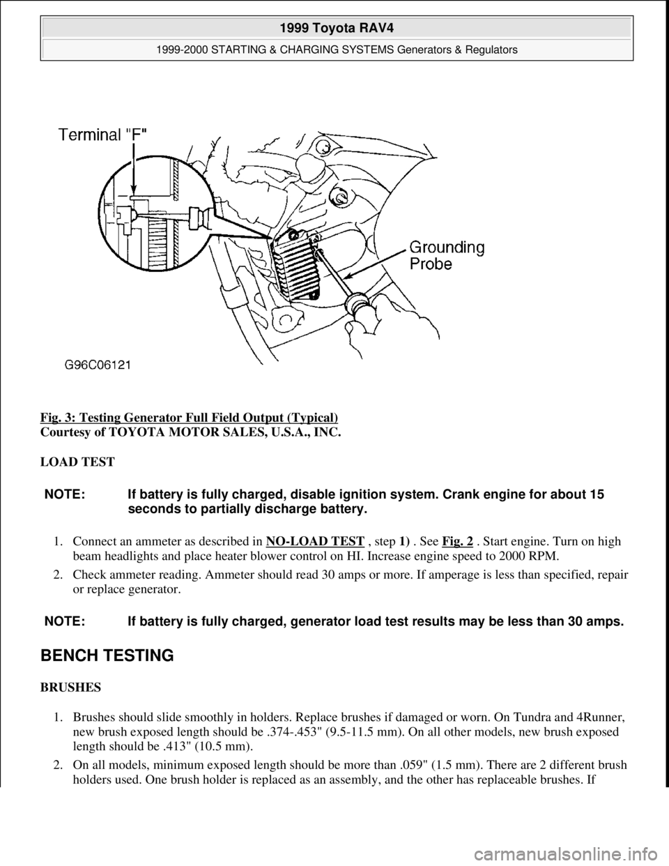
Fig. 3: Testing Generator Full Field Output (Typical)
Courtesy of TOYOTA MOTOR SALES, U.S.A., INC.
LOAD TEST
1. Connect an ammeter as described in NO
-LOAD TEST , step 1) . See Fig. 2 . Start engine. Turn on high
beam headlights and place heater blower control on HI. Increase engine speed to 2000 RPM.
2. Check ammeter reading. Ammeter should read 30 amps or more. If amperage is less than specified, repair
or replace generator.
BENCH TESTING
BRUSHES
1. Brushes should slide smoothly in holders. Replace brushes if damaged or worn. On Tundra and 4Runner,
new brush exposed length should be .374-.453" (9.5-11.5 mm). On all other models, new brush exposed
length should be .413" (10.5 mm).
2. On all models, minimum exposed length should be more than .059" (1.5 mm). There are 2 different brush
holders used. One brush holder is replaced as an assembl
y, and the other has replaceable brushes. If
NOTE: If battery is fully charged, disable ignition system. Crank engine for about 15
seconds to partially discharge battery.
NOTE: If battery is fully charged, generator load test results may be less than 30 amps.
1999 Toyota RAV4
1999-2000 STARTING & CHARGING SYSTEMS Generators & Regulators
Microsoft
Sunday, November 22, 2009 10:13:07 AMPage 6 © 2005 Mitchell Repair Information Company, LLC.
Page 557 of 1632
Courtesy of TOYOTA MOTOR SALES, U.S.A., INC.
REARVIEW MIRROR DEFOGGER TIMER OPERATION
Land Cruiser
1. Remove climate control (A/C-heater control) panel. Connect (backprobe) DVOM negative lead to
connector C9 terminal No. 22. Connect DVOM positive lead to connector C9 terminals No. 2 and 12, and
connector C7 terminal No. 8. See Fig. 12
. Turn ignition switch to ON position and measure voltage.
2. With defogger switch OFF, voltage should be about 12 volts. Turn defogger switch ON and ensure DEF
switch indicator is illuminated. Voltage should be less than one volt for about 15 minutes. After 15
minutes, defogger switch should turn off and voltage should be about 12 volts. Replace defogger switch i
f
voltage is not as specified is not as specified.
COMPONENT TESTS
DEFOGGER SWITCH TEST
1999 Avalon
1. If equipped with automatic A/C-heater system, backprobe defogger switch terminal No. 10 (Blue/Yellow
wire) with positive voltmeter lead and terminal No. 11 (White/Black wire) with negative lead. See Fig. 6
.
If equipped with manual A/C-heater system, backprobe defogger switch terminal No. 11 (Blue/Yellow
wire) with positive voltmeter lead and terminal No. 5 (White/Black wire) with negative lead. See Fig. 7
.
2. On all models, ensure battery voltage exists with defogger switch in OFF position. Turn defogger switch
to ON position. Ensure indicator light is on and less than one volt exists. After 15 minutes, defogger
switch should turn off and battery voltage should exist again. If defogger switch does not operate as
specified, replace switch.
1999 Toyota RAV4
1999-2000 ACCESSORIES & EQUIPMENT Rear Window & Mirror Defoggers
Microsoft
Sunday, November 22, 2009 10:55:10 AMPage 9 © 2005 Mitchell Repair Information Company, LLC.