relay TOYOTA RAV4 1996 Service Service Manual
[x] Cancel search | Manufacturer: TOYOTA, Model Year: 1996, Model line: RAV4, Model: TOYOTA RAV4 1996Pages: 1632, PDF Size: 41.64 MB
Page 484 of 1632
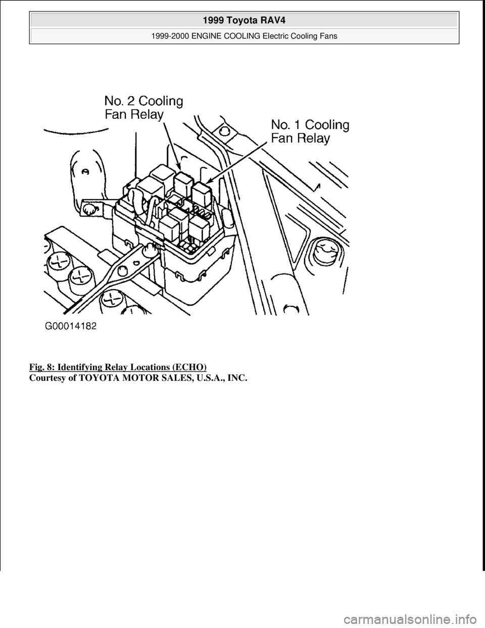
Fig. 8: Identifying Relay Locations (ECHO)
Courtesy of TOYOTA MOTOR SALES, U.S.A., INC.
1999 Toyota RAV4
1999-2000 ENGINE COOLING Electric Cooling Fans
Microsoft
Sunday, November 22, 2009 10:21:41 AMPage 14 © 2005 Mitchell Repair Information Company, LLC.
Page 485 of 1632
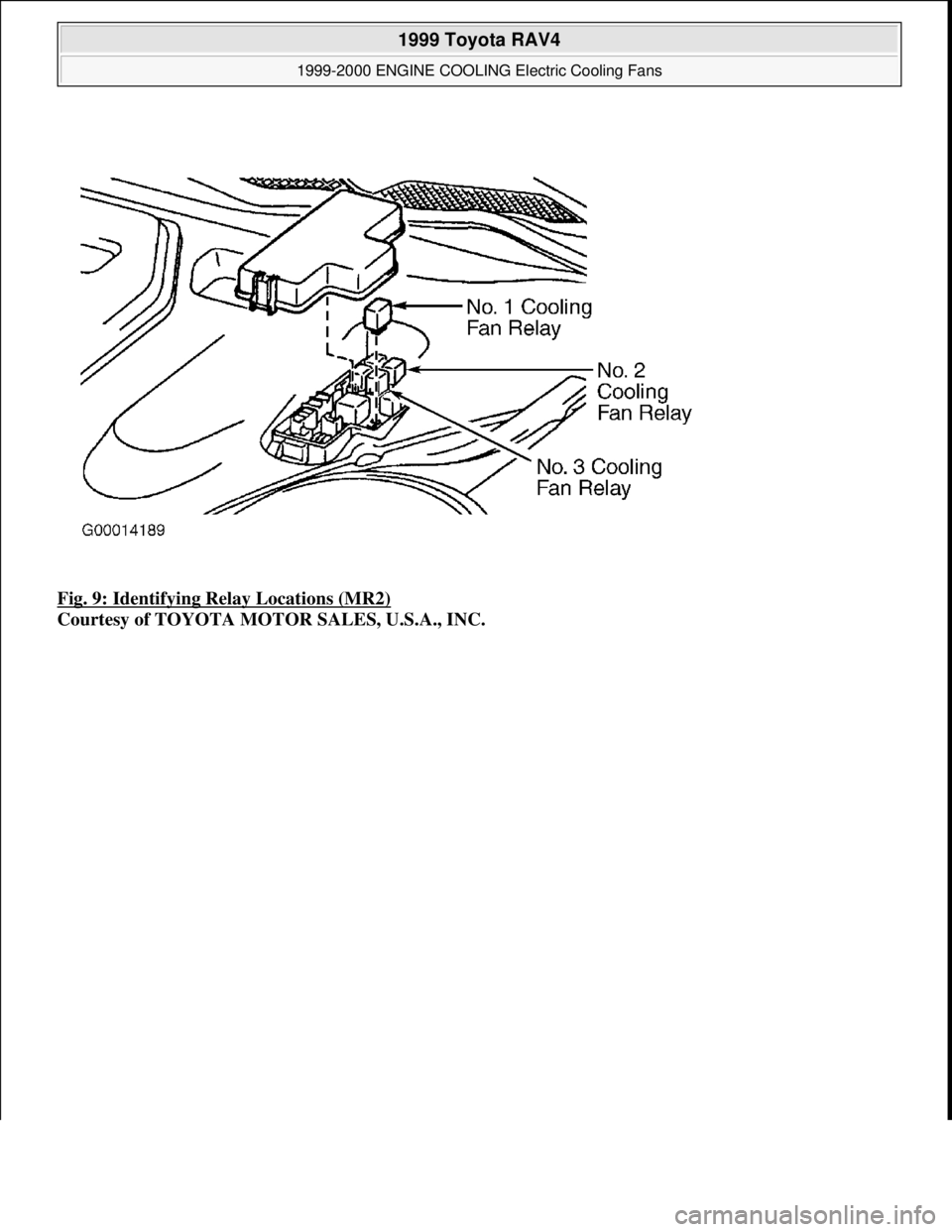
Fig. 9: Identifying Relay Locations (MR2)
Courtesy of TOYOTA MOTOR SALES, U.S.A., INC.
1999 Toyota RAV4
1999-2000 ENGINE COOLING Electric Cooling Fans
Microsoft
Sunday, November 22, 2009 10:21:41 AMPage 15 © 2005 Mitchell Repair Information Company, LLC.
Page 486 of 1632
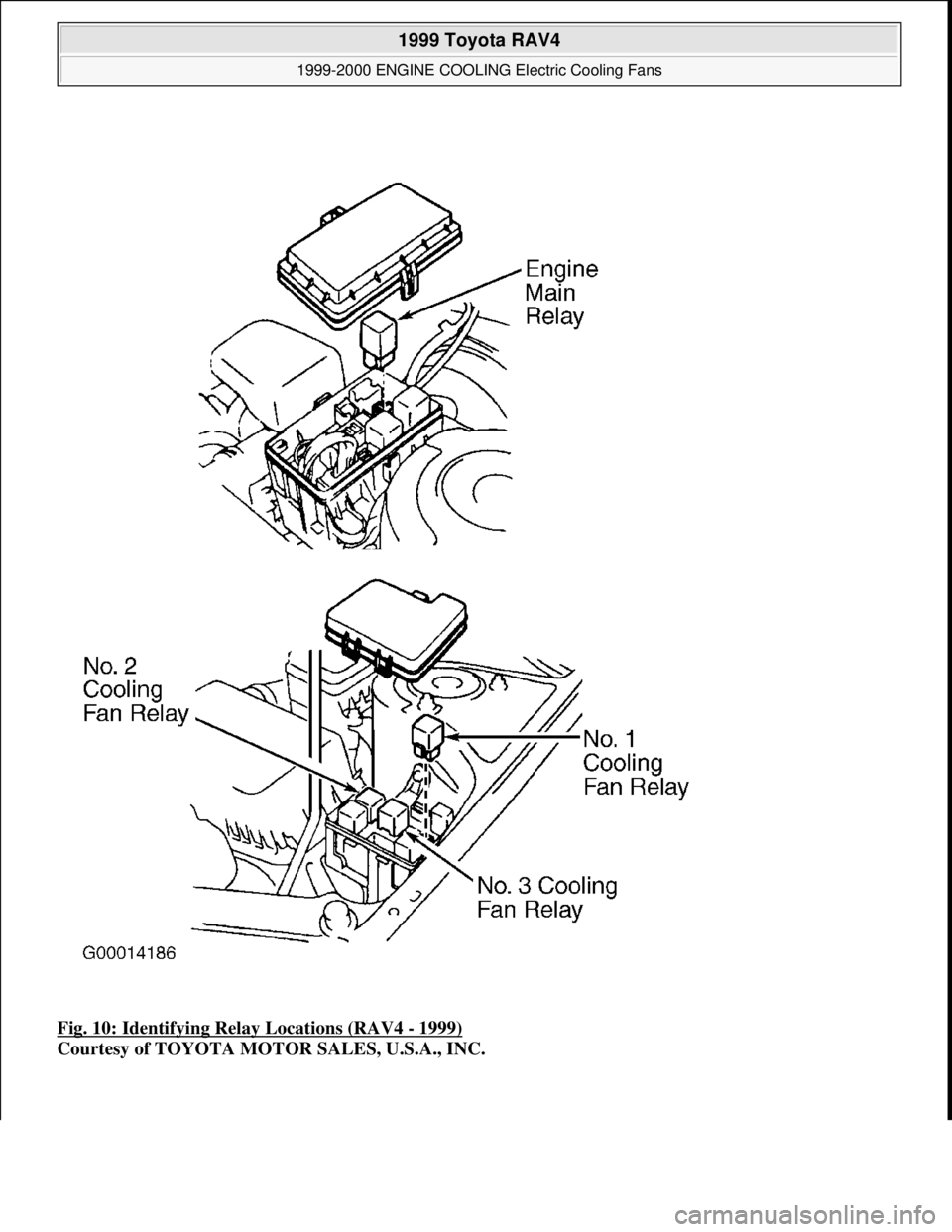
Fig. 10: Identifying Relay Locations (RAV4 - 1999)
Courtesy of TOYOTA MOTOR SALES, U.S.A., INC.
1999 Toyota RAV4
1999-2000 ENGINE COOLING Electric Cooling Fans
Microsoft
Sunday, November 22, 2009 10:21:41 AMPage 16 © 2005 Mitchell Repair Information Company, LLC.
Page 487 of 1632
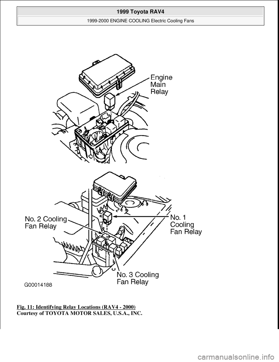
Fig. 11: Identifying Relay Locations (RAV4 - 2000)
Courtesy of TOYOTA MOTOR SALES, U.S.A., INC.
1999 Toyota RAV4
1999-2000 ENGINE COOLING Electric Cooling Fans
Microsoft
Sunday, November 22, 2009 10:21:41 AMPage 17 © 2005 Mitchell Repair Information Company, LLC.
Page 488 of 1632
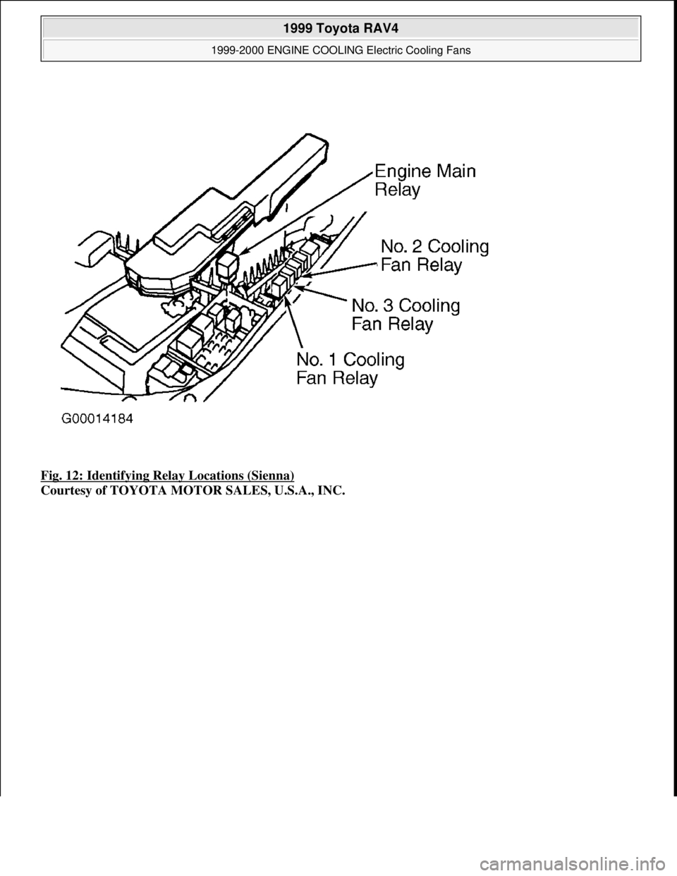
Fig. 12: Identifying Relay Locations (Sienna)
Courtesy of TOYOTA MOTOR SALES, U.S.A., INC.
1999 Toyota RAV4
1999-2000 ENGINE COOLING Electric Cooling Fans
Microsoft
Sunday, November 22, 2009 10:21:41 AMPage 18 © 2005 Mitchell Repair Information Company, LLC.
Page 490 of 1632
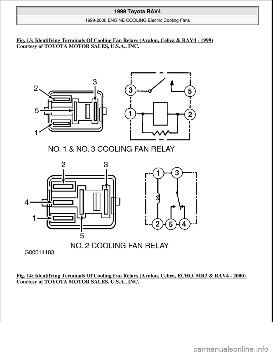
Fig. 13: Identifying Terminals Of Cooling Fan Relays (Avalon, Celica & RAV4 - 1999)
Courtesy of TOYOTA MOTOR SALES, U.S.A., INC.
Fig. 14: Identifying Terminals Of Cooling Fan Relays (Avalon, Celica, ECHO, MR2 & RAV4
- 2000)
Courtesy of TOYOTA MOTOR SALES, U.S.A., INC.
1999 Toyota RAV4
1999-2000 ENGINE COOLING Electric Cooling Fans
Microsoft
Sunday, November 22, 2009 10:21:41 AMPage 20 © 2005 Mitchell Repair Information Company, LLC.
Page 491 of 1632
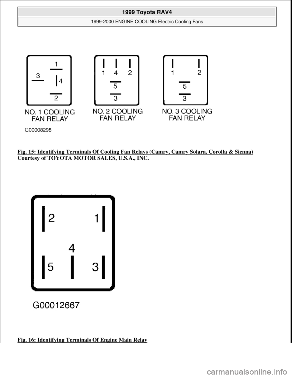
Fig. 15: Identifying Terminals Of Cooling Fan Relays (Camry, Camry Solara, Corolla & Sienna)
Courtesy of TOYOTA MOTOR SALES, U.S.A., INC.
Fig. 16: Identifying Terminals Of Engine Main Relay
1999 Toyota RAV4
1999-2000 ENGINE COOLING Electric Cooling Fans
Microsoft
Sunday, November 22, 2009 10:21:41 AMPage 21 © 2005 Mitchell Repair Information Company, LLC.
Page 549 of 1632
1999-2000 ACCESSORIES & EQUIPMENT
Rear Window & Mirror Defoggers
DESCRIPTION & OPERATION
Rear window defogger systems use a heating wire grid bonded to the inside of window. Electrical power to
heating grid is supplied by defogger relay, which is controlled by defogger switch. Some switches have an
integrated timer, which turns system off after 12-18 minutes of operation. Some models are equipped with
outside rearview mirror defoggers.
ON-VEHICLE SERVICE
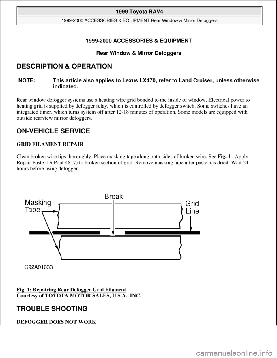
GRID FILAMENT REPAIR
Clean broken wire tips thoroughly. Place masking tape along both sides of broken wire. See Fig. 1
. Apply
Repair Paste (DuPont 4817) to broken section of grid. Remove masking tape after paste has dried. Wait 24
hours before using defogger.
Fig. 1: Repairing Rear Defogger Grid Filament
Courtesy of TOYOTA MOTOR SALES, U.S.A., INC.
TROUBLE SHOOTING
DEFOGGER DOES NOT WORK NOTE: This article also applies to Lexus LX470, refer to Land Cruiser, unless otherwise
indicated.
1999 Toyota RAV4
1999-2000 ACCESSORIES & EQUIPMENT Rear Window & Mirror Defoggers
1999 Toyota RAV4
1999-2000 ACCESSORIES & EQUIPMENT Rear Window & Mirror Defoggers
Microsoft
Sunday, November 22, 2009 10:55:09 AMPage 1 © 2005 Mitchell Repair Information Company, LLC.
Microsoft
Sunday, November 22, 2009 10:55:15 AMPage 1 © 2005 Mitchell Repair Information Company, LLC.
Page 550 of 1632
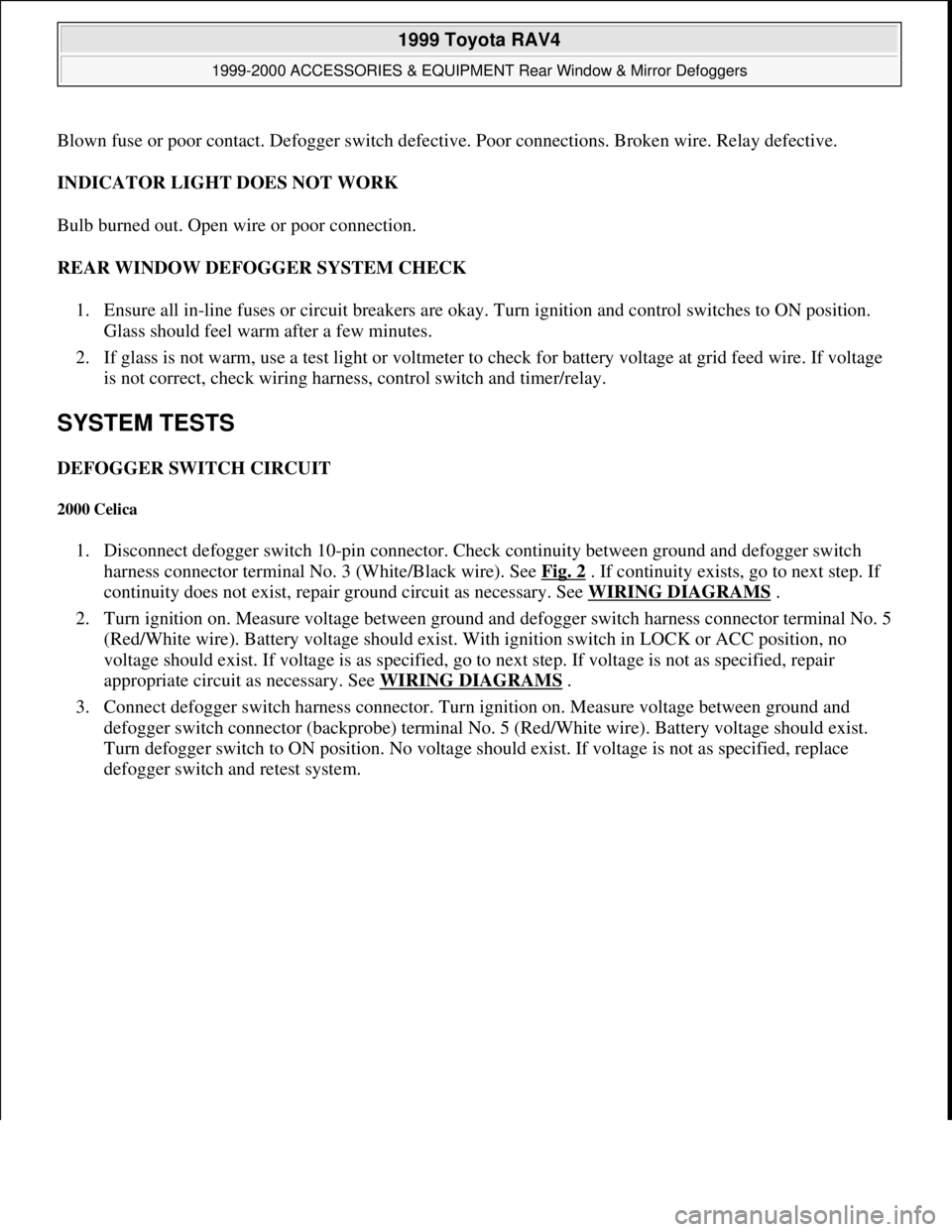
Blown fuse or poor contact. Defogger switch defective. Poor connections. Broken wire. Relay defective.
INDICATOR LIGHT DOES NOT WORK
Bulb burned out. Open wire or poor connection.
REAR WINDOW DEFOGGER SYSTEM CHECK
1. Ensure all in-line fuses or circuit breakers are okay. Turn ignition and control switches to ON position.
Glass should feel warm after a few minutes.
2. If glass is not warm, use a test light or voltmeter to check for battery voltage at grid feed wire. If voltage
is not correct, check wiring harness, control switch and timer/relay.
SYSTEM TESTS
DEFOGGER SWITCH CIRCUIT
2000 Celica
1. Disconnect defogger switch 10-pin connector. Check continuity between ground and defogger switch
harness connector terminal No. 3 (White/Black wire). See Fig. 2
. If continuity exists, go to next step. If
continuity does not exist, repair ground circuit as necessary. See WIRING DIAGRAMS
.
2. Turn ignition on. Measure voltage between ground and defogger switch harness connector terminal No. 5
(Red/White wire). Battery voltage should exist. With ignition switch in LOCK or ACC position, no
voltage should exist. If voltage is as specified, go to next step. If voltage is not as specified, repair
appropriate circuit as necessary. See WIRING DIAGRAMS
.
3. Connect defogger switch harness connector. Turn ignition on. Measure voltage between ground and
defogger switch connector (backprobe) terminal No. 5 (Red/White wire). Battery voltage should exist.
Turn defogger switch to ON position. No voltage should exist. If voltage is not as specified, replace
defo
gger switch and retest system.
1999 Toyota RAV4
1999-2000 ACCESSORIES & EQUIPMENT Rear Window & Mirror Defoggers
Microsoft
Sunday, November 22, 2009 10:55:10 AMPage 2 © 2005 Mitchell Repair Information Company, LLC.
Page 555 of 1632
4Runner
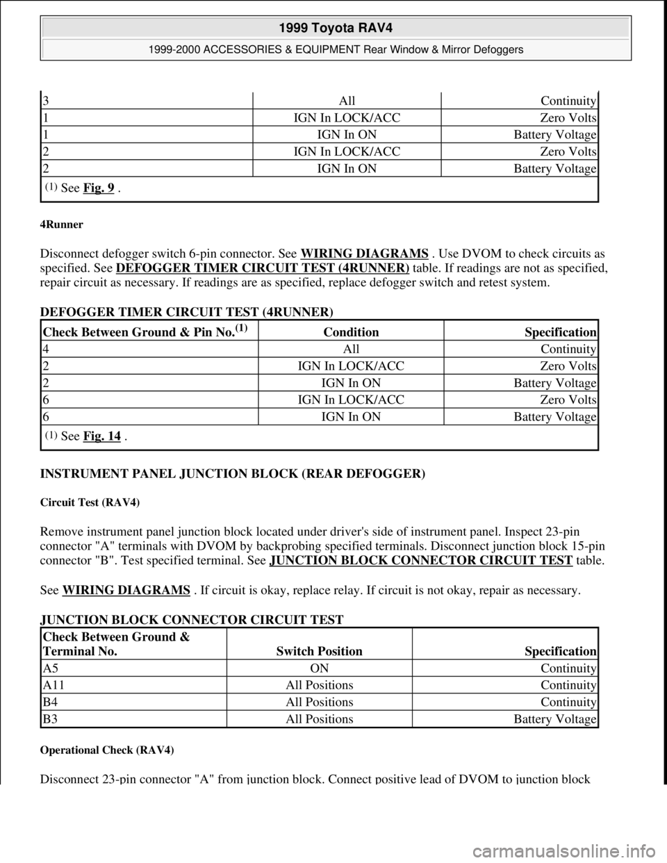
Disconnect defogger switch 6-pin connector. See WIRING DIAGRAMS . Use DVOM to check circuits as
specified. See DEFOGGER TIMER CIRCUIT TEST (4RUNNER)
table. If readings are not as specified,
repair circuit as necessary. If readings are as specified, replace defogger switch and retest system.
DEFOGGER TIMER CIRCUIT TEST (4RUNNER)
INSTRUMENT PANEL JUNCTION BLOCK (REAR DEFOGGER)
Circuit Test (RAV4)
Remove instrument panel junction block located under driver's side of instrument panel. Inspect 23-pin
connector "A" terminals with DVOM by backprobing specified terminals. Disconnect junction block 15-pin
connector "B". Test specified terminal. See JUNCTION BLOCK CONNECTOR CIRCUIT TEST
table.
See WIRING DIAGRAMS
. If circuit is okay, replace relay. If circuit is not okay, repair as necessary.
JUNCTION BLOCK CONNECTOR CIRCUIT TEST
Operational Check (RAV4)
Disconnect 23-pin connector "A" from junction block. Connect positive lead of DVOM to junction block
3AllContinuity
1IGN In LOCK/ACCZero Volts
1IGN In ONBattery Voltage
2IGN In LOCK/ACCZero Volts
2IGN In ONBattery Voltage
(1)See Fig. 9 .
Check Between Ground & Pin No.(1) ConditionSpecification
4AllContinuity
2IGN In LOCK/ACCZero Volts
2IGN In ONBattery Voltage
6IGN In LOCK/ACCZero Volts
6IGN In ONBattery Voltage
(1)See Fig. 14 .
Check Between Ground &
Terminal No.
Switch PositionSpecification
A5ONContinuity
A11All PositionsContinuity
B4All PositionsContinuity
B3All PositionsBattery Voltage
1999 Toyota RAV4
1999-2000 ACCESSORIES & EQUIPMENT Rear Window & Mirror Defoggers
Microsoft
Sunday, November 22, 2009 10:55:10 AMPage 7 © 2005 Mitchell Repair Information Company, LLC.