door TOYOTA RAV4 1996 Service Repair Manual
[x] Cancel search | Manufacturer: TOYOTA, Model Year: 1996, Model line: RAV4, Model: TOYOTA RAV4 1996Pages: 1632, PDF Size: 41.64 MB
Page 4 of 1632
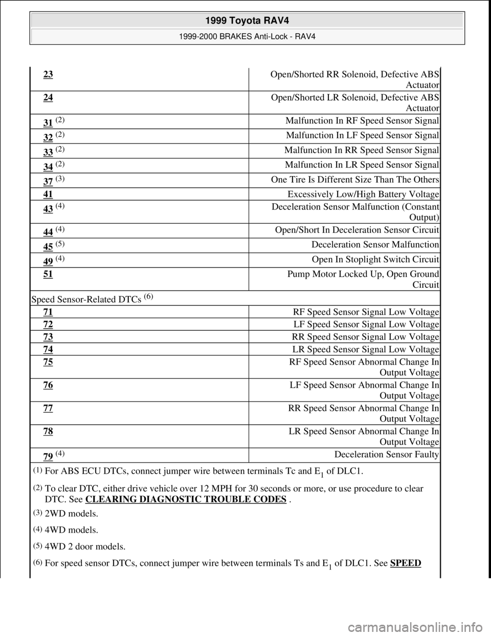
23 Open/Shorted RR Solenoid, Defective ABS
Actuator
24 Open/Shorted LR Solenoid, Defective ABS
Actuator
31 (2) Malfunction In RF Speed Sensor Signal
32 (2) Malfunction In LF Speed Sensor Signal
33 (2) Malfunction In RR Speed Sensor Signal
34 (2) Malfunction In LR Speed Sensor Signal
37 (3) One Tire Is Different Size Than The Others
41 Excessively Low/High Battery Voltage
43 (4) Deceleration Sensor Malfunction (Constant
Output)
44 (4) Open/Short In Deceleration Sensor Circuit
45 (5) Deceleration Sensor Malfunction
49 (4) Open In Stoplight Switch Circuit
51 Pump Motor Locked Up, Open Ground
Circuit
Speed Sensor-Related DTCs (6)
71 RF Speed Sensor Signal Low Voltage
72 LF Speed Sensor Signal Low Voltage
73 RR Speed Sensor Signal Low Voltage
74 LR Speed Sensor Signal Low Voltage
75 RF Speed Sensor Abnormal Change In
Output Voltage
76 LF Speed Sensor Abnormal Change In
Output Voltage
77 RR Speed Sensor Abnormal Change In
Output Voltage
78 LR Speed Sensor Abnormal Change In
Output Voltage
79 (4) Deceleration Sensor Faulty
(1)For ABS ECU DTCs, connect jumper wire between terminals Tc and E1 of DLC1.
(2)To clear DTC, either drive vehicle over 12 MPH for 30 seconds or more, or use procedure to clear
DTC. See CLEARING DIAGNOSTIC TROUBLE CODES
.
(3)2WD models.
(4)4WD models.
(5)4WD 2 door models.
(6)For speed sensor DTCs, connect jumper wire between terminals Ts and E1 of DLC1. See SPEED
1999 Toyota RAV4
1999-2000 BRAKES Anti-Lock - RAV4
Microsoft
Sunday, November 22, 2009 10:06:17 AMPage 4 © 2005 Mitchell Repair Information Company, LLC.
Page 17 of 1632
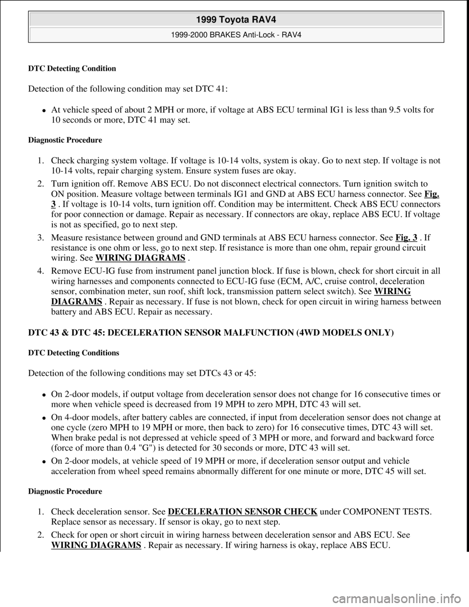
DTC Detecting Condition
Detection of the following condition may set DTC 41:
At vehicle speed of about 2 MPH or more, if voltage at ABS ECU terminal IG1 is less than 9.5 volts for
10 seconds or more, DTC 41 may set.
Diagnostic Procedure
1. Check charging system voltage. If voltage is 10-14 volts, system is okay. Go to next step. If voltage is not
10-14 volts, repair charging system. Ensure system fuses are okay.
2. Turn ignition off. Remove ABS ECU. Do not disconnect electrical connectors. Turn ignition switch to
ON position. Measure voltage between terminals IG1 and GND at ABS ECU harness connector. See Fig.
3 . If voltage is 10-14 volts, turn ignition off. Condition may be intermittent. Check ABS ECU connectors
for poor connection or damage. Repair as necessary. If connectors are okay, replace ABS ECU. If voltage
is not as specified, go to next step.
3. Measure resistance between ground and GND terminals at ABS ECU harness connector. See Fig. 3
. If
resistance is one ohm or less, go to next step. If resistance is more than one ohm, repair ground circuit
wiring. See WIRING DIAGRAMS
.
4. Remove ECU-IG fuse from instrument panel junction block. If fuse is blown, check for short circuit in all
wiring harnesses and components connected to ECU-IG fuse (ECM, A/C, cruise control, deceleration
sensor, combination meter, sun roof, shift lock, transmission pattern select switch). See WIRING
DIAGRAMS . Repair as necessary. If fuse is not blown, check for open circuit in wiring harness between
battery and ABS ECU. Repair as necessary.
DTC 43 & DTC 45: DECELERATION SENSOR MALFUNCTION (4WD MODELS ONLY)
DTC Detecting Conditions
Detection of the following conditions may set DTCs 43 or 45:
On 2-door models, if output voltage from deceleration sensor does not change for 16 consecutive times or
more when vehicle speed is decreased from 19 MPH to zero MPH, DTC 43 will set.
On 4-door models, after battery cables are connected, if input from deceleration sensor does not change at
one cycle (zero MPH to 19 MPH or more, then back to zero) for 16 consecutive times, DTC 43 will set.
When brake pedal is not depressed at vehicle speed of 3 MPH or more, and forward and backward force
(force of more than 0.4 "G") is detected for 30 seconds or more, DTC 43 will set.
On 2-door models, at vehicle speed of 19 MPH or more, if deceleration sensor output and vehicle
acceleration from wheel speed remains abnormally different for one minute or more, DTC 45 will set.
Diagnostic Procedure
1. Check deceleration sensor. See DECELERATION SENSOR CHECK under COMPONENT TESTS.
Replace sensor as necessary. If sensor is okay, go to next step.
2. Check for open or short circuit in wiring harness between deceleration sensor and ABS ECU. See
WIRING DIAGRAMS
. Repair as necessary. If wiring harness is okay, replace ABS ECU.
1999 Toyota RAV4
1999-2000 BRAKES Anti-Lock - RAV4
Microsoft
Sunday, November 22, 2009 10:06:17 AMPage 17 © 2005 Mitchell Repair Information Company, LLC.
Page 18 of 1632
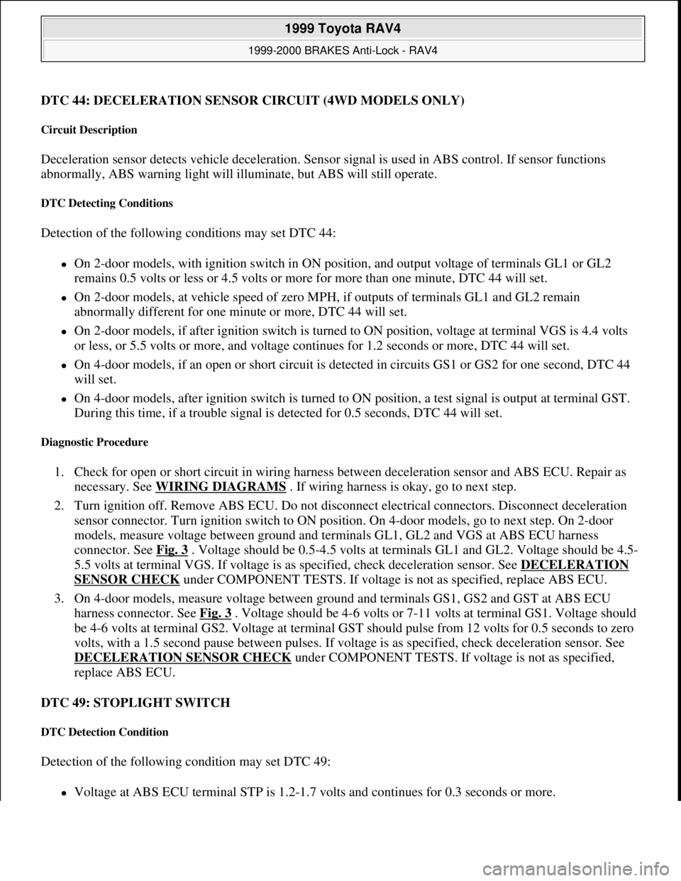
DTC 44: DECELERATION SENSOR CIRCUIT (4WD MODELS ONLY)
Circuit Description
Deceleration sensor detects vehicle deceleration. Sensor signal is used in ABS control. If sensor functions
abnormally, ABS warning light will illuminate, but ABS will still operate.
DTC Detecting Conditions
Detection of the following conditions may set DTC 44:
On 2-door models, with ignition switch in ON position, and output voltage of terminals GL1 or GL2
remains 0.5 volts or less or 4.5 volts or more for more than one minute, DTC 44 will set.
On 2-door models, at vehicle speed of zero MPH, if outputs of terminals GL1 and GL2 remain
abnormally different for one minute or more, DTC 44 will set.
On 2-door models, if after ignition switch is turned to ON position, voltage at terminal VGS is 4.4 volts
or less, or 5.5 volts or more, and voltage continues for 1.2 seconds or more, DTC 44 will set.
On 4-door models, if an open or short circuit is detected in circuits GS1 or GS2 for one second, DTC 44
will set.
On 4-door models, after ignition switch is turned to ON position, a test signal is output at terminal GST.
During this time, if a trouble signal is detected for 0.5 seconds, DTC 44 will set.
Diagnostic Procedure
1. Check for open or short circuit in wiring harness between deceleration sensor and ABS ECU. Repair as
necessary. See WIRING DIAGRAMS
. If wiring harness is okay, go to next step.
2. Turn ignition off. Remove ABS ECU. Do not disconnect electrical connectors. Disconnect deceleration
sensor connector. Turn ignition switch to ON position. On 4-door models, go to next step. On 2-door
models, measure voltage between ground and terminals GL1, GL2 and VGS at ABS ECU harness
connector. See Fig. 3
. Voltage should be 0.5-4.5 volts at terminals GL1 and GL2. Voltage should be 4.5-
5.5 volts at terminal VGS. If voltage is as specified, check deceleration sensor. See DECELERATION
SENSOR CHECK under COMPONENT TESTS. If voltage is not as specified, replace ABS ECU.
3. On 4-door models, measure voltage between ground and terminals GS1, GS2 and GST at ABS ECU
harness connector. See Fig. 3
. Voltage should be 4-6 volts or 7-11 volts at terminal GS1. Voltage should
be 4-6 volts at terminal GS2. Voltage at terminal GST should pulse from 12 volts for 0.5 seconds to zero
volts, with a 1.5 second pause between pulses. If voltage is as specified, check deceleration sensor. See
DECELERATION SENSOR CHECK
under COMPONENT TESTS. If voltage is not as specified,
replace ABS ECU.
DTC 49: STOPLIGHT SWITCH
DTC Detection Condition
Detection of the following condition may set DTC 49:
Voltage at ABS ECU terminal STP is 1.2-1.7 volts and continues for 0.3 seconds or more.
1999 Toyota RAV4
1999-2000 BRAKES Anti-Lock - RAV4
Microsoft
Sunday, November 22, 2009 10:06:17 AMPage 18 © 2005 Mitchell Repair Information Company, LLC.
Page 24 of 1632
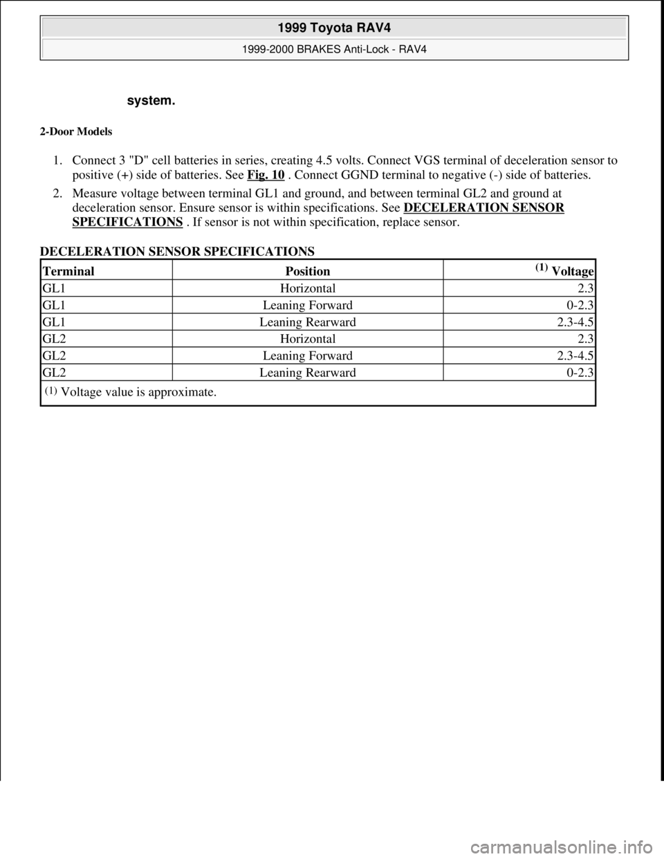
2-Door Models
1. Connect 3 "D" cell batteries in series, creating 4.5 volts. Connect VGS terminal of deceleration sensor to
positive (+) side of batteries. See Fig. 10
. Connect GGND terminal to negative (-) side of batteries.
2. Measure voltage between terminal GL1 and ground, and between terminal GL2 and ground at
deceleration sensor. Ensure sensor is within specifications. See DECELERATION SENSOR
SPECIFICATIONS . If sensor is not within specification, replace sensor.
DECELERATION SENSOR SPECIFICATIONS system.
TerminalPosition(1) Voltage
GL1Horizontal2.3
GL1Leaning Forward0-2.3
GL1Leaning Rearward2.3-4.5
GL2Horizontal2.3
GL2Leaning Forward2.3-4.5
GL2Leaning Rearward0-2.3
(1)Voltage value is approximate.
1999 Toyota RAV4
1999-2000 BRAKES Anti-Lock - RAV4
Microsoft
Sunday, November 22, 2009 10:06:17 AMPage 24 © 2005 Mitchell Repair Information Company, LLC.
Page 25 of 1632
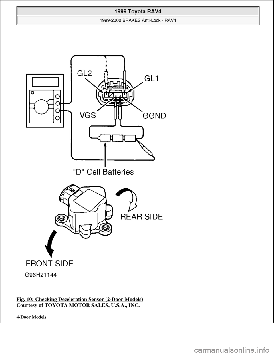
Fig. 10: Checking Deceleration Sensor (2-Door Models)
Courtesy of TOYOTA MOTOR SALES, U.S.A., INC.
4-Door Models
1999 Toyota RAV4
1999-2000 BRAKES Anti-Lock - RAV4
Microsoft
Sunday, November 22, 2009 10:06:17 AMPage 25 © 2005 Mitchell Repair Information Company, LLC.
Page 38 of 1632
disable system from operating normally. If SRS is not functional, park vehicle until it is repaired and
functions properly.
DISABLING & ACTIVATING AIR BAG SYSTEM
DISABLING SYSTEM
Turn ignition switch to LOCK position. Disconnect and shield negative battery cable. Wait at least 90 seconds
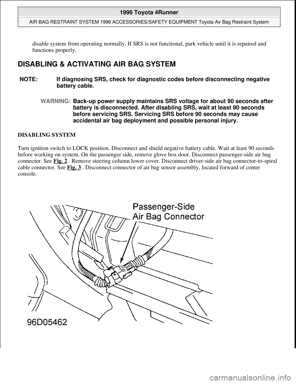
before working on system. On the passenger side, remove glove box door. Disconnect passenger-side air bag
connector. See Fig. 2
. Remove steering column lower cover. Disconnect driver-side air bag connector-to-spiral
cable connector. See Fig. 3
. Disconnect connector of air bag sensor assembly, located forward of center
console. NOTE: If diagnosing SRS, check for diagnostic codes before disconnecting negative
battery cable.
WARNING:Back-up power supply maintains SRS voltage for about 90 seconds after
battery is disconnected. After disabling SRS, wait at least 90 seconds
before servicing SRS. Servicing SRS before 90 seconds may cause
accidental air bag deployment and possible personal injury.
1996 Toyota 4Runner
AIR BAG RESTRAINT SYSTEM 1996 ACCESSORIES/SAFETY EQUIPMENT Toyota Air Bag Restraint System
Microsoft
Tuesday, August 18, 2009 7:33:32 PMPage 4 © 2005 Mitchell Repair Information Company, LLC.
Page 40 of 1632
DEPLOYING AIR BAG
On-Vehicle Deployment (Scrapped Vehicles Only)
1. Before proceeding, follow service precautions. See SERVICE PRECAUTIONS . Turn ignition switch
to LOCK position. Disconnect and shield negative battery cable. Wait at least 90 seconds before working
on system.
2. Disable air bag system. See DISABLING & ACTIVATING AIR BAG SYSTEM
. Connect
Deployment Tool (09082-00700) to air bag connector. Position deployment tool at least 33 feet from
front of vehicle.
3. Close all doors and windows of vehicle. Connect deployment tool Red clip to positive battery terminal
and Black clip to negative battery terminal. Ensure no one is within 33 feet of vehicle. Press deployment
tool activation switch to deploy air bag. Because of heat, DO NOT touch air bag for at least 30 minutes
after deployment.
Off-Vehicle Deployment (Driver-Side)
1. Before proceeding, see SERVICE PRECAUTIONS . Disable SRS. See DISABLING &
ACTIVATING AIR BAG SYSTEM . Remove steering wheel pad from vehicle. See STEERING
WHEEL PAD & SPIRAL CABLE under REMOVAL & INSTALLATION.
2. Remove connector on steering wheel pad rear surface and install 2.236" (6.0 mm) bolts (1.38" 35 mm
long) with washers in steering wheel pad. Bolts should have a pitch of .039" (1.0 mm). Tighten bolts by
hand until they become difficult to turn. DO NOT overtighten bolts. Obtain a wheel and tire assembly.
Using a service-purpose wire harness, tie down the steering wheel pad to the wheel and tire assembly.
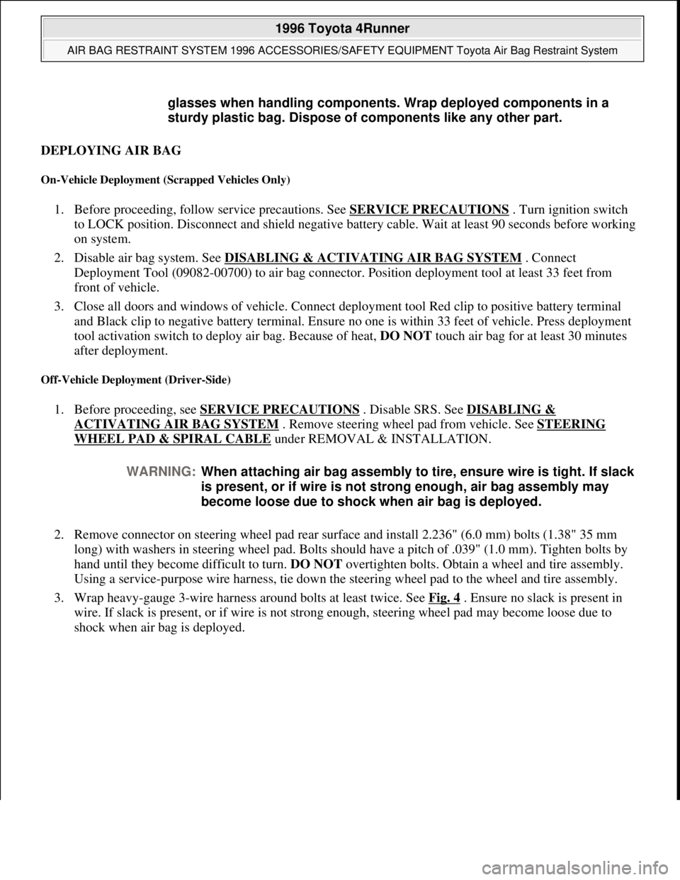
3. Wrap heavy-gauge 3-wire harness around bolts at least twice. See Fig. 4
. Ensure no slack is present in
wire. If slack is present, or if wire is not strong enough, steering wheel pad may become loose due to
shock when air ba
g is deployed. glasses when handling components. Wrap deployed components in a
sturdy plastic bag. Dispose of components like any other part.
WARNING:When attaching air bag assembly to tire, ensure wire is tight. If slack
is present, or if wire is not strong enough, air bag assembly may
become loose due to shock when air bag is deployed.
1996 Toyota 4Runner
AIR BAG RESTRAINT SYSTEM 1996 ACCESSORIES/SAFETY EQUIPMENT Toyota Air Bag Restraint System
Microsoft
Tuesday, August 18, 2009 7:33:32 PMPage 6 © 2005 Mitchell Repair Information Company, LLC.
Page 47 of 1632
Installation
To install, reverse removal procedure. Ensure spiral cable is properly aligned. See SPIRAL CABLE under
ADJUSTMENTS. Connect air bag connector. Tighten 2 Torx screws to specification. See TORQUE
SPECIFICATIONS . Install steering wheel side covers. Perform SYSTEM OPERATION CHECK .
PASSENGER-SIDE AIR BAG
Removal & Installation
1. Before proceeding, follow air bag service precautions. See SERVICE PRECAUTIONS . Turn ignition
switch to LOCK position. Disconnect and shield negative battery cable. Wait at least 90 seconds before
working on system.
2. Disable SRS. See DISABLING & ACTIVATING AIR BAG SYSTEM
. Remove instrument panel.
Remove the 2 bolts securing passenger-side air bag. See Fig. 10
. Remove air bag. Remove 3 bolts and
pry up the 5 air bag door clips and remove the air bag door. See Fig. 11
.
3. To install, reverse removal procedure. Tighten passenger-side air bag bolts to specification. See
TORQUE SPECIFICATIONS
. Activate SRS. See DISABLING & ACTIVATING AIR BAG
SYSTEM . Check air bag warning light to ensure system is functioning properly. See SYSTEM
OPERATION CHECK . WARNING:During installation, if spiral cable mating mark is not properly aligned,
steering wheel may not turn completely, or flat cable inside spiral cable
may be severed, disabling SRS system.
1996 Toyota 4Runner
AIR BAG RESTRAINT SYSTEM 1996 ACCESSORIES/SAFETY EQUIPMENT Toyota Air Bag Restraint System
Microsoft
Tuesday, August 18, 2009 7:33:32 PMPage 13 © 2005 Mitchell Repair Information Company, LLC.
Page 49 of 1632
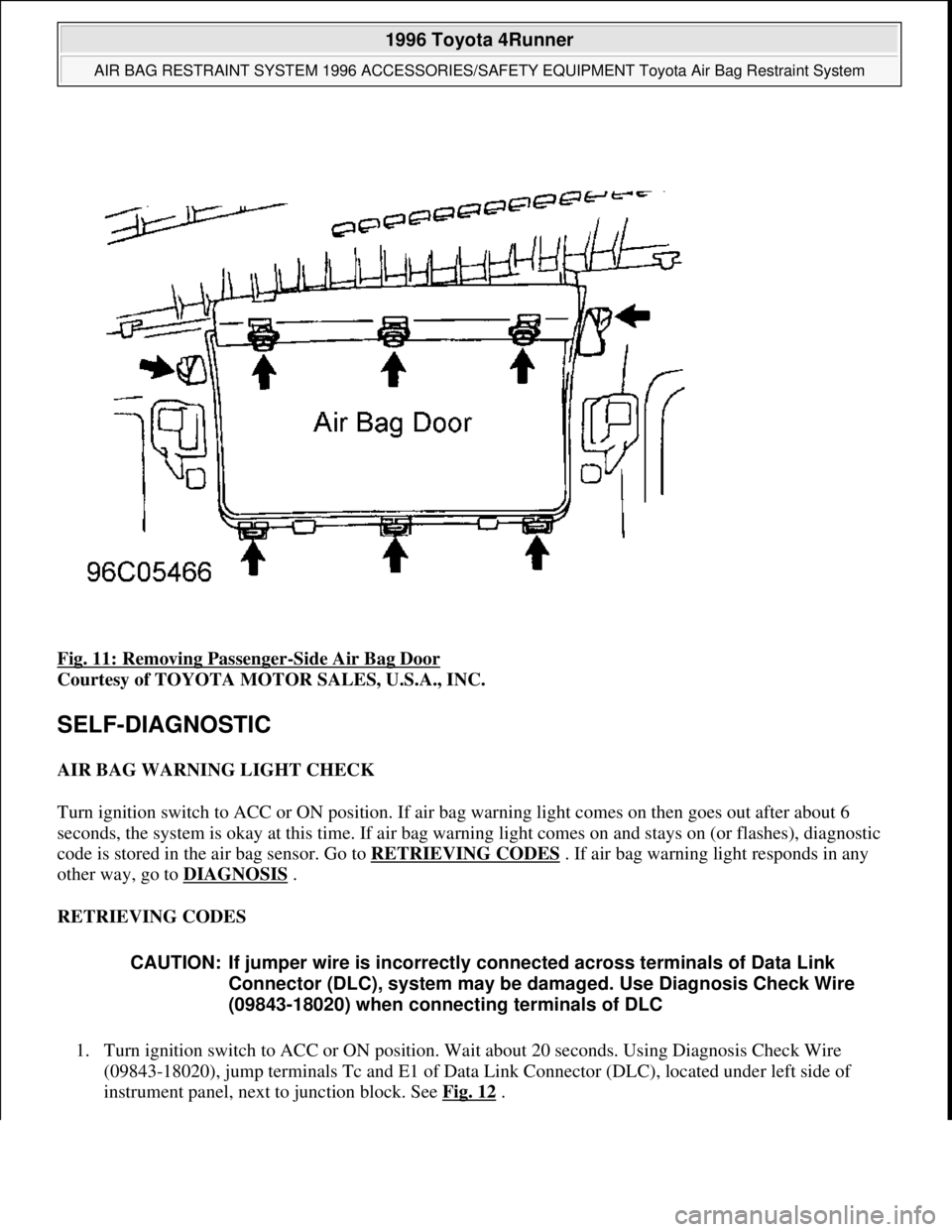
Fig. 11: Removing Passenger-Side Air Bag Door
Courtesy of TOYOTA MOTOR SALES, U.S.A., INC.
SELF-DIAGNOSTIC
AIR BAG WARNING LIGHT CHECK
Turn ignition switch to ACC or ON position. If air bag warning light comes on then goes out after about 6
seconds, the system is okay at this time. If air bag warning light comes on and stays on (or flashes), diagnostic
code is stored in the air bag sensor. Go to RETRIEVING CODES
. If air bag warning light responds in any
other way, go to DIAGNOSIS
.
RETRIEVING CODES
1. Turn ignition switch to ACC or ON position. Wait about 20 seconds. Using Diagnosis Check Wire
(09843-18020), jump terminals Tc and E1 of Data Link Connector (DLC), located under left side of
instrument panel, next to junction block. See Fig. 12
.
CAUTION: If jumper wire is incorrectly connected across terminals of Data Link
Connector (DLC), system may be damaged. Use Diagnosis Check Wire
(09843-18020) when connecting terminals of DLC
1996 Toyota 4Runner
AIR BAG RESTRAINT SYSTEM 1996 ACCESSORIES/SAFETY EQUIPMENT Toyota Air Bag Restraint System
Microsoft
Tuesday, August 18, 2009 7:33:32 PMPage 15 © 2005 Mitchell Repair Information Company, LLC.
Page 60 of 1632
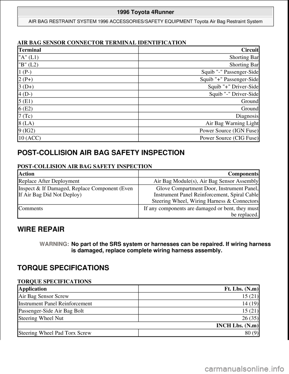
AIR BAG SENSOR CONNECTOR TERMINAL IDENTIFICATION
POST-COLLISION AIR BAG SAFETY INSPECTION
POST-COLLISION AIR BAG SAFETY INSPECTION
WIRE REPAIR
TORQUE SPECIFICATIONS
TORQUE SPECIFICATIONS
TerminalCircuit
"A" (L1)Shorting Bar
"B" (L2)Shorting Bar
1 (P-)Squib "-" Passenger-Side
2 (P+)Squib "+" Passenger-Side
3 (D+)Squib "+" Driver-Side
4 (D-)Squib "-" Driver-Side
5 (E1)Ground
6 (E2)Ground
7 (Tc)Diagnosis
8 (LA)Air Bag Warning Light
9 (IG2)Power Source (IGN Fuse)
10 (ACC)Power Source (CIG Fuse)
ActionComponents
Replace After DeploymentAir Bag Module(s), Air Bag Sensor Assembly
Inspect & If Damaged, Replace Component (Even
If Air Bag Did Not Deploy)Glove Compartment Door, Instrument Panel,
Instrument Panel Reinforcement, Spiral Cable
Steering Wheel, Wiring Harness & Connectors
CommentsIf any components are damaged or bent, they must
be replaced.
WARNING:No part of the SRS system or harnesses can be repaired. If wiring harness
is damaged, replace complete wiring harness assembly.
ApplicationFt. Lbs. (N.m)
Air Bag Sensor Screw15 (21)
Instrument Panel Reinforcement14 (19)
Passenger-Side Air Bag Bolt15 (21)
Steering Wheel Nut26 (35)
INCH Lbs. (N.m)
Steering Wheel Pad Torx Screw80 (9)
1996 Toyota 4Runner
AIR BAG RESTRAINT SYSTEM 1996 ACCESSORIES/SAFETY EQUIPMENT Toyota Air Bag Restraint System
Microsoft
Tuesday, August 18, 2009 7:33:32 PMPage 26 © 2005 Mitchell Repair Information Company, LLC.