oil change TOYOTA RAV4 1996 Service Repair Manual
[x] Cancel search | Manufacturer: TOYOTA, Model Year: 1996, Model line: RAV4, Model: TOYOTA RAV4 1996Pages: 1632, PDF Size: 41.64 MB
Page 15 of 1632
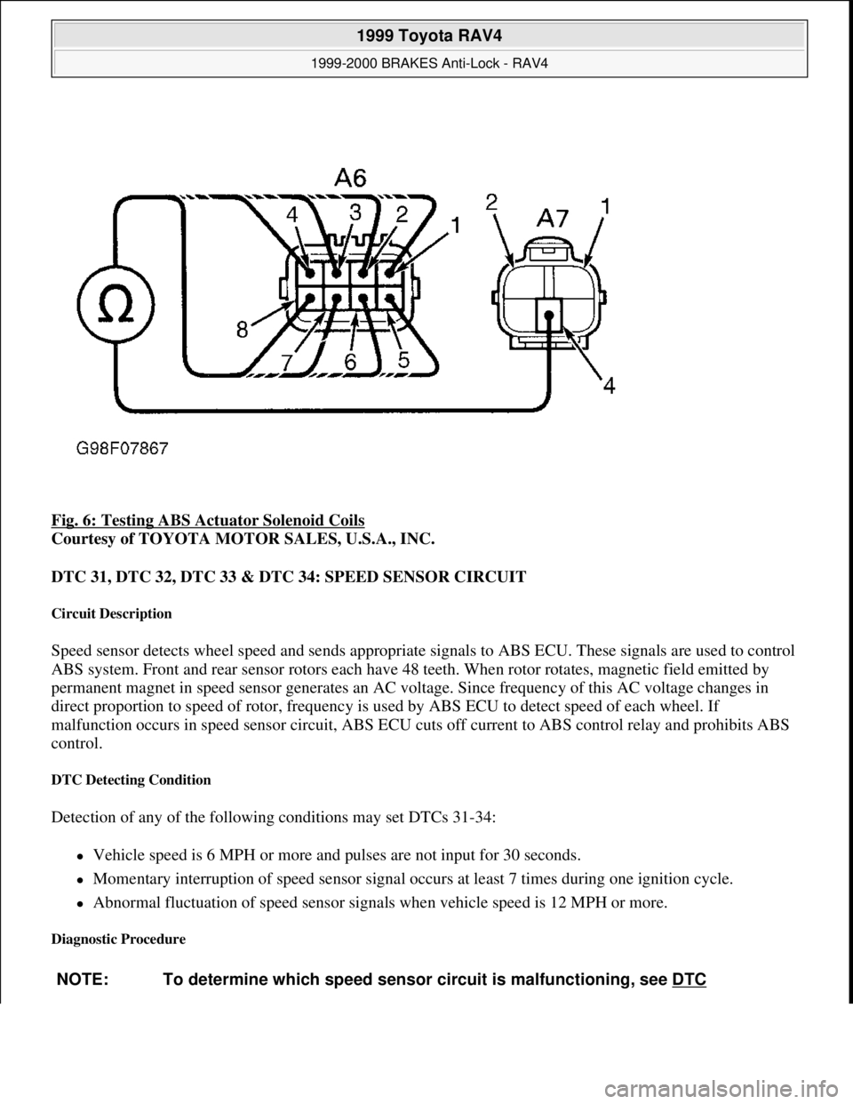
Fig. 6: Testing ABS Actuator Solenoid Coils
Courtesy of TOYOTA MOTOR SALES, U.S.A., INC.
DTC 31, DTC 32, DTC 33 & DTC 34: SPEED SENSOR CIRCUIT
Circuit Description
Speed sensor detects wheel speed and sends appropriate signals to ABS ECU. These signals are used to control
ABS system. Front and rear sensor rotors each have 48 teeth. When rotor rotates, magnetic field emitted by
permanent magnet in speed sensor generates an AC voltage. Since frequency of this AC voltage changes in
direct proportion to speed of rotor, frequency is used by ABS ECU to detect speed of each wheel. If
malfunction occurs in speed sensor circuit, ABS ECU cuts off current to ABS control relay and prohibits ABS
control.
DTC Detecting Condition
Detection of any of the following conditions may set DTCs 31-34:
Vehicle speed is 6 MPH or more and pulses are not input for 30 seconds.
Momentary interruption of speed sensor signal occurs at least 7 times during one ignition cycle.
Abnormal fluctuation of speed sensor signals when vehicle speed is 12 MPH or more.
Diagnostic Procedure
NOTE: To determine which speed sensor circuit is malfunctioning, see DTC
1999 Toyota RAV4
1999-2000 BRAKES Anti-Lock - RAV4
Microsoft
Sunday, November 22, 2009 10:06:17 AMPage 15 © 2005 Mitchell Repair Information Company, LLC.
Page 198 of 1632
select a new piston rod. Piston stroke should be .079-.138" (2.00-3.50 mm). Piston rod is available in lengths of
3.748" (95.20 mm) and 3.791" (96.30 mm).
Reassembly
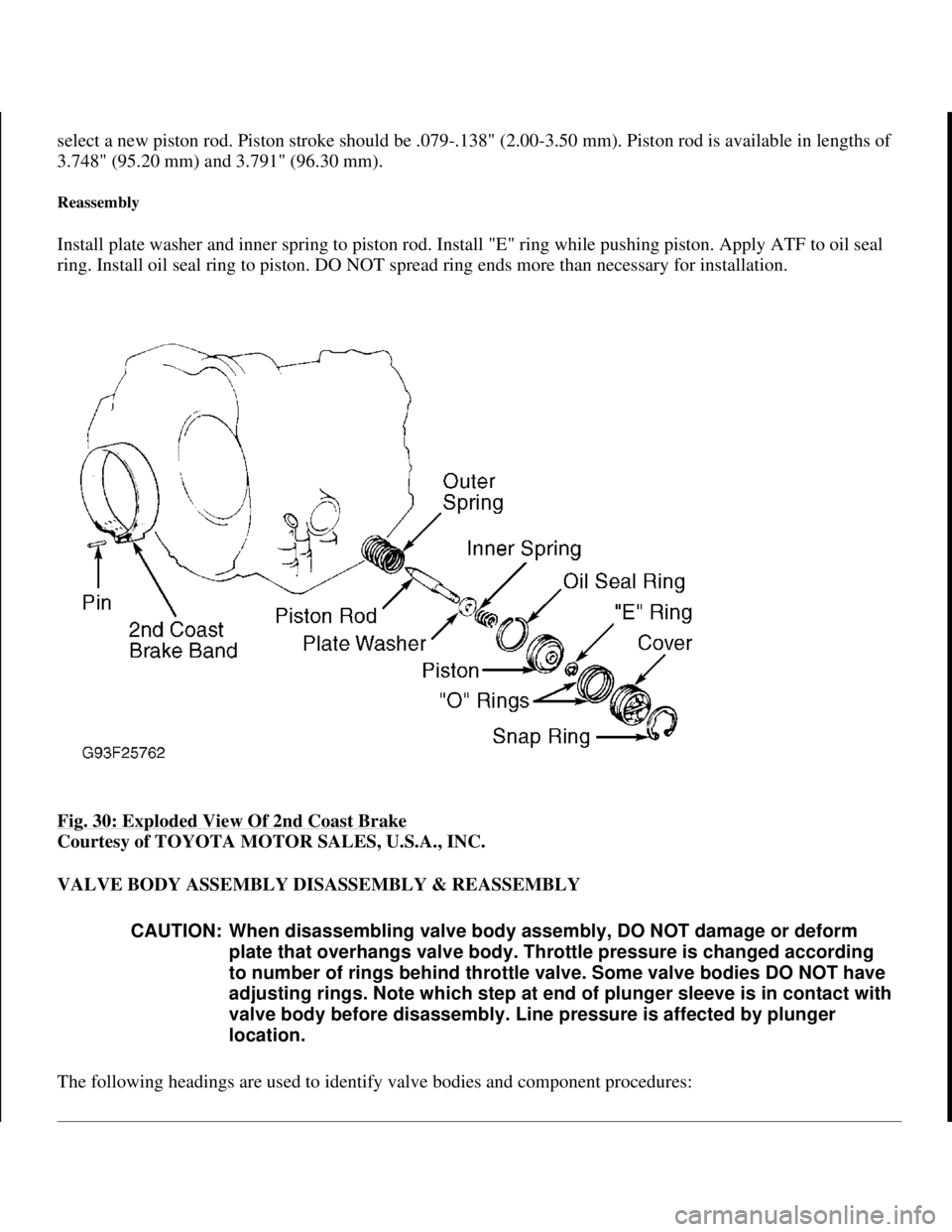
Install plate washer and inner spring to piston rod. Install "E" ring while pushing piston. Apply ATF to oil seal
ring. Install oil seal ring to piston. DO NOT spread ring ends more than necessary for installation.
Fig. 30: Exploded View Of 2nd Coast Brake
Courtesy of TOYOTA MOTOR SALES, U.S.A., INC.
VALVE BODY ASSEMBLY DISASSEMBLY & REASSEMBLY
The followin
g headings are used to identify valve bodies and component procedures:
CAUTION: When disassembling valve body assembly, DO NOT damage or deform
plate that overhangs valve body. Throttle pressure is changed according
to number of rings behind throttle valve. Some valve bodies DO NOT have
adjusting rings. Note which step at end of plunger sleeve is in contact with
valve body before disassembly. Line pressure is affected by plunger
location.
1998 Toyota Avalon XLS
1997-99 AUTOMATIC TRANSMISSIONS Toyota A-540E, A-540H & A-541E Overhaul
Helpmelearn
November-03-08 10:28:18 AMPage 44 © 2005 Mitchell Repair Information Company, LLC.
Page 206 of 1632
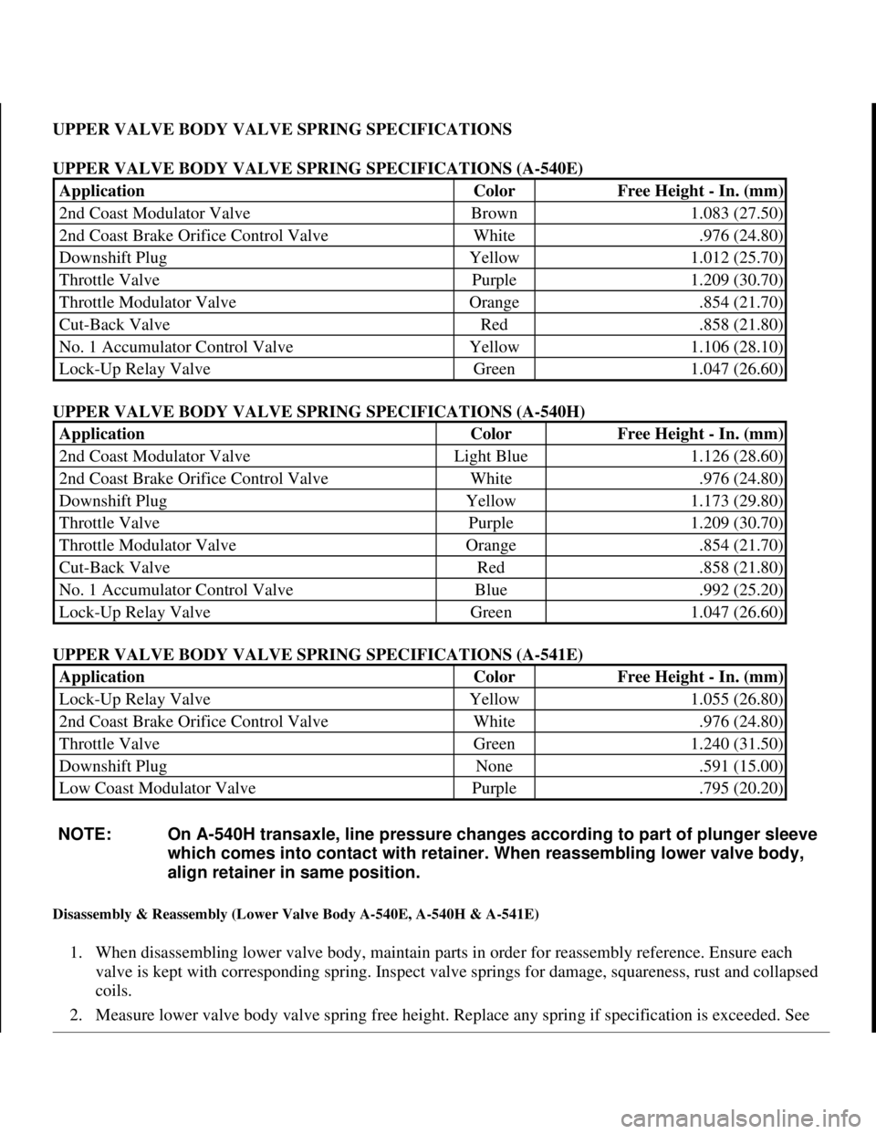
UPPER VALVE BODY VALVE SPRING SPECIFICATIONS
UPPER VALVE BODY VALVE SPRING SPECIFICATIONS (A-540E)
UPPER VALVE BODY VALVE SPRING SPECIFICATIONS (A-540H)
UPPER VALVE BODY VALVE SPRING SPECIFICATIONS (A-541E)
Disassembly & Reassembly (Lower Valve Body A-540E, A-540H & A-541E)
1. When disassembling lower valve body, maintain parts in order for reassembly reference. Ensure each
valve is kept with corresponding spring. Inspect valve springs for damage, squareness, rust and collapsed
coils.
2. Measure lower valve bod
y valve spring free height. Replace any spring if specification is exceeded. See
ApplicationColorFree Height - In. (mm)
2nd Coast Modulator ValveBrown1.083 (27.50)
2nd Coast Brake Orifice Control ValveWhite.976 (24.80)
Downshift PlugYellow1.012 (25.70)
Throttle ValvePurple1.209 (30.70)
Throttle Modulator ValveOrange.854 (21.70)
Cut-Back ValveRed.858 (21.80)
No. 1 Accumulator Control ValveYellow1.106 (28.10)
Lock-Up Relay ValveGreen1.047 (26.60)
ApplicationColorFree Height - In. (mm)
2nd Coast Modulator ValveLight Blue1.126 (28.60)
2nd Coast Brake Orifice Control ValveWhite.976 (24.80)
Downshift PlugYellow1.173 (29.80)
Throttle ValvePurple1.209 (30.70)
Throttle Modulator ValveOrange.854 (21.70)
Cut-Back ValveRed.858 (21.80)
No. 1 Accumulator Control ValveBlue.992 (25.20)
Lock-Up Relay ValveGreen1.047 (26.60)
ApplicationColorFree Height - In. (mm)
Lock-Up Relay ValveYellow1.055 (26.80)
2nd Coast Brake Orifice Control ValveWhite.976 (24.80)
Throttle ValveGreen1.240 (31.50)
Downshift PlugNone.591 (15.00)
Low Coast Modulator ValvePurple.795 (20.20)
NOTE: On A-540H transaxle, line pressure changes according to part of plunger sleeve
which comes into contact with retainer. When reassembling lower valve body,
align retainer in same position.
1998 Toyota Avalon XLS
1997-99 AUTOMATIC TRANSMISSIONS Toyota A-540E, A-540H & A-541E Overhaul
Helpmelearn
November-03-08 10:28:18 AMPage 52 © 2005 Mitchell Repair Information Company, LLC.
Page 619 of 1632
differential carrier. Install original washer onto drive pinion. Press rear bearing onto drive pinion.
9. Install drive pinion into carrier and install front drive pinion bearing. Check and adjust gear tooth contact
pattern. Assemble and install pinion spacer, oil slinger and NEW oil seal.
10. Press companion flange onto drive pinion. Coat threads of flange nut with grease. Adjusting drive pinion
preload by tightening nut, in increments, while holding flange. Tighten nut to reach starting preload of
8.7-13.9 INCH lbs. (1.0-1.6 N.m) if a NEW front bearing was installed, or 4.3-6.9 INCH lbs. (.5-.8 N.m)
if original bearing was installed.
11. Install differential case with ring gear and outer bearing races in differential carrier.
12. Install plate washer on ring gear back side only. Using a plastic hammer, tap on ring gear to snug down
washer and bearing. Using dial indicator, check ring gear backlash while rotating ring gear back and
forth, and holding drive pinion from rotating. See Fig. 7
.
13. Check ring gear backlash at 3 different areas on ring gear and record ring gear backlash. Ring gear
backlash should be .0051" (.129 mm).
14. If ring gear backlash is not within specifications, select ring gear back side plate washer to bring backlash
within specification. Select ring gear teeth side washer thick enough to eliminate any clearance between
outer race and differential case.
15. Remove teeth side plate washer and differential case. Install ring gear back side plate washer. Place outer
plate washer onto differential case, together with outer race. Install differential case with outer race into
carrier. Tap ring gear with plastic hammer to snug down washer and bearing.
16. With a dial indicator, re-measure ring gear backlash. It should be .0051-.0071" (.13-.18 mm). If not,
increase or decrease thickness of washers on both sides of ring gear by equal amount. Clearance should
exist between plate washer and case when backlash is within specification.
17. When ring gear backlash is properly adjusted, remove teeth side plate washer. With micrometer, measure
thickness of plate washer. Install NEW washer that is .0024-.0035" (.060-.088 mm) thicker than plate
washer removed. Washer should press into position about 2/3 way by hand. Use brass bar and hammer to
fully seat plate washer.
18. Align reference marks on bearing caps and carrier. Install bearing caps and tighten bolts to specification.
See TORQUE SPECIFICATIONS
. Ensure ring gear backlash is within specified range. If not, increase
or decrease thickness of washers on both sides of ring gear by equal amount.
19. Using INCH-lb. torque wrench installed on drive pinion nut, measure total assembled preload required to
rotate drive pinion and ring gear. Total assembled preload should equal amount of starting preload plus
2.6-4.3 INCH lbs. (.3-.5 N.m).
20. Check gear tooth contact pattern. See GEAR TOOTH CONTACT PATTERNS article in GENERAL
INFORMATION. If gear tooth contact pattern is incorrect, install different thickness adjusting washer
located in differential carrier, behind race for front bearin
g. Recheck gear tooth contact pattern. Adjusting CAUTION: When tightening drive pinion nut, DO NOT overtighten nut, as spacer
is not installed on drive pinion. Drive pinion nut must be tightened
until correct drive pinion rotating torque is obtained.
NOTE: Backlash will change about .0008" (.020 mm) for every .0012" (.030 mm)
change in plate washer thickness.
1999 Toyota RAV4
1999-2000 DRIVE AXLES Differentials, Axle Shafts & Drive Shafts -- Rear Integral Housing -- RAV4
Microsoft
Sunday, November 22, 2009 10:09:38 AMPage 14 © 2005 Mitchell Repair Information Company, LLC.
Page 945 of 1632
Normal Service
Driven More Than 10 Miles Daily
No Operating Conditions From Severe Service Schedule
Severe Service (Unique Driving Conditions)
CAMSHAFT TIMING BELT
Inspect timing belt at 60,000 miles or 48 months and thereafter inspect timing belt every 15,000 miles, or 12
months. Replace belt as necessary.
The condition of camshaft drive belts should always be checked on vehicles which have more than 50,000
miles. Although some manufacturers do not recommend belt replacement at a specified mileage, others require
it at 60,000-100,000 miles. A camshaft drive belt failure may cause extensive damage to internal engine
components on most engines, although some designs do not allow piston-to-valve contact. These designs are
often called Free Wheeling.
Many manufacturers changed their maintenance and warranty schedules in the mid-1980's to reflect timing belt
inspection and/or replacement at 50,000-60,000 miles. Most service interval schedules in this manual reflect
these changes.
Belts or components should be inspected and replaced if any of the following conditions exist:
Cracks Or Tears In Belt Surface
Missing, Damaged, Cracked Or Rounded Teeth
Oil Contamination
Damaged Or Faulty Tensioners
Incorrect Tension Adjustment NOTE: Use the Severe Service schedule if the vehicle to be serviced is operated under
ANY (one or more) of these conditions:
Towing a trailer or using a camper or car-top carrier.
Repeated short trips of less than 5 miles in temperatures below freezing.
Extensive idling or low-speed driving for long distances as in heavy
commercial use such as delivery, taxi or patrol car.
Operating on rough, muddy or salt covered roads.
Operating on unpaved or dusty roads.
CAUTION: Failure to replace a faulty camshaft timing belt may result in serious
engine damage.
1999 Toyota RAV4
MAINTENANCE INFORMATION 1997-99 MAINTENANCE Toyota Maintenance Information
Microsoft
Sunday, November 22, 2009 10:32:41 AMPage 3 © 2005 Mitchell Repair Information Company, LLC.
Page 998 of 1632
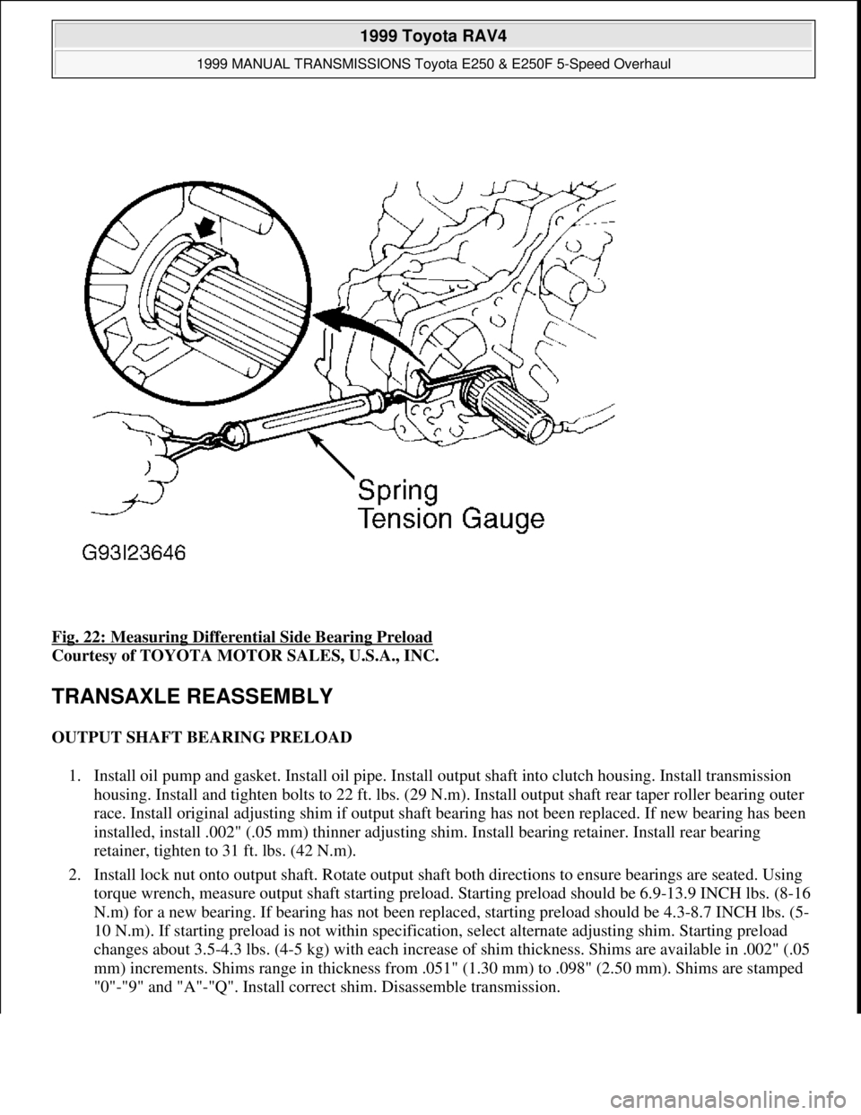
Fig. 22: Measuring Differential Side Bearing Preload
Courtesy of TOYOTA MOTOR SALES, U.S.A., INC.
TRANSAXLE REASSEMBLY
OUTPUT SHAFT BEARING PRELOAD
1. Install oil pump and gasket. Install oil pipe. Install output shaft into clutch housing. Install transmission
housing. Install and tighten bolts to 22 ft. lbs. (29 N.m). Install output shaft rear taper roller bearing outer
race. Install original adjusting shim if output shaft bearing has not been replaced. If new bearing has been
installed, install .002" (.05 mm) thinner adjusting shim. Install bearing retainer. Install rear bearing
retainer, tighten to 31 ft. lbs. (42 N.m).
2. Install lock nut onto output shaft. Rotate output shaft both directions to ensure bearings are seated. Using
torque wrench, measure output shaft starting preload. Starting preload should be 6.9-13.9 INCH lbs. (8-16
N.m) for a new bearing. If bearing has not been replaced, starting preload should be 4.3-8.7 INCH lbs. (5-
10 N.m). If starting preload is not within specification, select alternate adjusting shim. Starting preload
changes about 3.5-4.3 lbs. (4-5 kg) with each increase of shim thickness. Shims are available in .002" (.05
mm) increments. Shims range in thickness from .051" (1.30 mm) to .098" (2.50 mm). Shims are stamped
"0"-"9" and "A"-"Q". Install correct shim. Disassemble transmission.
1999 Toyota RAV4
1999 MANUAL TRANSMISSIONS Toyota E250 & E250F 5-Speed Overhaul
Microsoft
Sunday, November 22, 2009 10:48:07 AMPage 28 © 2005 Mitchell Repair Information Company, LLC.