fuel pump TOYOTA RAV4 1996 Service Repair Manual
[x] Cancel search | Manufacturer: TOYOTA, Model Year: 1996, Model line: RAV4, Model: TOYOTA RAV4 1996Pages: 1632, PDF Size: 41.64 MB
Page 675 of 1632
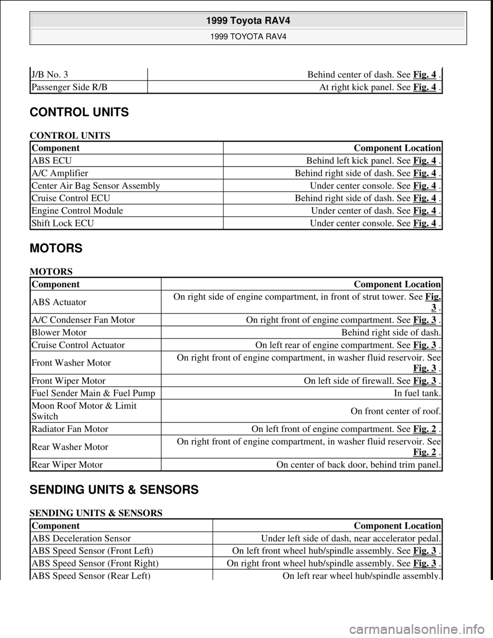
CONTROL UNITS
CONTROL UNITS
MOTORS
MOTORS
SENDING UNITS & SENSORS
SENDING UNITS & SENSORS
J/B No. 3Behind center of dash. See Fig. 4 .
Passenger Side R/BAt right kick panel. See Fig. 4 .
ComponentComponent Location
ABS ECUBehind left kick panel. See Fig. 4 .
A/C AmplifierBehind right side of dash. See Fig. 4 .
Center Air Bag Sensor AssemblyUnder center console. See Fig. 4 .
Cruise Control ECUBehind right side of dash. See Fig. 4 .
Engine Control ModuleUnder center of dash. See Fig. 4 .
Shift Lock ECUUnder center console. See Fig. 4 .
ComponentComponent Location
ABS ActuatorOn right side of engine compartment, in front of strut tower. See Fig.
3 .
A/C Condenser Fan MotorOn right front of engine compartment. See Fig. 3 .
Blower MotorBehind right side of dash.
Cruise Control ActuatorOn left rear of engine compartment. See Fig. 3 .
Front Washer MotorOn right front of engine compartment, in washer fluid reservoir. See
Fig. 3
.
Front Wiper MotorOn left side of firewall. See Fig. 3 .
Fuel Sender Main & Fuel PumpIn fuel tank.
Moon Roof Motor & Limit
SwitchOn front center of roof.
Radiator Fan MotorOn left front of engine compartment. See Fig. 2 .
Rear Washer MotorOn right front of engine compartment, in washer fluid reservoir. See
Fig. 2
.
Rear Wiper MotorOn center of back door, behind trim panel.
ComponentComponent Location
ABS Deceleration SensorUnder left side of dash, near accelerator pedal.
ABS Speed Sensor (Front Left)On left front wheel hub/spindle assembly. See Fig. 3 .
ABS Speed Sensor (Front Right)On right front wheel hub/spindle assembly. See Fig. 3 .
ABS Speed Sensor (Rear Left)On left rear wheel hub/spindle assembly.
1999 Toyota RAV4
1999 TOYOTA RAV4
Microsoft
Sunday, November 22, 2009 10:17:32 AMPage 2 © 2005 Mitchell Repair Information Company, LLC.
Page 676 of 1632
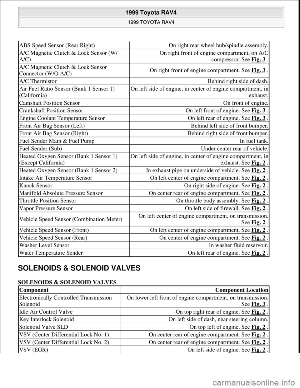
SOLENOIDS & SOLENOID VALVES
SOLENOIDS & SOLENOID VALVES
ABS Speed Sensor (Rear Right)On right rear wheel hub/spindle assembly.
A/C Magnetic Clutch & Lock Sensor (W/
A/C)On right front of engine compartment, on A/C
compressor. See Fig. 3
.
A/C Magnetic Clutch & Lock Sensor
Connector (W/O A/C)On right front of engine compartment. See Fig. 3 .
A/C ThermistorBehind right side of dash.
Air Fuel Ratio Sensor (Bank 1 Sensor 1)
(California)On left side of engine, in center of engine compartment, in
exhaust.
Camshaft Position SensorOn front of engine.
Crankshaft Position SensorOn left front of engine. See Fig. 3 .
Engine Coolant Temperature SensorOn left rear of engine. See Fig. 3 .
Front Air Bag Sensor (Left)Behind left side of front bumper.
Front Air Bag Sensor (Right)Behind right side of front bumper.
Fuel Sender Main & Fuel PumpIn fuel tank.
Fuel Sender (Sub)Under center rear of vehicle.
Heated Oxygen Sensor (Bank 1 Sensor 1)
(Except California)On left side of engine, in center of engine compartment, in
exhaust. See Fig. 2
.
Heated Oxygen Sensor (Bank 1 Sensor 2)In exhaust pipe on underside of vehicle. See Fig. 2 .
Intake Air Temperature SensorOn left center of engine compartment. See Fig. 2 .
Knock SensorOn right side of engine. See Fig. 2 .
Manifold Absolute Pressure SensorOn center rear of engine compartment. See Fig. 2 .
Throttle Position SensorOn throttle body assembly. See Fig. 2 .
Vapor Pressure SensorOn left side of firewall. See Fig. 2 .
Vehicle Speed Sensor (Combination Meter)On left center of engine compartment, on transmission.
See Fig. 2
.
Vehicle Speed Sensor (Front)On left center of engine compartment. See Fig. 2 .
Vehicle Speed Sensor (Rear)On center of engine compartment. See Fig. 2 .
Washer Level SensorIn washer fluid reservoir.
Water Temperature SenderOn left rear of engine. See Fig. 2 .
ComponentComponent Location
Electronically Controlled Transmission
SolenoidOn lower left front of engine compartment, on transmission.
See Fig. 3
.
Idle Air Control ValveOn top right rear of engine. See Fig. 2 .
Key Interlock SolenoidOn left side of dash, near steering column.
Solenoid Valve SLDOn top left of engine. See Fig. 2 .
VSV (Center Differential Lock No. 1)On center rear of engine compartment. See Fig. 2 .
VSV (Center Differential Lock No. 2)On center rear of engine compartment. See Fig. 2 .
VSV (EGR)On left side of engine. See Fig. 2 .
1999 Toyota RAV4
1999 TOYOTA RAV4
Microsoft
Sunday, November 22, 2009 10:17:32 AMPage 3 © 2005 Mitchell Repair Information Company, LLC.
Page 693 of 1632
1. Remove driver-side rear seat and floor panel cover for access to fuel pump electrical connector.
2. Disconnect fuel pump electrical connector. Start engine and allow engine to idle until engine stalls. Turn
ignition off.
3. Reconnect fuel pump electrical connector. Reinstall floor panel cover and driver-side rear seat.
4. Disconnect negative battery cable. Place an approved gasoline container under fuel line. Cover fuel line
connection with shop towel.
5. Slowly loosen fuel line connection to release fuel pressure. Once fuel pressure is released, fuel system
components may be serviced.
ENGINE
Removal
1. Engine and transaxle are removed as an assembly from bottom of engine compartment. Release fuel
pressure. See FUEL PRESSURE RELEASE
. Remove hood, battery and battery tray. Drain cooling
system, and engine and transaxle oil.
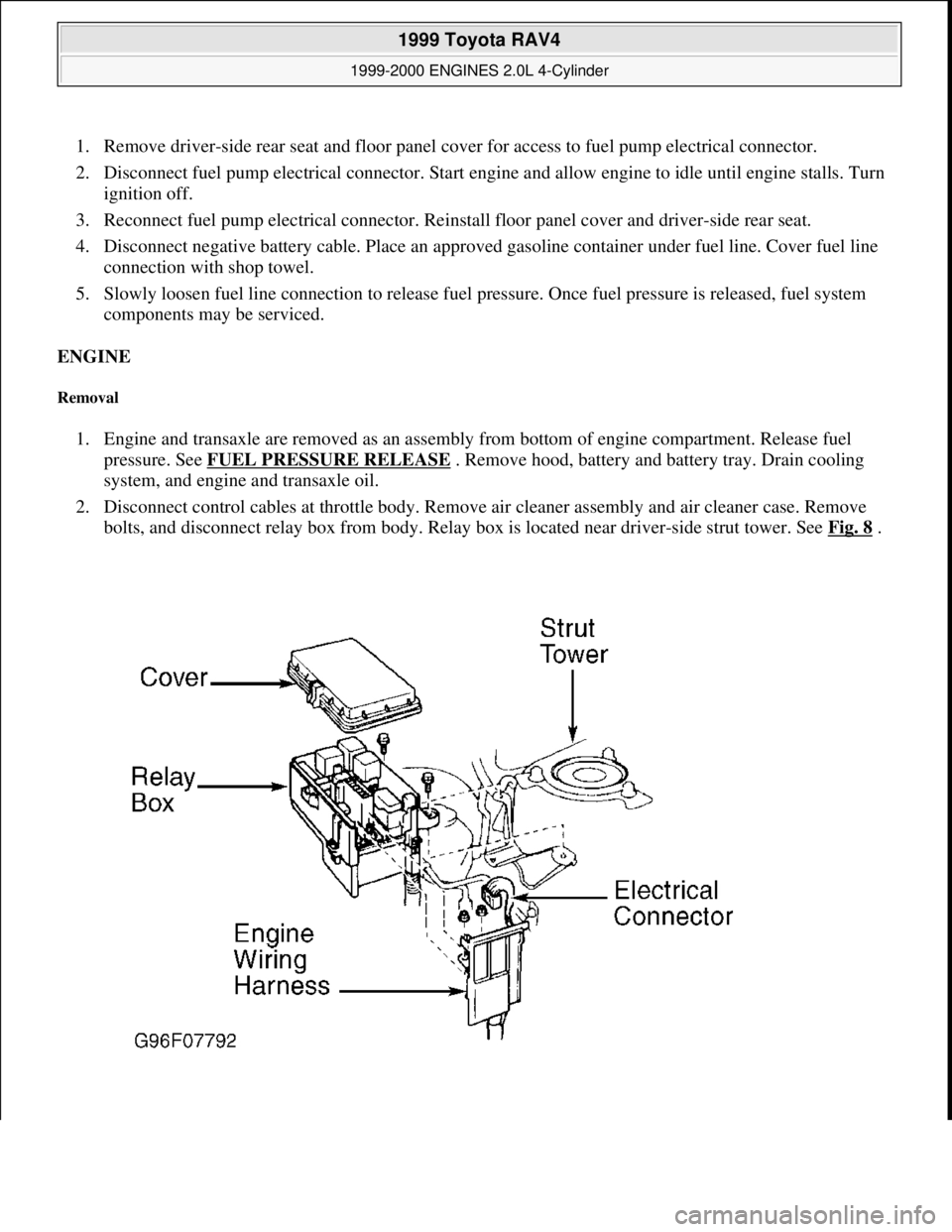
2. Disconnect control cables at throttle body. Remove air cleaner assembly and air cleaner case. Remove
bolts, and disconnect relay box from body. Relay box is located near driver-side strut tower. See Fig. 8
.
1999 Toyota RAV4
1999-2000 ENGINES 2.0L 4-Cylinder
Microsoft
Sunday, November 22, 2009 10:22:26 AMPage 10 © 2005 Mitchell Repair Information Company, LLC.
Page 705 of 1632
control cable to intake manifold. On all models, install NEW gasket and EGR valve with union nut and 2
nuts. Install vacuum modulator to clamp on intake manifold. Connect vacuum hoses to EGR VSV.
Connect fuel inlet hose to fuel filter
14. Connect vacuum sensor hose to gas filter, and brake booster vacuum hose to intake manifold. Install
throttle body. Install NEW "O" ring on coolant by-pass pipe, and NEW gasket on water pump cover
before installing coolant by-pass pipe. Apply soapy water solution to "O" ring before installing coolant
by-pass pipe. Install by-pass pipe.
15. Install NEW gasket and water outlet. Connect radiator, water by-pass and heater water hoses. Connect
ECT sensor and sender gauge connectors. Connect oil pressure switch.
16. Install ignition coils, manifold stay and spark plug wires. Connect wire clamp to manifold stay. Connect
spark plug wires to spark plugs and clamps on cylinder head cover. Connect ignition coil connectors.
17. Install 2 heat insulators. Install lower heat insulator. On California models, install A/F sensor to exhaust
manifold. All others, install oxygen sensor (bank 1 sensor 1) to exhaust manifold.
18. Using a new gasket, install exhaust manifold and heat insulator assembly. Install right-side exhaust
manifolds stay (California). Install left-side exhaust manifold stay. Install upper manifold heat insulator.
Connect A/F sensor connectors (California), or Oxygen sensor (bank 1 sensor 1).
19. Use NEW gasket and NEW nuts when installing front exhaust pipe. Ensure all bolts/nuts are loosely
installed on front exhaust pipe before tightening to specification. See TORQUE SPECIFICATIONS
20. Install generator and air cleaner and cap. Connect accelerator cable to throttle body and cable bracket. On
A/T models, connect throttle cable to throttle body and cable bracket. On all models, start engine and
check for leaks. Recheck engine coolant and oil level. Install right-side engine undercover.
CRANKSHAFT FRONT SEAL
Removal & Installation (Oil Pump Installed)
1. Remove timing belt and crankshaft sprocket. See TIMING BELT . Using a knife, cut lip from seal. Pry
seal from oil pump housing. DO NOT damage sealing surfaces.
2. To install, apply grease to lip of new seal. Using hammer and Seal Installer (SST 09226-10010), install
seal until seal surface is even with oil pump housing. To install remaining components, reverse removal
procedure.
Removal & Installation (Oil Pump Removed)
Using hammer and drift, remove seal from oil pump housing. To install, use hammer and Seal Installer (SST
09226-10010). Install seal until seal surface is even with oil pump housing. Apply grease to lip of new seal.
TIMING BELT
CAUTION: If reusing timing belt, mark direction of timing belt rotation, and place
reference mark on timing belt at camshaft sprocket for reassembly
reference. Also, place reference mark on timing belt at upper edge of No. 1
timing belt cover. DO NOT bend, twist or turn timing belt inside-out. DO
NOT expose timing to oil, water or steam.
1999 Toyota RAV4
1999-2000 ENGINES 2.0L 4-Cylinder
Microsoft
Sunday, November 22, 2009 10:22:26 AMPage 22 © 2005 Mitchell Repair Information Company, LLC.
Page 741 of 1632
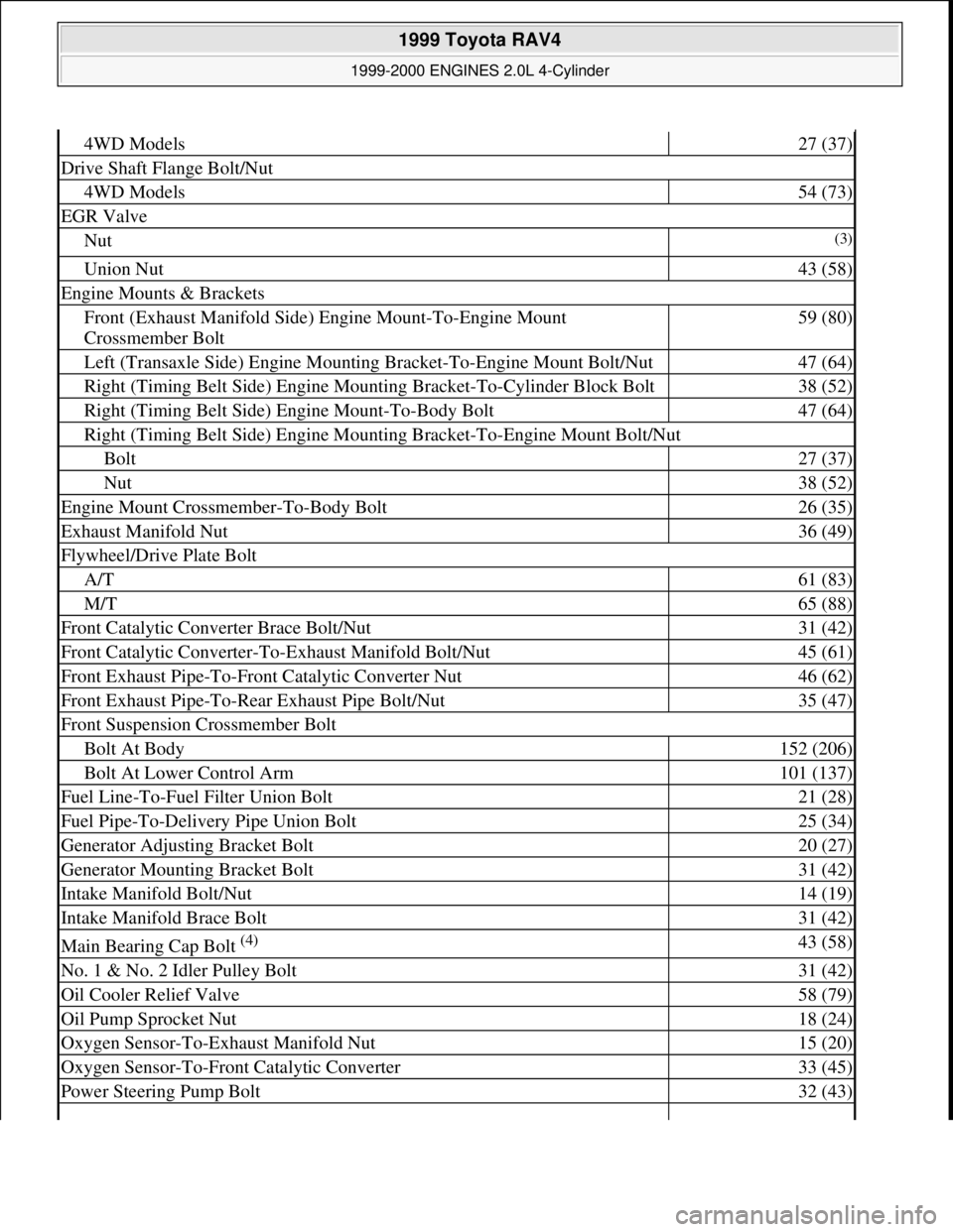
4WD Models27 (37)
Drive Shaft Flange Bolt/Nut
4WD Models54 (73)
EGR Valve
Nut(3)
Union Nut43 (58)
Engine Mounts & Brackets
Front (Exhaust Manifold Side) Engine Mount-To-Engine Mount
Crossmember Bolt59 (80)
Left (Transaxle Side) Engine Mounting Bracket-To-Engine Mount Bolt/Nut47 (64)
Right (Timing Belt Side) Engine Mounting Bracket-To-Cylinder Block Bolt38 (52)
Right (Timing Belt Side) Engine Mount-To-Body Bolt47 (64)
Right (Timing Belt Side) Engine Mounting Bracket-To-Engine Mount Bolt/Nut
Bolt27 (37)
Nut38 (52)
Engine Mount Crossmember-To-Body Bolt26 (35)
Exhaust Manifold Nut36 (49)
Flywheel/Drive Plate Bolt
A/T61 (83)
M/T65 (88)
Front Catalytic Converter Brace Bolt/Nut31 (42)
Front Catalytic Converter-To-Exhaust Manifold Bolt/Nut45 (61)
Front Exhaust Pipe-To-Front Catalytic Converter Nut46 (62)
Front Exhaust Pipe-To-Rear Exhaust Pipe Bolt/Nut35 (47)
Front Suspension Crossmember Bolt
Bolt At Body152 (206)
Bolt At Lower Control Arm101 (137)
Fuel Line-To-Fuel Filter Union Bolt21 (28)
Fuel Pipe-To-Delivery Pipe Union Bolt25 (34)
Generator Adjusting Bracket Bolt20 (27)
Generator Mounting Bracket Bolt31 (42)
Intake Manifold Bolt/Nut14 (19)
Intake Manifold Brace Bolt31 (42)
Main Bearing Cap Bolt (4) 43 (58)
No. 1 & No. 2 Idler Pulley Bolt31 (42)
Oil Cooler Relief Valve58 (79)
Oil Pump Sprocket Nut18 (24)
Oxygen Sensor-To-Exhaust Manifold Nut15 (20)
Oxygen Sensor-To-Front Catalytic Converter33 (45)
Power Steering Pump Bolt32 (43)
1999 Toyota RAV4
1999-2000 ENGINES 2.0L 4-Cylinder
Microsoft
Sunday, November 22, 2009 10:22:27 AMPage 58 © 2005 Mitchell Repair Information Company, LLC.
Page 742 of 1632
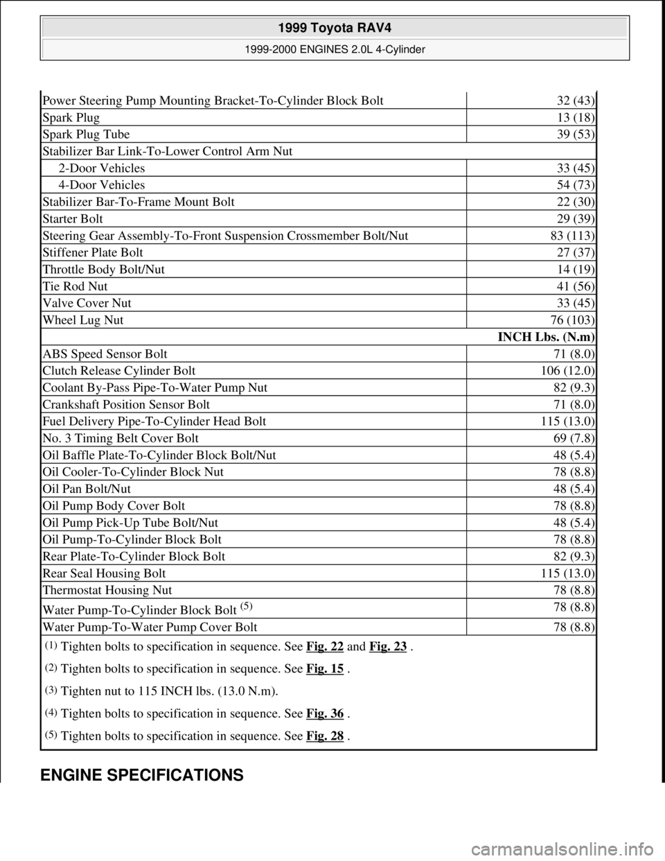
ENGINE SPECIFICATIONS
Power Steering Pump Mounting Bracket-To-Cylinder Block Bolt32 (43)
Spark Plug13 (18)
Spark Plug Tube39 (53)
Stabilizer Bar Link-To-Lower Control Arm Nut
2-Door Vehicles33 (45)
4-Door Vehicles54 (73)
Stabilizer Bar-To-Frame Mount Bolt22 (30)
Starter Bolt29 (39)
Steering Gear Assembly-To-Front Suspension Crossmember Bolt/Nut 83 (113)
Stiffener Plate Bolt27 (37)
Throttle Body Bolt/Nut14 (19)
Tie Rod Nut41 (56)
Valve Cover Nut33 (45)
Wheel Lug Nut76 (103)
INCH Lbs. (N.m)
ABS Speed Sensor Bolt71 (8.0)
Clutch Release Cylinder Bolt106 (12.0)
Coolant By-Pass Pipe-To-Water Pump Nut82 (9.3)
Crankshaft Position Sensor Bolt71 (8.0)
Fuel Delivery Pipe-To-Cylinder Head Bolt115 (13.0)
No. 3 Timing Belt Cover Bolt69 (7.8)
Oil Baffle Plate-To-Cylinder Block Bolt/Nut48 (5.4)
Oil Cooler-To-Cylinder Block Nut78 (8.8)
Oil Pan Bolt/Nut48 (5.4)
Oil Pump Body Cover Bolt78 (8.8)
Oil Pump Pick-Up Tube Bolt/Nut48 (5.4)
Oil Pump-To-Cylinder Block Bolt78 (8.8)
Rear Plate-To-Cylinder Block Bolt82 (9.3)
Rear Seal Housing Bolt115 (13.0)
Thermostat Housing Nut78 (8.8)
Water Pump-To-Cylinder Block Bolt (5) 78 (8.8)
Water Pump-To-Water Pump Cover Bolt78 (8.8)
(1)Tighten bolts to specification in sequence. See Fig. 22 and Fig. 23 .
(2)Tighten bolts to specification in sequence. See Fig. 15 .
(3)Tighten nut to 115 INCH lbs. (13.0 N.m).
(4)Tighten bolts to specification in sequence. See Fig. 36 .
(5)Tighten bolts to specification in sequence. See Fig. 28 .
1999 Toyota RAV4
1999-2000 ENGINES 2.0L 4-Cylinder
Microsoft
Sunday, November 22, 2009 10:22:27 AMPage 59 © 2005 Mitchell Repair Information Company, LLC.
Page 758 of 1632
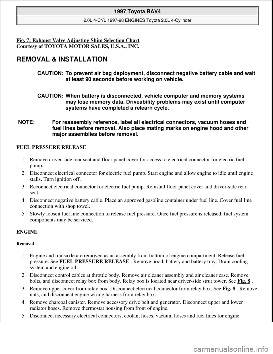
Fig. 7: Exhaust Valve Adjusting Shim Selection Chart
Courtesy of TOYOTA MOTOR SALES, U.S.A., INC.
REMOVAL & INSTALLATION
FUEL PRESSURE RELEASE
1. Remove driver-side rear seat and floor panel cover for access to electrical connector for electric fuel
pump.
2. Disconnect electrical connector for electric fuel pump. Start engine and allow engine to idle until engine
stalls. Turn ignition off.
3. Reconnect electrical connector for electric fuel pump. Reinstall floor panel cover and driver-side rear
seat.
4. Disconnect negative battery cable. Place an approved gasoline container under fuel line. Cover fuel line
connection with shop towel.
5. Slowly loosen fuel line connection to release fuel pressure. Once fuel pressure is released, fuel system
components may be serviced.
ENGINE
Removal
1. Engine and transaxle are removed as an assembly from bottom of engine compartment. Release fuel
pressure. See FUEL PRESSURE RELEASE
. Remove hood, battery and battery tray. Drain cooling
system and engine oil.
2. Disconnect control cables at throttle body. Remove air cleaner assembly and air cleaner case. Remove
bolts, and disconnect relay box from body. Relay box is located near driver-side strut tower. See Fig. 8
.
3. Remove upper cover from relay box. Disconnect electrical connector from relay box. See Fig. 8
. Remove
nuts, and disconnect engine wiring harness from relay box.
4. Remove charcoal canister. Remove accessory drive belt and generator. Disconnect upper and lower
radiator hoses. Remove thermostat housing from front of engine.
5. Disconnect necessar
y electrical connectors, coolant hoses, vacuum hoses and fuel lines for engine CAUTION: To prevent air bag deployment, disconnect negative battery cable and wait
at least 90 seconds before working on vehicle.
CAUTION: When battery is disconnected, vehicle computer and memory systems
may lose memory data. Driveability problems may exist until computer
systems have completed a relearn cycle.
NOTE: For reassembly reference, label all electrical connectors, vacuum hoses and
fuel lines before removal. Also place mating marks on engine hood and other
major assemblies before removal.
1997 Toyota RAV4
2.0L 4-CYL 1997-98 ENGINES Toyota 2.0L 4-Cylinder
Microsoft
Sunday, November 22, 2009 10:23:30 AMPage 10 © 2005 Mitchell Repair Information Company, LLC.
Page 769 of 1632
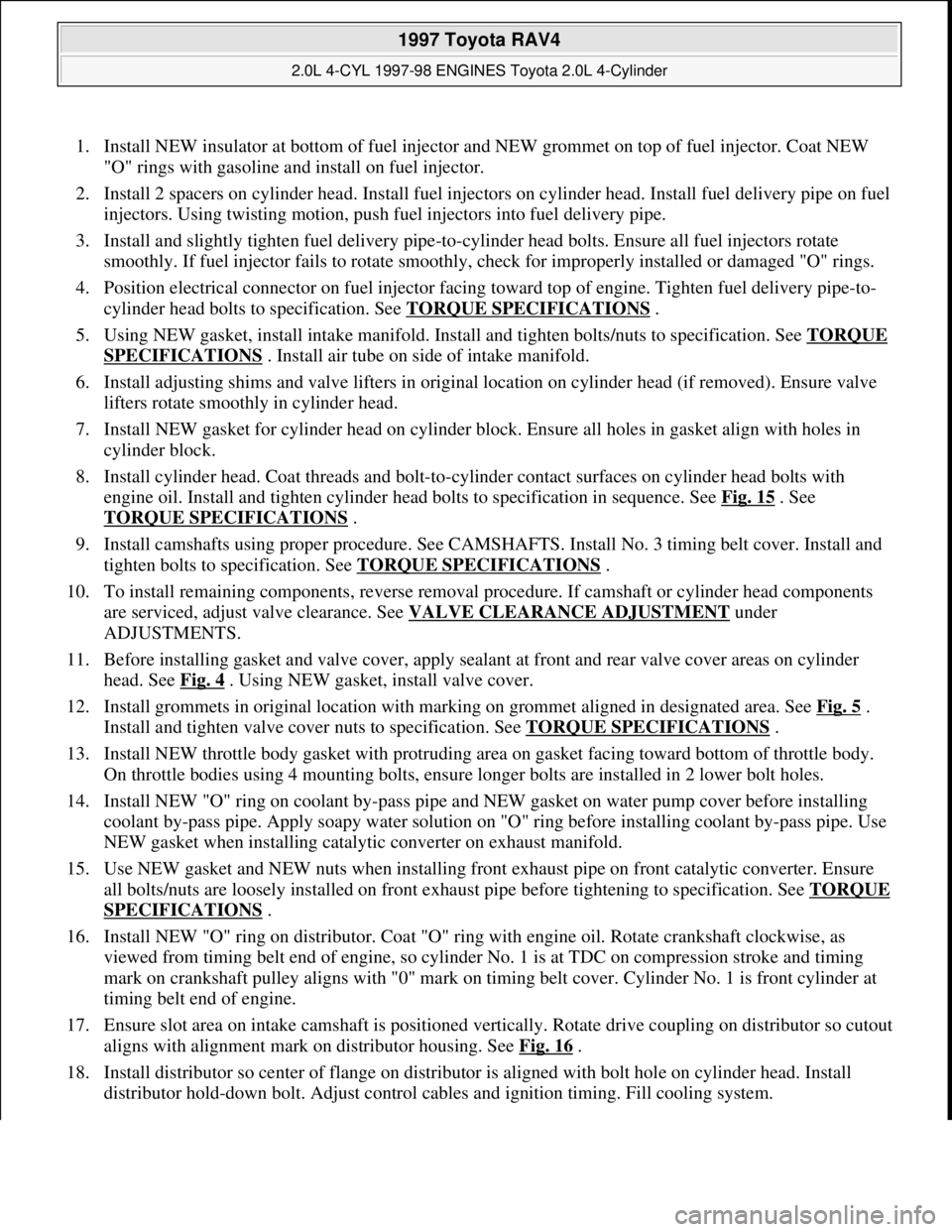
1. Install NEW insulator at bottom of fuel injector and NEW grommet on top of fuel injector. Coat NEW
"O" rings with gasoline and install on fuel injector.
2. Install 2 spacers on cylinder head. Install fuel injectors on cylinder head. Install fuel delivery pipe on fuel
injectors. Using twisting motion, push fuel injectors into fuel delivery pipe.
3. Install and slightly tighten fuel delivery pipe-to-cylinder head bolts. Ensure all fuel injectors rotate
smoothly. If fuel injector fails to rotate smoothly, check for improperly installed or damaged "O" rings.
4. Position electrical connector on fuel injector facing toward top of engine. Tighten fuel delivery pipe-to-
cylinder head bolts to specification. See TORQUE SPECIFICATIONS
.
5. Using NEW gasket, install intake manifold. Install and tighten bolts/nuts to specification. See TORQUE
SPECIFICATIONS . Install air tube on side of intake manifold.
6. Install adjusting shims and valve lifters in original location on cylinder head (if removed). Ensure valve
lifters rotate smoothly in cylinder head.
7. Install NEW gasket for cylinder head on cylinder block. Ensure all holes in gasket align with holes in
cylinder block.
8. Install cylinder head. Coat threads and bolt-to-cylinder contact surfaces on cylinder head bolts with
engine oil. Install and tighten cylinder head bolts to specification in sequence. See Fig. 15
. See
TORQUE SPECIFICATIONS
.
9. Install camshafts using proper procedure. See CAMSHAFTS. Install No. 3 timing belt cover. Install and
tighten bolts to specification. See TORQUE SPECIFICATIONS
.
10. To install remaining components, reverse removal procedure. If camshaft or cylinder head components
are serviced, adjust valve clearance. See VALVE CLEARANCE ADJUSTMENT
under
ADJUSTMENTS.
11. Before installing gasket and valve cover, apply sealant at front and rear valve cover areas on cylinder
head. See Fig. 4
. Using NEW gasket, install valve cover.
12. Install grommets in original location with marking on grommet aligned in designated area. See Fig. 5
.
Install and tighten valve cover nuts to specification. See TORQUE SPECIFICATIONS
.
13. Install NEW throttle body gasket with protruding area on gasket facing toward bottom of throttle body.
On throttle bodies using 4 mounting bolts, ensure longer bolts are installed in 2 lower bolt holes.
14. Install NEW "O" ring on coolant by-pass pipe and NEW gasket on water pump cover before installing
coolant by-pass pipe. Apply soapy water solution on "O" ring before installing coolant by-pass pipe. Use
NEW gasket when installing catalytic converter on exhaust manifold.
15. Use NEW gasket and NEW nuts when installing front exhaust pipe on front catalytic converter. Ensure
all bolts/nuts are loosely installed on front exhaust pipe before tightening to specification. See TORQUE
SPECIFICATIONS .
16. Install NEW "O" ring on distributor. Coat "O" ring with engine oil. Rotate crankshaft clockwise, as
viewed from timing belt end of engine, so cylinder No. 1 is at TDC on compression stroke and timing
mark on crankshaft pulley aligns with "0" mark on timing belt cover. Cylinder No. 1 is front cylinder at
timing belt end of engine.
17. Ensure slot area on intake camshaft is positioned vertically. Rotate drive coupling on distributor so cutout
aligns with alignment mark on distributor housing. See Fig. 16
.
18. Install distributor so center of flange on distributor is aligned with bolt hole on cylinder head. Install
distributor hol
d-down bolt. Adjust control cables and ignition timing. Fill cooling system.
1997 Toyota RAV4
2.0L 4-CYL 1997-98 ENGINES Toyota 2.0L 4-Cylinder
Microsoft
Sunday, November 22, 2009 10:23:31 AMPage 21 © 2005 Mitchell Repair Information Company, LLC.
Page 810 of 1632
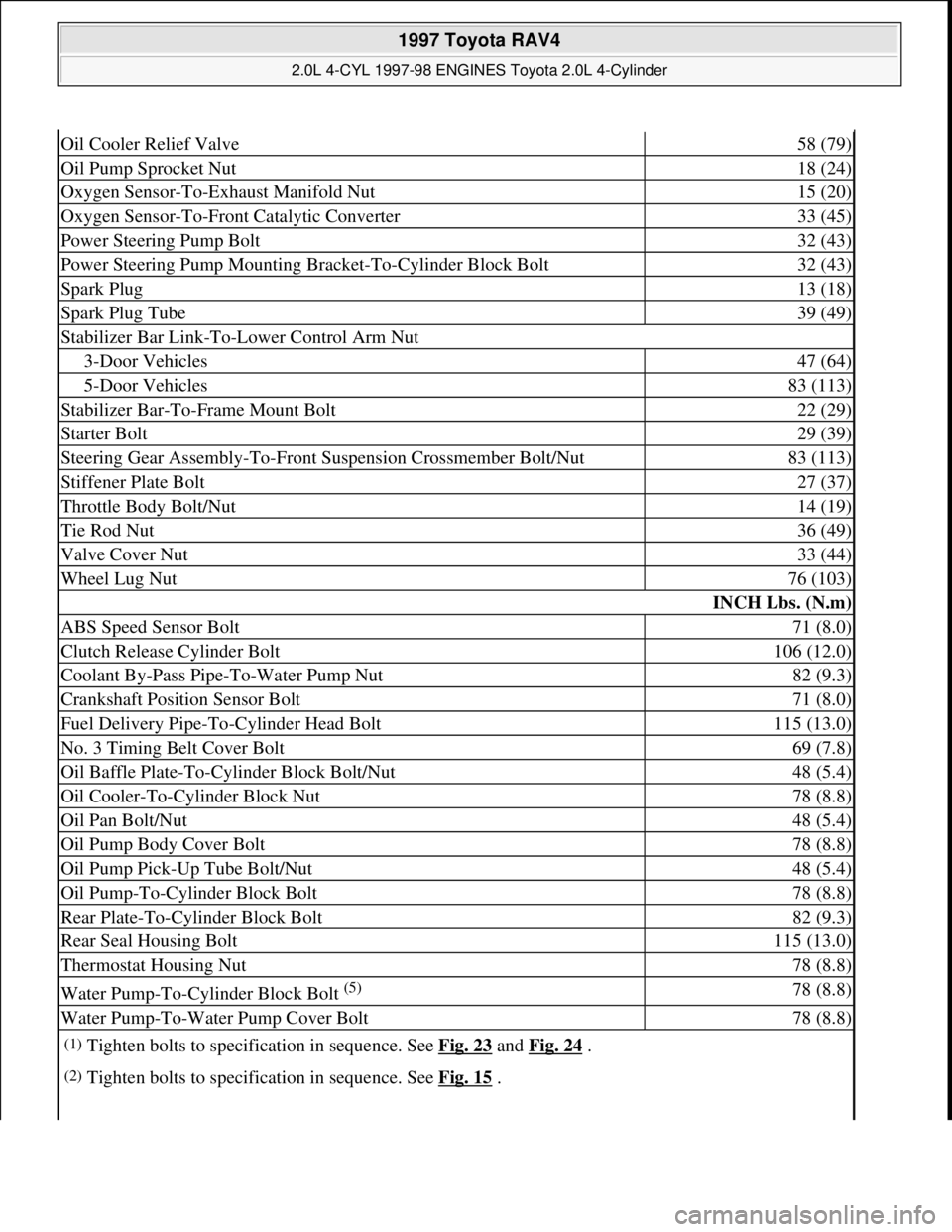
Oil Cooler Relief Valve58 (79)
Oil Pump Sprocket Nut18 (24)
Oxygen Sensor-To-Exhaust Manifold Nut15 (20)
Oxygen Sensor-To-Front Catalytic Converter33 (45)
Power Steering Pump Bolt32 (43)
Power Steering Pump Mounting Bracket-To-Cylinder Block Bolt32 (43)
Spark Plug13 (18)
Spark Plug Tube39 (49)
Stabilizer Bar Link-To-Lower Control Arm Nut
3-Door Vehicles47 (64)
5-Door Vehicles83 (113)
Stabilizer Bar-To-Frame Mount Bolt22 (29)
Starter Bolt29 (39)
Steering Gear Assembly-To-Front Suspension Crossmember Bolt/Nut83 (113)
Stiffener Plate Bolt27 (37)
Throttle Body Bolt/Nut14 (19)
Tie Rod Nut36 (49)
Valve Cover Nut33 (44)
Wheel Lug Nut76 (103)
INCH Lbs. (N.m)
ABS Speed Sensor Bolt71 (8.0)
Clutch Release Cylinder Bolt106 (12.0)
Coolant By-Pass Pipe-To-Water Pump Nut82 (9.3)
Crankshaft Position Sensor Bolt71 (8.0)
Fuel Delivery Pipe-To-Cylinder Head Bolt115 (13.0)
No. 3 Timing Belt Cover Bolt69 (7.8)
Oil Baffle Plate-To-Cylinder Block Bolt/Nut48 (5.4)
Oil Cooler-To-Cylinder Block Nut78 (8.8)
Oil Pan Bolt/Nut48 (5.4)
Oil Pump Body Cover Bolt78 (8.8)
Oil Pump Pick-Up Tube Bolt/Nut48 (5.4)
Oil Pump-To-Cylinder Block Bolt78 (8.8)
Rear Plate-To-Cylinder Block Bolt82 (9.3)
Rear Seal Housing Bolt115 (13.0)
Thermostat Housing Nut78 (8.8)
Water Pump-To-Cylinder Block Bolt (5) 78 (8.8)
Water Pump-To-Water Pump Cover Bolt78 (8.8)
(1)Tighten bolts to specification in sequence. See Fig. 23 and Fig. 24 .
(2)Tighten bolts to specification in sequence. See Fig. 15 .
1997 Toyota RAV4
2.0L 4-CYL 1997-98 ENGINES Toyota 2.0L 4-Cylinder
Microsoft
Sunday, November 22, 2009 10:23:31 AMPage 62 © 2005 Mitchell Repair Information Company, LLC.