height TOYOTA RAV4 1996 Service Repair Manual
[x] Cancel search | Manufacturer: TOYOTA, Model Year: 1996, Model line: RAV4, Model: TOYOTA RAV4 1996Pages: 1632, PDF Size: 41.64 MB
Page 26 of 1632
1. Check charging system voltage. Ensure 10-14 volts is present. If charging system voltage is okay, go to
next step. If charging system voltage is not okay, check and repair charging system.
2. Turn ignition switch to ON position. Ensure ABS warning light comes on, then goes out after 3 seconds.
If ABS warning light does not illuminate, check fuse, bulb, and wiring harness. See ABS WARNING
LIGHT under DIAGNOSIS & TESTING. Turn ignition off.
3. Using a jumper wire, jumper terminals Ts and E
1 of DLC1. DLC1 is located in engine compartment on
left side of engine. See Fig. 2
. Ensure ABS warning light blinks 4 times per second. If ABS light does
not blink, go to ABS WARNING LIGHT
under DIAGNOSIS & TESTING. If ABS warning light
blinks, go to next step.
4. Using a floor jack, slowly jack up rear of vehicle. On vehicles with 215/70R16 tires, raise vehicle to a
height of 25.59-27.95" (650-710 mm). On vehicles with 235/60R16 tires, raise vehicle to a height of
26.38-28.74" (670-730 mm). If ABS warning light illuminates at specified height, check deceleration
sensor installation. If installation is okay, replace deceleration sensor. Lower vehicle.
5. Using a floor jack, slowly jack up front of vehicle. On vehicles with 215/70R16 tires, raise vehicle to a
height of 21.20-23.56" (550-610 mm). On vehicles with 235/60R16 tires, raise vehicle to a height of
22.44-24.80" (570-630 mm). If ABS warning light illuminates at specified height, check deceleration
sensor installation. If installation is okay, replace deceleration sensor. Lower vehicle.
6. Drive vehicle straight ahead at speed of 13 MPH or more. Lightly depress brake pedal. Ensure ABS
warning light pattern is normal (light blinks 4 times per second).
7. While driving vehicle straight ahead at speed of 13 MPH or more, moderately depress brake pedal.
Ensure ABS warning light illuminates in a solid pattern (light does not blink) while braking.
8. While driving vehicle straight ahead at speed of 13 MPH or more, firmly depress brake pedal. Ensure
ABS warning light illumination pattern changes from a solid pattern (light does not blink) to a normal
pattern (light blinks 4 times per second), then back to a solid pattern while braking.
9. If ABS warning light does not illuminate as described in steps 6 -8 , check deceleration sensor
installation. If installation is okay, replace deceleration sensor. Stop vehicle and turn ignition off. Remove
jumper wire from DLC1.
REMOVAL & INSTALLATION
ACTUATOR
Removal & Installation
Turn ignition off. Disconnect brakelines attached to actuator. Remove power steering hose retaining bracket
bolt and power steering reservoir. Disconnect actuator electrical connectors. Remove bolts, nuts and washers.
Remove actuator assembly. Remove actuator from actuator bracket. Remove cushions and holders from NOTE: When measuring vehicle height in following steps, measure at center of
lower body of vehicle.
WARNING:Hydraulic system may be under high pressure. Use caution when opening
hydraulic system.
1999 Toyota RAV4
1999-2000 BRAKES Anti-Lock - RAV4
Microsoft
Sunday, November 22, 2009 10:06:17 AMPage 26 © 2005 Mitchell Repair Information Company, LLC.
Page 30 of 1632
against knuckle when bolt is tightened. Tighten wheel speed sensor and brake components to
specification. See TORQUE SPECIFICATIONS
.
ADJUSTMENTS
BRAKE BOOSTER PUSH ROD
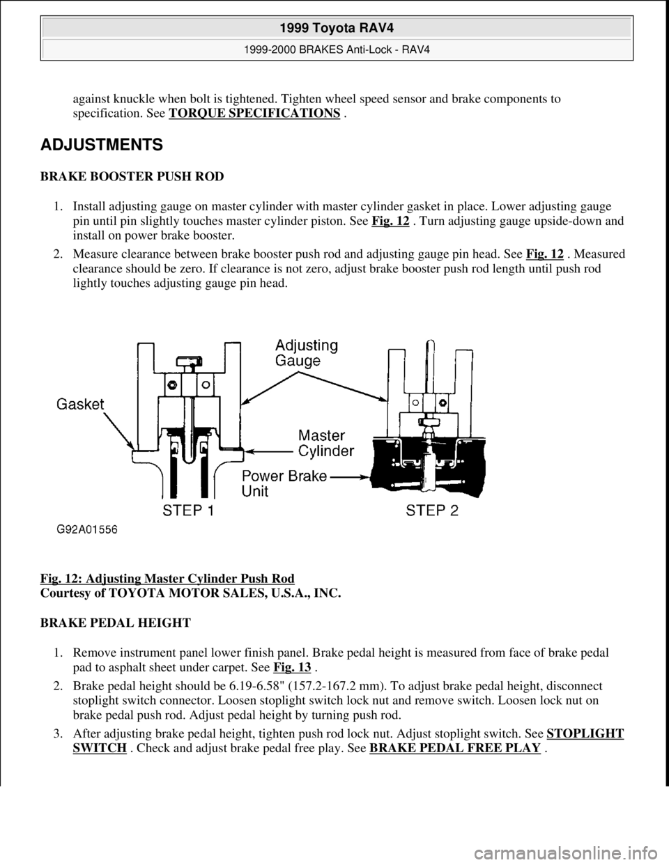
1. Install adjusting gauge on master cylinder with master cylinder gasket in place. Lower adjusting gauge
pin until pin slightly touches master cylinder piston. See Fig. 12
. Turn adjusting gauge upside-down and
install on power brake booster.
2. Measure clearance between brake booster push rod and adjusting gauge pin head. See Fig. 12
. Measured
clearance should be zero. If clearance is not zero, adjust brake booster push rod length until push rod
lightly touches adjusting gauge pin head.
Fig. 12: Adjusting Master Cylinder Push Rod
Courtesy of TOYOTA MOTOR SALES, U.S.A., INC.
BRAKE PEDAL HEIGHT
1. Remove instrument panel lower finish panel. Brake pedal height is measured from face of brake pedal
pad to asphalt sheet under carpet. See Fig. 13
.
2. Brake pedal height should be 6.19-6.58" (157.2-167.2 mm). To adjust brake pedal height, disconnect
stoplight switch connector. Loosen stoplight switch lock nut and remove switch. Loosen lock nut on
brake pedal push rod. Adjust pedal height by turning push rod.
3. After adjusting brake pedal height, tighten push rod lock nut. Adjust stoplight switch. See STOPLIGHT
SWITCH . Check and adjust brake pedal free play. See BRAKE PEDAL FREE PLAY.
1999 Toyota RAV4
1999-2000 BRAKES Anti-Lock - RAV4
Microsoft
Sunday, November 22, 2009 10:06:17 AMPage 30 © 2005 Mitchell Repair Information Company, LLC.
Page 31 of 1632
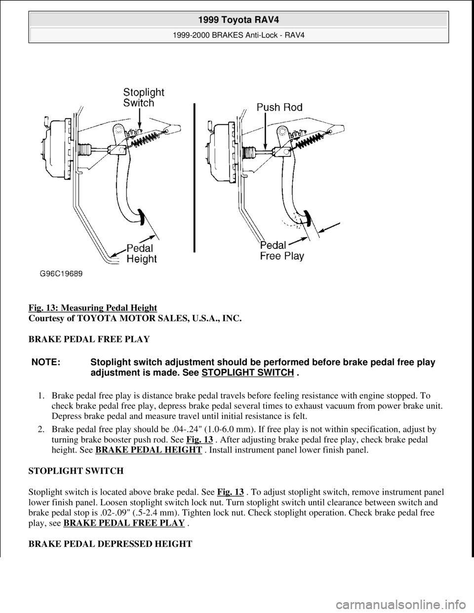
Fig. 13: Measuring Pedal Height
Courtesy of TOYOTA MOTOR SALES, U.S.A., INC.
BRAKE PEDAL FREE PLAY
1. Brake pedal free play is distance brake pedal travels before feeling resistance with engine stopped. To
check brake pedal free play, depress brake pedal several times to exhaust vacuum from power brake unit.
Depress brake pedal and measure travel until initial resistance is felt.
2. Brake pedal free play should be .04-.24" (1.0-6.0 mm). If free play is not within specification, adjust by
turning brake booster push rod. See Fig. 13
. After adjusting brake pedal free play, check brake pedal
height. See BRAKE PEDAL HEIGHT
. Install instrument panel lower finish panel.
STOPLIGHT SWITCH
Stoplight switch is located above brake pedal. See Fig. 13
. To adjust stoplight switch, remove instrument panel
lower finish panel. Loosen stoplight switch lock nut. Turn stoplight switch until clearance between switch and
brake pedal stop is .02-.09" (.5-2.4 mm). Tighten lock nut. Check stoplight operation. Check brake pedal free
play, see BRAKE PEDAL FREE PLAY .
BRAKE PEDAL DEPRESSED HEIGHT
NOTE: Stoplight switch adjustment should be performed before brake pedal free play
adjustment is made. See STOPLIGHT SWITCH
.
1999 Toyota RAV4
1999-2000 BRAKES Anti-Lock - RAV4
Microsoft
Sunday, November 22, 2009 10:06:17 AMPage 31 © 2005 Mitchell Repair Information Company, LLC.
Page 32 of 1632
Brake pedal depressed height is measured from face of brake pedal pad to asphalt sheet under carpet with
brakes applied. Measure brake pedal depressed height with engine running and weight of 110 lbs. (50 kg)
applied against brake pedal. Minimum brake pedal depressed height should be 2.95" (75.0 mm). If measured
distance is less than minimum height, inspect brake system.
TORQUE SPECIFICATIONS
TORQUE SPECIFICATIONS
WIRING DIAGRAMS
ApplicationFt. Lbs. (N.m)
Actuator Bracket Mounting Bolts14 (19)
Brakeline Fittings11 (15)
Hub Nut83 (110)
Push Rod Lock Nut18 (25)
Speed Sensor Harness-To-Rear Suspension Arm Bolts9 (13)
INCH Lbs. (N.m)
Actuator-To-Bracket Mounting Nuts48 (5.4)
Speed Sensor Harness-To-Body Bolts48 (5.4)
Wheel Speed Sensor Mounting Bolt71 (8)
1999 Toyota RAV4
1999-2000 BRAKES Anti-Lock - RAV4
Microsoft
Sunday, November 22, 2009 10:06:17 AMPage 32 © 2005 Mitchell Repair Information Company, LLC.
Page 203 of 1632
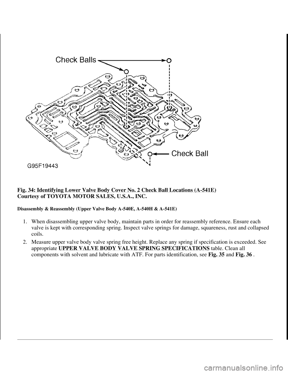
Fig. 34: Identifying Lower Valve Body Cover No. 2 Check Ball Locations (A-541E)
Courtesy of TOYOTA MOTOR SALES, U.S.A., INC.
Disassembly & Reassembly (Upper Valve Body A-540E, A-540H & A-541E)
1. When disassembling upper valve body, maintain parts in order for reassembly reference. Ensure each
valve is kept with corresponding spring. Inspect valve springs for damage, squareness, rust and collapsed
coils.
2. Measure upper valve body valve spring free height. Replace any spring if specification is exceeded. See
appropriate UPPER VALVE BODY VALVE SPRING SPECIFICATIONS
table. Clean all
components with solvent and lubricate with ATF. For parts identification, see Fig. 35
and Fig. 36.
1998 Toyota Avalon XLS
1997-99 AUTOMATIC TRANSMISSIONS Toyota A-540E, A-540H & A-541E Overhaul
Helpmelearn
November-03-08 10:28:18 AMPage 49 © 2005 Mitchell Repair Information Company, LLC.
Page 206 of 1632
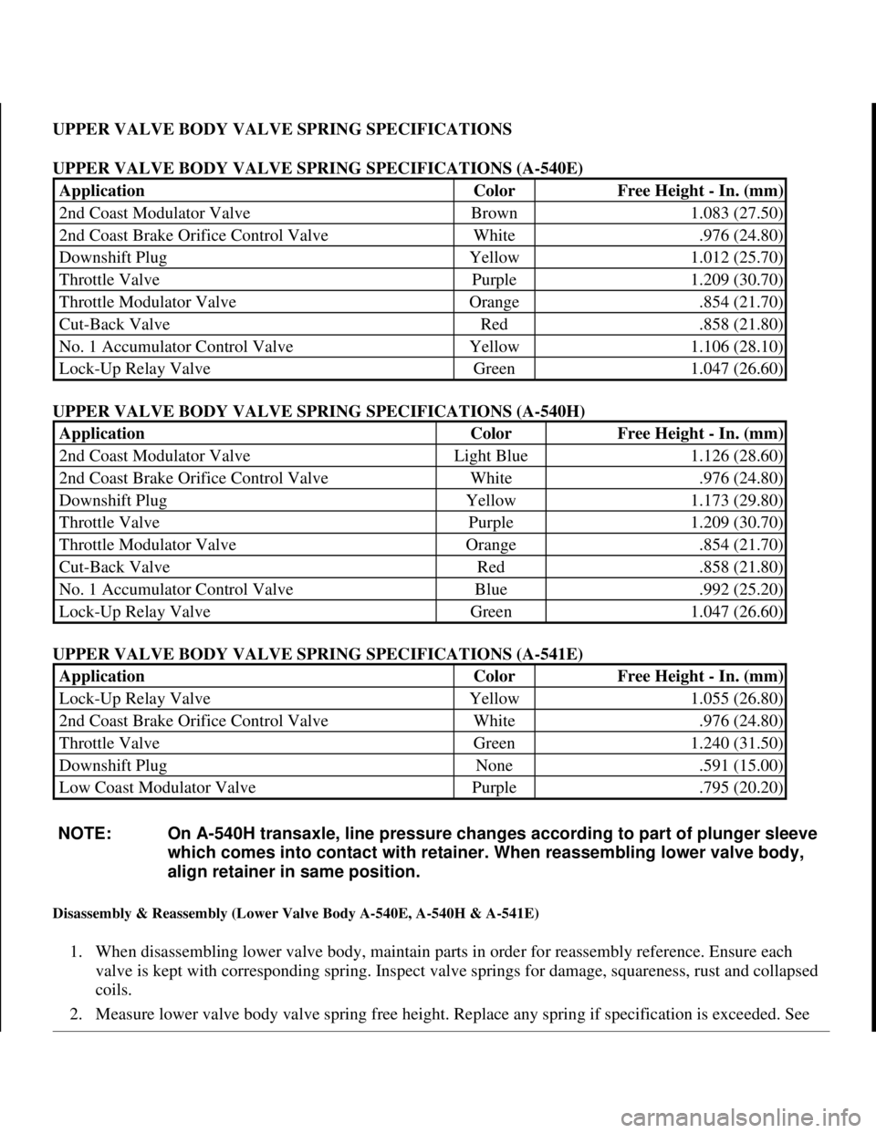
UPPER VALVE BODY VALVE SPRING SPECIFICATIONS
UPPER VALVE BODY VALVE SPRING SPECIFICATIONS (A-540E)
UPPER VALVE BODY VALVE SPRING SPECIFICATIONS (A-540H)
UPPER VALVE BODY VALVE SPRING SPECIFICATIONS (A-541E)
Disassembly & Reassembly (Lower Valve Body A-540E, A-540H & A-541E)
1. When disassembling lower valve body, maintain parts in order for reassembly reference. Ensure each
valve is kept with corresponding spring. Inspect valve springs for damage, squareness, rust and collapsed
coils.
2. Measure lower valve bod
y valve spring free height. Replace any spring if specification is exceeded. See
ApplicationColorFree Height - In. (mm)
2nd Coast Modulator ValveBrown1.083 (27.50)
2nd Coast Brake Orifice Control ValveWhite.976 (24.80)
Downshift PlugYellow1.012 (25.70)
Throttle ValvePurple1.209 (30.70)
Throttle Modulator ValveOrange.854 (21.70)
Cut-Back ValveRed.858 (21.80)
No. 1 Accumulator Control ValveYellow1.106 (28.10)
Lock-Up Relay ValveGreen1.047 (26.60)
ApplicationColorFree Height - In. (mm)
2nd Coast Modulator ValveLight Blue1.126 (28.60)
2nd Coast Brake Orifice Control ValveWhite.976 (24.80)
Downshift PlugYellow1.173 (29.80)
Throttle ValvePurple1.209 (30.70)
Throttle Modulator ValveOrange.854 (21.70)
Cut-Back ValveRed.858 (21.80)
No. 1 Accumulator Control ValveBlue.992 (25.20)
Lock-Up Relay ValveGreen1.047 (26.60)
ApplicationColorFree Height - In. (mm)
Lock-Up Relay ValveYellow1.055 (26.80)
2nd Coast Brake Orifice Control ValveWhite.976 (24.80)
Throttle ValveGreen1.240 (31.50)
Downshift PlugNone.591 (15.00)
Low Coast Modulator ValvePurple.795 (20.20)
NOTE: On A-540H transaxle, line pressure changes according to part of plunger sleeve
which comes into contact with retainer. When reassembling lower valve body,
align retainer in same position.
1998 Toyota Avalon XLS
1997-99 AUTOMATIC TRANSMISSIONS Toyota A-540E, A-540H & A-541E Overhaul
Helpmelearn
November-03-08 10:28:18 AMPage 52 © 2005 Mitchell Repair Information Company, LLC.
Page 207 of 1632
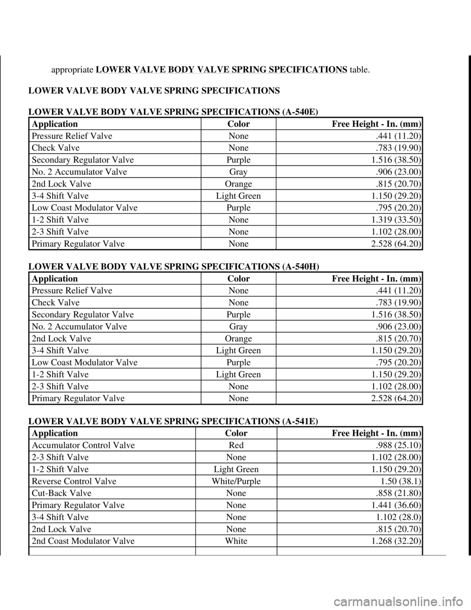
appropriate LOWER VALVE BODY VALVE SPRING SPECIFICATIONS table.
LOWER VALVE BODY VALVE SPRING SPECIFICATIONS
LOWER VALVE BODY VALVE SPRING SPECIFICATIONS (A-540E)
LOWER VALVE BODY VALVE SPRING SPECIFICATIONS (A-540H)
LOWER VALVE BODY VALVE SPRING SPECIFICATIONS (A-541E)
ApplicationColorFree Height - In. (mm)
Pressure Relief ValveNone.441 (11.20)
Check ValveNone.783 (19.90)
Secondary Regulator ValvePurple1.516 (38.50)
No. 2 Accumulator ValveGray.906 (23.00)
2nd Lock ValveOrange.815 (20.70)
3-4 Shift ValveLight Green1.150 (29.20)
Low Coast Modulator ValvePurple.795 (20.20)
1-2 Shift ValveNone1.319 (33.50)
2-3 Shift ValveNone1.102 (28.00)
Primary Regulator ValveNone2.528 (64.20)
ApplicationColorFree Height - In. (mm)
Pressure Relief ValveNone.441 (11.20)
Check ValveNone.783 (19.90)
Secondary Regulator ValvePurple1.516 (38.50)
No. 2 Accumulator ValveGray.906 (23.00)
2nd Lock ValveOrange.815 (20.70)
3-4 Shift ValveLight Green1.150 (29.20)
Low Coast Modulator ValvePurple.795 (20.20)
1-2 Shift ValveLight Green1.150 (29.20)
2-3 Shift ValveNone1.102 (28.00)
Primary Regulator ValveNone2.528 (64.20)
ApplicationColorFree Height - In. (mm)
Accumulator Control ValveRed.988 (25.10)
2-3 Shift ValveNone1.102 (28.00)
1-2 Shift ValveLight Green1.150 (29.20)
Reverse Control ValveWhite/Purple1.50 (38.1)
Cut-Back ValveNone.858 (21.80)
Primary Regulator ValveNone1.441 (36.60)
3-4 Shift ValveNone1.102 (28.0)
2nd Lock ValveNone.815 (20.70)
2nd Coast Modulator ValveWhite1.268 (32.20)
1998 Toyota Avalon XLS
1997-99 AUTOMATIC TRANSMISSIONS Toyota A-540E, A-540H & A-541E Overhaul
Helpmelearn
November-03-08 10:28:18 AMPage 53 © 2005 Mitchell Repair Information Company, LLC.
Page 341 of 1632
4. Refill brake fluid reservoir as necessary. Repeat step 3 until air is no longer discharged. On RAV4,
tighten front bleeder screw to 69 INCH lbs. (7.8 N.m), and tighten rear bleeder screw to 74 INCH lbs.
(8.3 N.m). On Sienna, tighten bleeder screw to 74 INCH lbs. (8.3 N.m). Tighten bleeder screw to 97
INCH lbs. (11 N.m) on Land Cruiser, Tacoma, Tundra & 4Runner. Ensure fluid leakage is not present.
Add fluid to reservoir. Repeat procedure for remaining wheels.
ADJUSTMENTS
BRAKE PEDAL HEIGHT
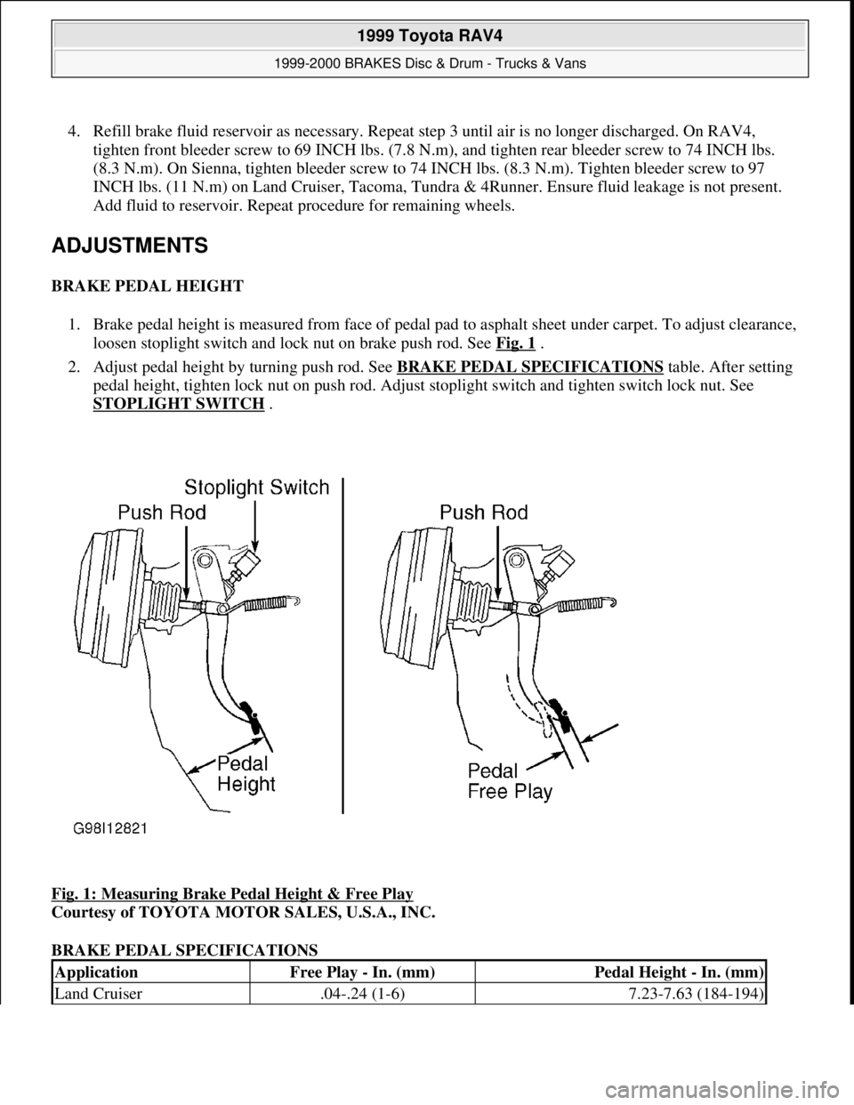
1. Brake pedal height is measured from face of pedal pad to asphalt sheet under carpet. To adjust clearance,
loosen stoplight switch and lock nut on brake push rod. See Fig. 1
.
2. Adjust pedal height by turning push rod. See BRAKE PEDAL SPECIFICATIONS
table. After setting
pedal height, tighten lock nut on push rod. Adjust stoplight switch and tighten switch lock nut. See
STOPLIGHT SWITCH
.
Fig. 1: Measuring Brake Pedal Height & Free Play
Courtesy of TOYOTA MOTOR SALES, U.S.A., INC.
BRAKE PEDAL SPECIFICATIONS
ApplicationFree Play - In. (mm)Pedal Height - In. (mm)
Land Cruiser.04-.24 (1-6)7.23-7.63 (184-194)
1999 Toyota RAV4
1999-2000 BRAKES Disc & Drum - Trucks & Vans
Microsoft
Sunday, November 22, 2009 10:07:28 AMPage 2 © 2005 Mitchell Repair Information Company, LLC.
Page 344 of 1632
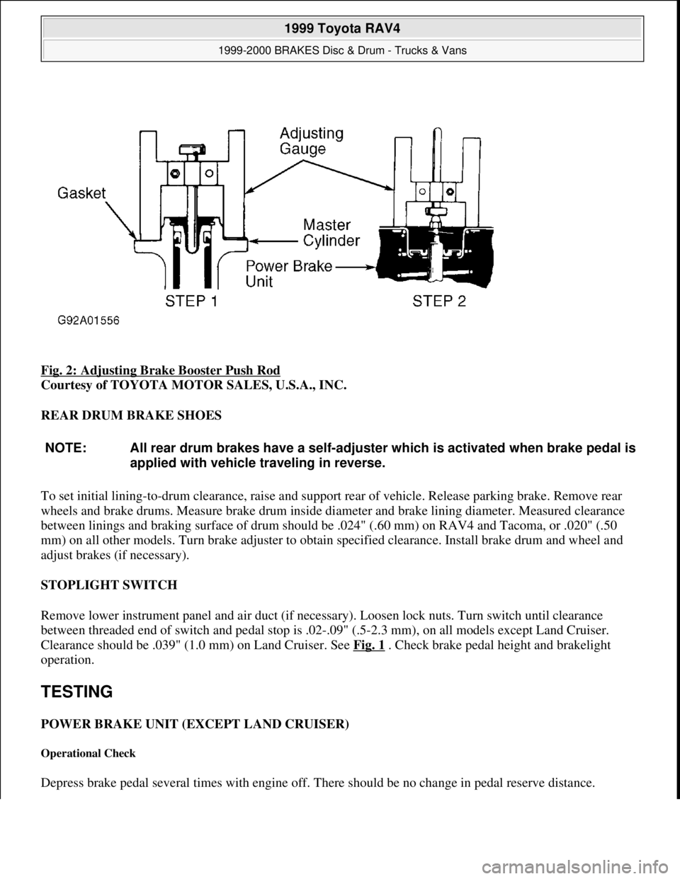
Fig. 2: Adjusting Brake Booster Push Rod
Courtesy of TOYOTA MOTOR SALES, U.S.A., INC.
REAR DRUM BRAKE SHOES
To set initial lining-to-drum clearance, raise and support rear of vehicle. Release parking brake. Remove rear
wheels and brake drums. Measure brake drum inside diameter and brake lining diameter. Measured clearance
between linings and braking surface of drum should be .024" (.60 mm) on RAV4 and Tacoma, or .020" (.50
mm) on all other models. Turn brake adjuster to obtain specified clearance. Install brake drum and wheel and
adjust brakes (if necessary).
STOPLIGHT SWITCH
Remove lower instrument panel and air duct (if necessary). Loosen lock nuts. Turn switch until clearance
between threaded end of switch and pedal stop is .02-.09" (.5-2.3 mm), on all models except Land Cruiser.
Clearance should be .039" (1.0 mm) on Land Cruiser. See Fig. 1
. Check brake pedal height and brakelight
operation.
TESTING
POWER BRAKE UNIT (EXCEPT LAND CRUISER)
Operational Check
Depress brake pedal several times with engine off. There should be no change in pedal reserve distance.
NOTE: All rear drum brakes have a self-adjuster which is activated when brake pedal is
applied with vehicle traveling in reverse.
1999 Toyota RAV4
1999-2000 BRAKES Disc & Drum - Trucks & Vans
Microsoft
Sunday, November 22, 2009 10:07:28 AMPage 5 © 2005 Mitchell Repair Information Company, LLC.
Page 345 of 1632
Depress brake pedal and start engine. If pedal goes down slightly, operation is normal.
Air Tightness Check
1. Start engine and run for 1-2 minutes, then turn engine off. Depress brake pedal several times slowly. If
pedal goes down farthest on first time, but gradually rises after second or third time, power brake unit is
airtight.
2. With engine stopped, depress brake pedal several times using normal pressure. Pedal should be low when
first depressed. On consecutive applications, pedal height should gradually rise. If pedal height does not
increase, check for air leaks.
LOAD-SENSING PROPORTIONING VALVE (LSPV) & BY-PASS VALVE (BPV)
Tacoma & Tundra
1. For testing purposes, rear axle is loaded to a specified weight. Set total rear axle weight to specified
amount. See LSPV REAR AXLE TEST WEIGHT
table.
2. Attach pressure gauge set to front caliper and rear wheel cylinder or caliper. Bleed air from system. See
BLEEDING BRAKE SYSTEM
. Depress brake pedal until front pressure is as specified. See LSPV
PRESSURE SPECIFICATIONS table. Wait 2 seconds and record rear pressure reading.
LSPV REAR AXLE TEST WEIGHT
LSPV PRESSURE SPECIFICATIONS NOTE: DO NOT depress brake pedal more than once or release pedal while
setting pressure on front gauge.
ApplicationLbs. (kg)
Tacoma
2WD1543 (700)
4WD1874 (850)
Tundra
V6
Engine
(5UZ-
FE)2205 (1000)
V8
Engine
(2UZ-
FE)2315 (1050)
4Runner2033 (922)
Application
Front Pressure - psi
(kg/cm
2 )
Rear Pressure - psi
(kg/cm
2 )
Tacoma
1999 Toyota RAV4
1999-2000 BRAKES Disc & Drum - Trucks & Vans
Microsoft
Sunday, November 22, 2009 10:07:28 AMPage 6 © 2005 Mitchell Repair Information Company, LLC.