hood release TOYOTA RAV4 1996 Service Repair Manual
[x] Cancel search | Manufacturer: TOYOTA, Model Year: 1996, Model line: RAV4, Model: TOYOTA RAV4 1996Pages: 1632, PDF Size: 41.64 MB
Page 80 of 1632
INSTRUMENT PANEL
Removal & Installation
1. Before proceeding, see SERVICE PRECAUTIONS . Turn ignition switch to LOCK position.
Disconnect negative battery cable. Wait at least 90 seconds.
2. Access and disconnect right and left seat belt pretensioner connectors. See SEAT BELT
PRETENSIONERS . Remove front door scuff plates and cowl side trim boards. See Fig. 13 . Remove
steering wheel. See STEERING WHEEL
. Remove steering column covers and cluster finish panel.
Remove instrument cluster. Remove hood lock release lever.
3. Remove lower finish panel and instrument panel lower insert. Remove No. 2 heater-to-register duct.
Remove steering column assembly. See STEERING COLUMN
. Remove 2 screws and center cluster
finish panel. Pull off heater control knobs and pry off heater control name plate. Pry off cluster instrument
panel, then remove 3 screws from heater control assembly. Disconnect connectors and remove cluster
instrument panel.
4. Disconnect control cables and remove heater control assembly. Remove radio assembly. Remove console
box. Tape tip of screwdriver and remove lower center cluster finish panel. Disconnect connectors.
Remove stereo opening cover. Remove glove box assembly. Remove side trim cover. Disconnect
remaining connectors and remove bolts, then remove instrument panel.
5. To install, reverse removal procedure. Tighten fasteners to specification. See TORQUE
SPECIFICATIONS . Check AIR BAG warning light to ensure system is functioning properly. See
SYSTEM OPERATION CHECK
.
1999 Toyota RAV4
AIR BAG RESTRAINT SYSTEM 1999 Toyota
Microsoft
Sunday, November 22, 2009 10:33:22 AMPage 17 © 2005 Mitchell Repair Information Company, LLC.
Page 692 of 1632
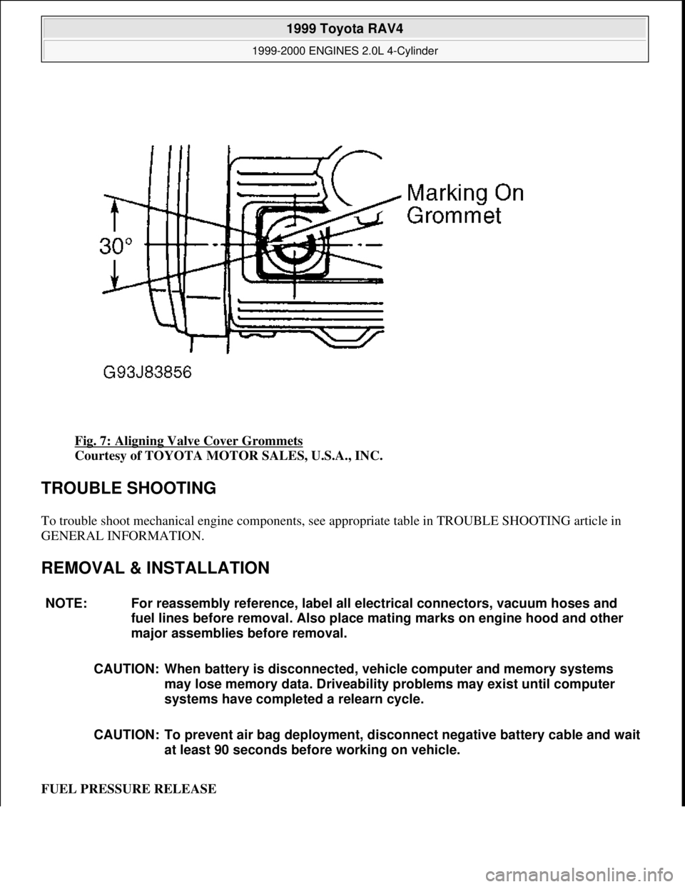
Fig. 7: Aligning Valve Cover Grommets
Courtesy of TOYOTA MOTOR SALES, U.S.A., INC.
TROUBLE SHOOTING
To trouble shoot mechanical engine components, see appropriate table in TROUBLE SHOOTING article in
GENERAL INFORMATION.
REMOVAL & INSTALLATION
FUEL PRESSURE RELEASE
NOTE: For reassembly reference, label all electrical connectors, vacuum hoses and
fuel lines before removal. Also place mating marks on engine hood and other
major assemblies before removal.
CAUTION: When battery is disconnected, vehicle computer and memory systems
may lose memory data. Driveability problems may exist until computer
systems have completed a relearn cycle.
CAUTION: To prevent air bag deployment, disconnect negative battery cable and wait
at least 90 seconds before working on vehicle.
1999 Toyota RAV4
1999-2000 ENGINES 2.0L 4-Cylinder
Microsoft
Sunday, November 22, 2009 10:22:26 AMPage 9 © 2005 Mitchell Repair Information Company, LLC.
Page 693 of 1632
1. Remove driver-side rear seat and floor panel cover for access to fuel pump electrical connector.
2. Disconnect fuel pump electrical connector. Start engine and allow engine to idle until engine stalls. Turn
ignition off.
3. Reconnect fuel pump electrical connector. Reinstall floor panel cover and driver-side rear seat.
4. Disconnect negative battery cable. Place an approved gasoline container under fuel line. Cover fuel line
connection with shop towel.
5. Slowly loosen fuel line connection to release fuel pressure. Once fuel pressure is released, fuel system
components may be serviced.
ENGINE
Removal
1. Engine and transaxle are removed as an assembly from bottom of engine compartment. Release fuel
pressure. See FUEL PRESSURE RELEASE
. Remove hood, battery and battery tray. Drain cooling
system, and engine and transaxle oil.
2. Disconnect control cables at throttle body. Remove air cleaner assembly and air cleaner case. Remove
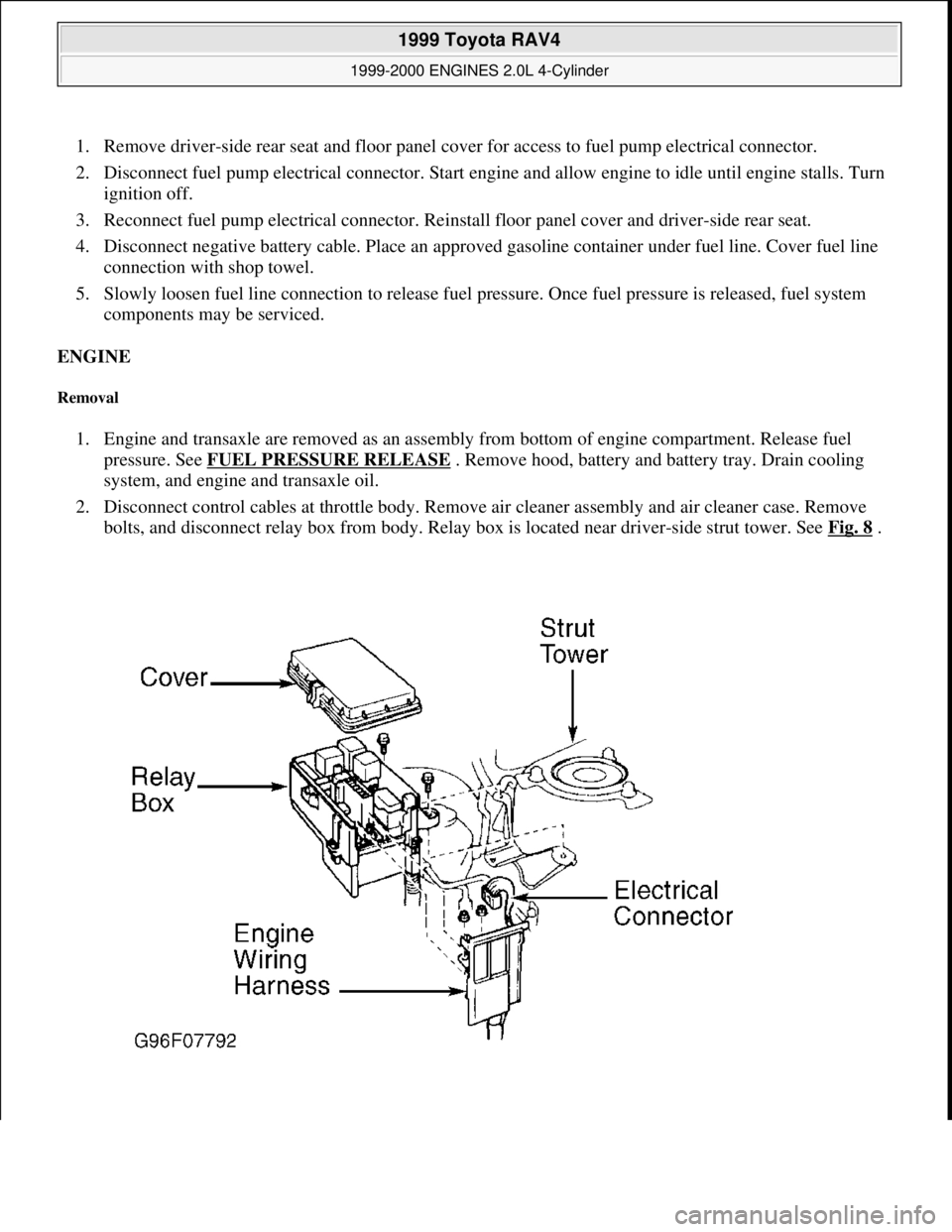
bolts, and disconnect relay box from body. Relay box is located near driver-side strut tower. See Fig. 8
.
1999 Toyota RAV4
1999-2000 ENGINES 2.0L 4-Cylinder
Microsoft
Sunday, November 22, 2009 10:22:26 AMPage 10 © 2005 Mitchell Repair Information Company, LLC.
Page 758 of 1632
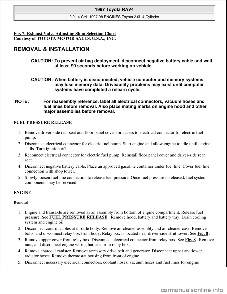
Fig. 7: Exhaust Valve Adjusting Shim Selection Chart
Courtesy of TOYOTA MOTOR SALES, U.S.A., INC.
REMOVAL & INSTALLATION
FUEL PRESSURE RELEASE
1. Remove driver-side rear seat and floor panel cover for access to electrical connector for electric fuel
pump.
2. Disconnect electrical connector for electric fuel pump. Start engine and allow engine to idle until engine
stalls. Turn ignition off.
3. Reconnect electrical connector for electric fuel pump. Reinstall floor panel cover and driver-side rear
seat.
4. Disconnect negative battery cable. Place an approved gasoline container under fuel line. Cover fuel line
connection with shop towel.
5. Slowly loosen fuel line connection to release fuel pressure. Once fuel pressure is released, fuel system
components may be serviced.
ENGINE
Removal
1. Engine and transaxle are removed as an assembly from bottom of engine compartment. Release fuel
pressure. See FUEL PRESSURE RELEASE
. Remove hood, battery and battery tray. Drain cooling
system and engine oil.
2. Disconnect control cables at throttle body. Remove air cleaner assembly and air cleaner case. Remove
bolts, and disconnect relay box from body. Relay box is located near driver-side strut tower. See Fig. 8
.
3. Remove upper cover from relay box. Disconnect electrical connector from relay box. See Fig. 8
. Remove
nuts, and disconnect engine wiring harness from relay box.
4. Remove charcoal canister. Remove accessory drive belt and generator. Disconnect upper and lower
radiator hoses. Remove thermostat housing from front of engine.
5. Disconnect necessar
y electrical connectors, coolant hoses, vacuum hoses and fuel lines for engine CAUTION: To prevent air bag deployment, disconnect negative battery cable and wait
at least 90 seconds before working on vehicle.
CAUTION: When battery is disconnected, vehicle computer and memory systems
may lose memory data. Driveability problems may exist until computer
systems have completed a relearn cycle.
NOTE: For reassembly reference, label all electrical connectors, vacuum hoses and
fuel lines before removal. Also place mating marks on engine hood and other
major assemblies before removal.
1997 Toyota RAV4
2.0L 4-CYL 1997-98 ENGINES Toyota 2.0L 4-Cylinder
Microsoft
Sunday, November 22, 2009 10:23:30 AMPage 10 © 2005 Mitchell Repair Information Company, LLC.
Page 864 of 1632
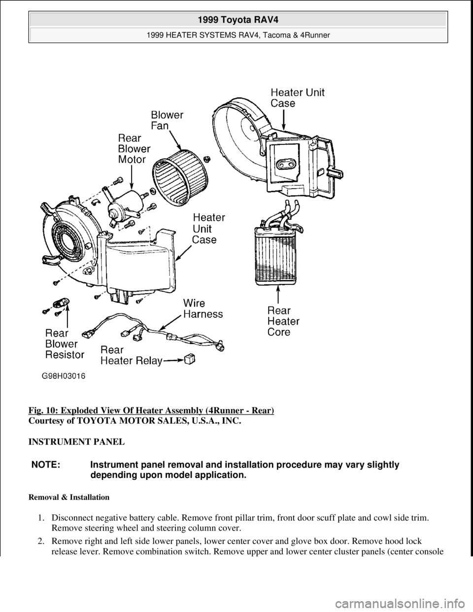
Fig. 10: Exploded View Of Heater Assembly (4Runner - Rear)
Courtesy of TOYOTA MOTOR SALES, U.S.A., INC.
INSTRUMENT PANEL
Removal & Installation
1. Disconnect negative battery cable. Remove front pillar trim, front door scuff plate and cowl side trim.
Remove steering wheel and steering column cover.
2. Remove right and left side lower panels, lower center cover and glove box door. Remove hood lock
release lever. Remove combination switch. Remove upper and lower center cluster panels (center console
NOTE: Instrument panel removal and installation procedure may vary slightly
depending upon model application.
1999 Toyota RAV4
1999 HEATER SYSTEMS RAV4, Tacoma & 4Runner
Microsoft
Sunday, November 22, 2009 10:30:50 AMPage 14 © 2005 Mitchell Repair Information Company, LLC.
Page 924 of 1632
Disconnect washer level warning switch connector. Check for continuity between washer level warning switch
connector terminals. With washer level warning switch off (float up), no continuity should exist. With washer
level warning switch on (float off), continuity should exist. If continuity is not as specified, replace washer level
warning switch.
REMOVAL & INSTALLATION
INSTRUMENT CLUSTER
Removal & Installation (Land Cruiser)
1. Disable air bag system, remove driver's air bag and steering wheel. See AIR BAG RESTRAINT
SYSTEMS article. Remove steering column covers. Remove hood release and fuel door levers. Remove
screws from instrument panel lower finish panel and remove panel.
2. Remove instrument cluster finish panel. Remove retaining screws from instrument cluster. Pull cluster
outward enough to disconnect wiring harness connectors. Remove instrument cluster. To install, reverse
removal procedure.
Removal & Installation (RAV4)
1. Disable air bag system, remove driver's air bag and steering wheel. See AIR BAG RESTRAINT
SYSTEMS article. Remove steering column covers. Remove instrument cluster finish panel.
2. Remove 4 instrument cluster retaining screws. Pull cluster outward far enough to disconnect wiring
harness connectors. Remove instrument cluster. To install, reverse removal procedure.
Removal & Installation (Sienna)
1. Disable air bag system, driver's air bag and steering wheel. See AIR BAG RESTRAINT SYSTEMS
article. Remove steering column covers. Remove hood release lever. Remove lower finish panel and
safety pad insert. See Fig. 22
.
2. Using flat-blade screwdriver, pry center cluster finish panel loose from 4 retaining clips and remove
panel. Remove ashtray. Remove lower center cluster finish panel. Remove instrument cluster finish
panel. Remove clock, No. 1 register and No. 2 register from instrument cluster finish panel. Remove
retaining screws from instrument cluster.
3. Pull cluster outward enough to disconnect wiring harness connectors. Remove instrument cluster. To
install, reverse removal procedure. WARNING:Deactivate air bag system before performing any service operation. See
AIR BAG RESTRAINT SYSTEMS article. DO NOT apply electrical power to
any component on steering column without first deactivating air bag
system. Air bag may deploy.
1999 Toyota RAV4
1999-2000 ACCESSORIES & EQUIPMENT Instrument Panels - Trucks
Microsoft
Sunday, November 22, 2009 10:54:10 AMPage 34 © 2005 Mitchell Repair Information Company, LLC.
Page 926 of 1632
Fig. 22: Removing Instrument Panel (Sienna)
Courtesy of TOYOTA MOTOR SALES, U.S.A., INC.
Removal & Installation (Tacoma)
1. Disable air bag system, remove driver's air bag and steering wheel. See AIR BAG RESTRAINT
SYSTEMS article. Remove lower finish panel. Remove steering column covers.
2. Remove starter switch bezel (if necessary). Remove cluster finish panel retaining screws. Using flat-
blade
screwdriver, pry instrument cluster finish panel loose from 3 retaining clips.
3. Remove 4 instrument cluster retaining screws. Pull instrument cluster out far enough to disconnect wiring
harness connectors. Remove instrument cluster. To install, reverse removal procedure.
Removal & Installation (Tundra)
Disable air bag system, remove driver's air bag and steering wheel. See AIR BAG RESTRAINT SYSTEMS
article. Remove steering column covers and combination switch. Remove combination meter finish panel.
Remove combination meter. To install, reverse removal procedure.
Removal & Installation (4Runner)
1. Disable air bag system, remove driver's air bag and steering wheel. See AIR BAG RESTRAINT
SYSTEMS article. Remove steering column covers. Remove 4 lower finish panel retaining bolts. Remove
hood release and fuel tank lid release lever.
2. Using a screwdriver, carefully remove instrument panel lower finish panel. Remove ignition switch bezel.
Disconnect air registers. Remove 4 retaining screws from instrument cluster finish panel. Carefully
remove cluster finish panel. Disconnect wiring harness connectors.
3. Remove instrument cluster retaining screws. Pull cluster outward enough to disconnect wiring harness
connectors. Remove instrument cluster. To install, reverse removal procedure.
WIRING DIAGRAMS
1999 Toyota RAV4
1999-2000 ACCESSORIES & EQUIPMENT Instrument Panels - Trucks
Microsoft
Sunday, November 22, 2009 10:54:10 AMPage 36 © 2005 Mitchell Repair Information Company, LLC.
Page 1213 of 1632
1. Disconnect and shield negative battery cable. Remove steering wheel pad. Remove steering wheel. See
STEERING WHEEL & AIR BAG
.
2. Remove upper and lower steering column covers. Disconnect connectors. Remove 4 screws and air bag
spiral and combination switch.
3. Remove instrument cluster lower finish panel. Remove fuse box opening cover. Remove 2 screws, and
disconnect hood release handle. Remove 5 retaining screws and instrument panel lower finish panel.
4. Remove remaining instrument cluster panel (4 bolts). Remove air duct from instrument panel outlet.
5. Loosen lower clamp bolt "A" from intermediate-to-steering gear "U" joint. Remove upper intermediate
shaft clamp bolt "B". See Fig. 3
. Place match marks on steering gear shaft and "U" joint. Fully remove
lower clamp bolt "A". Remove intermediate shaft.
6. To install, reverse removal procedure. Tighten all bolts to specifications. See TORQUE
SPECIFICATIONS . Ensure spiral cable is properly installed and adjusted. See SPIRAL CABLEunder
ADJUSTMENTS.
1999 Toyota RAV4
1999-2000 STEERING Steering Columns - Standard
Microsoft
Sunday, November 22, 2009 10:34:51 AMPage 6 © 2005 Mitchell Repair Information Company, LLC.
Page 1215 of 1632
1. Disconnect and shield negative battery cable. Remove steering wheel. See STEERING WHEEL & AIR
BAG .
2. Remove front door scuff plate and cowl side trim. Remove instrument cluster lower finish panel after
disconnecting hood release handle. Remove lower instrument panel insert.
3. Remove upper and lower steering column covers. Disconnect connectors. Remove 3 screws and air bag
spiral and combination switch.
4. Remove air duct from instrument panel outlet. Remove steering column floor hole cover (5 bolts).
5. Place match marks on steering gear shaft and "U" joint. Loosen upper "U" joint clamp bolt, and fully
remove lower "U" joint clamp bolt. Disconnect steering column assembly connectors. Remove 2 steering
column mounting bolts and nuts. Remove steering column from instrument panel.
6. Fully remove upper "U" joint clamp bolt. Remove "U" joint assembly.
7. To install, reverse removal procedure. Tighten all bolts to specifications. See TORQUE
SPECIFICATIONS . Ensure spiral cable is properly installed and adjusted. See SPIRAL CABLEunder
ADJUSTMENTS.
Removal & Installation (RAV4)
1. Disconnect and shield negative battery cable. Remove steering wheel. See STEERING WHEEL & AIR
BAG .
2. Remove lower instrument finish panel after disconnecting hood release handle. Remove lower instrument
panel insert.
3. Remove upper and lower steering column covers. Disconnect 2 electrical connectors and air bag
connector. Remove 3 screws and air bag spiral and combination switch. Remove air duct from instrument
panel outlet.
4. Place match marks on steering gear shaft and intermediate shaft across clamp. Loosen lower "U" joint
clamp bolt. Fully remove clamp bolt at steering gear connection.
5. Disconnect steering column assembly connectors. Loosen hole cover clamp bolt. Remove 2 steering
column mounting bolts and nuts. Remove steering column from instrument panel.
6. Remove floor hole cover. Fully remove upper "U" joint clamp bolt. Remove "U" joint assembly.
7. To install, reverse removal procedure. Tighten all bolts to specifications. See TORQUE
SPECIFICATIONS . Ensure spiral cable is properly installed and adjusted. See SPIRAL CABLEunder
ADJUSTMENTS.
Removal & Installation (Tacoma)
1. Disconnect and shield negative battery cable. Remove steering wheel. See STEERING WHEEL & AIR
BAG .
2. Remove upper and lower steering column covers. Disconnect hood release handle from instrument panel.
Remove 4 bolts and 1 screw. Remove instrument panel lower left finish panel. Remove air duct from
instrument panel outlet.
3. Disconnect 3 electrical connectors. Disconnect air bag connector. Remove 3 screws and combination
switch with spiral cable. Remove 2 bolts, and disconnect Junction Block No. 1.
4. On models with column shift, remove pin and clip, and disconnect cable assembly from steering column
1999 Toyota RAV4
1999-2000 STEERING Steering Columns - Standard
Microsoft
Sunday, November 22, 2009 10:34:51 AMPage 8 © 2005 Mitchell Repair Information Company, LLC.
Page 1216 of 1632
shift lever assembly.
5. If equipped with 2WD, place match marks across intermediate shaft and steering gear shaft. Loosen
clamp bolt just above floorboard. Remove lower "U" joint bolt at steering gear shaft connection.
Disconnect intermediate shaft. Fully remove bolt above floorboard, and remove intermediate shaft.
Remove steering column hole cover.
6. If equipped with 4WD, place match marks across intermediate shaft to steering gear housing. Loosen
upper clamp bolt (above yoke), and fully remove clamp bolt at connection to steering gear. Disconnect
intermediate shaft. Fully remove upper clamp bolt, and remove intermediate shaft. Remove steering
column floor hole cover.
7. On all models, disconnect column electrical connectors. Remove 2 steering column retaining bolts and
nuts. Remove steering column.
8. If equipped with 2WD, place match marks across column sliding yoke "U" joint connections. Remove
sliding yoke.
9. If equipped with 4WD, place match marks across column "U" joint connections above floor hole cover.
Remove upper clamp bolt. Remove "U" joint. Remove floor hole cover.
10. To install, reverse removal procedure. Tighten all bolts to specifications. See TORQUE
SPECIFICATIONS . Ensure spiral cable is properly installed and adjusted. See SPIRAL CABLEunder
ADJUSTMENTS.
Removal (Tundra)
1. Disconnect and shield negative battery cable. Remove steering wheel. See STEERING WHEEL & AIR
BAG .
2. Remove 3 screws and upper and lower steering column covers. Disconnect electrical connectors and air
bag connector. Remove 3 screws and air bag spiral and combination switch with spiral cable.
3. Remove instrument lower finish panel. Remove 2 screws, and disconnect hood release lever from panel.
Remove 4 bolts and instrument panel lower finish panel.
4. Remove No. 2 heater-to-register duct and brake pedal return spring.
5. Place match marks on No. 2 "U" joint and No. 2 intermediate shaft assembly. See Fig. 3
. Remove bolt
"A". Place match marks on No. 2 intermediate shaft assembly and control valve shaft. Remove bolt "B".
Remove No. 2 intermediate shaft assembly. Remove 3 bolts and column hole cover No. 2.
6. On models equipped with A/T, disconnect cable assembly from column shift lever assembly. Disconnect
connectors. Remove 4 steering column set nuts. Pull out steering column assembly with No. 2 "U" joint
assembly.
7. Place match marks on steering column assembly and No. 2 "U" joint assembly. Remove bolt and column
hole cover No. 2. Disconnect No. 2 "U" joint assembly.
Installation
1. Insert column hole cover No. 2. Align match marks on column assembly and No. 2 "U" joint assembly.
Install bolt to connect No. 2 "U" joint assembly.
2. Install column assembly with No. 2 "U" joint assembly. Install 4 steering column set nuts. Connect
connectors. On models equipped with A/T, connect transmission control cable assembly to shift lever
assembly.
1999 Toyota RAV4
1999-2000 STEERING Steering Columns - Standard
Microsoft
Sunday, November 22, 2009 10:34:51 AMPage 9 © 2005 Mitchell Repair Information Company, LLC.