jump start terminals TOYOTA RAV4 1996 Service Repair Manual
[x] Cancel search | Manufacturer: TOYOTA, Model Year: 1996, Model line: RAV4, Model: TOYOTA RAV4 1996Pages: 1632, PDF Size: 41.64 MB
Page 3 of 1632
If cause of faulty operation cannot be located with basic diagnosis, ABS electronic control system must be
checked. See DIAGNOSIS & TESTING
.
When ignition is turned on, ABS warning light should come on, then go out after 3 seconds. If ABS warning
light does not operate as specified, go to ABS WARNING LIGHT under DIAGNOSIS & TESTING
.
DIAGNOSIS & TESTING
RETRIEVING DIAGNOSTIC TROUBLE CODES
ABS Warning Light Diagnostics
1. Ensure battery voltage is 12 volts. Turn ignition switch to ON position. ABS warning light should
illuminate, then go out after 3 seconds. If ABS warning light does not illuminate, check fuse, bulb, and
wiring harness. See ABS WARNING LIGHT
.
2. Remove short pin from DLC1. DLC1 is located in engine compartment, on left side of engine. See Fig.
2 . Using a jumper wire, jumper DLC1 terminals Tc and E1 . If a malfunction is detected, ABS warning
light will begin to flash a 2-digit Diagnostic Trouble Code (DTC). First number of blinks will equal first
digit in DTC. After a 1.5-second pause, second number of blinks will equal second digit in DTC.
3. If 2 or more DTCs are stored, there will be a 2.5-second pause between each DTC. After all DTCs are
flashed, there will be a 4 second pause and all DTCs will repeat. If ABS system is functioning properly,
ABS warning light will blink 2 times per second. For code definitions, see DTC DEFINITIONS
. For
DTC diagnosis, see DIAGNOSTIC TESTS
.
4. After replacing or repairing components, clear DTCs. If battery cables were disconnected during repairs,
all DTCs will be erased. If battery cables were not disconnected during repairs, see CLEARING DTCS
.
DTC DEFINITIONS NOTE: DO NOT start engine when retrieving DTCs.
NOTE: Speed sensor diagnostics and code retrieval use different DLC1 terminals to
access DTCs. If a speed sensor or speed sensor circuit problem is suspected,
see SPEED SENSOR DIAGNOSTICS
.
DTCCircuit/Malfunction
ABS-Related DTCs (1)
11 Open In ABS Solenoid Relay Circuit
12 Short In ABS Solenoid Relay Circuit
13 Open In ABS Pump Motor Relay Circuit
14 Short In ABS Pump Motor Relay Circuit
21 Open/Shorted RF Solenoid, Defective ABS
Actuator
22 Open/Shorted LF Solenoid, Defective ABS
Actuator
1999 Toyota RAV4
1999-2000 BRAKES Anti-Lock - RAV4
Microsoft
Sunday, November 22, 2009 10:06:17 AMPage 3 © 2005 Mitchell Repair Information Company, LLC.
Page 5 of 1632
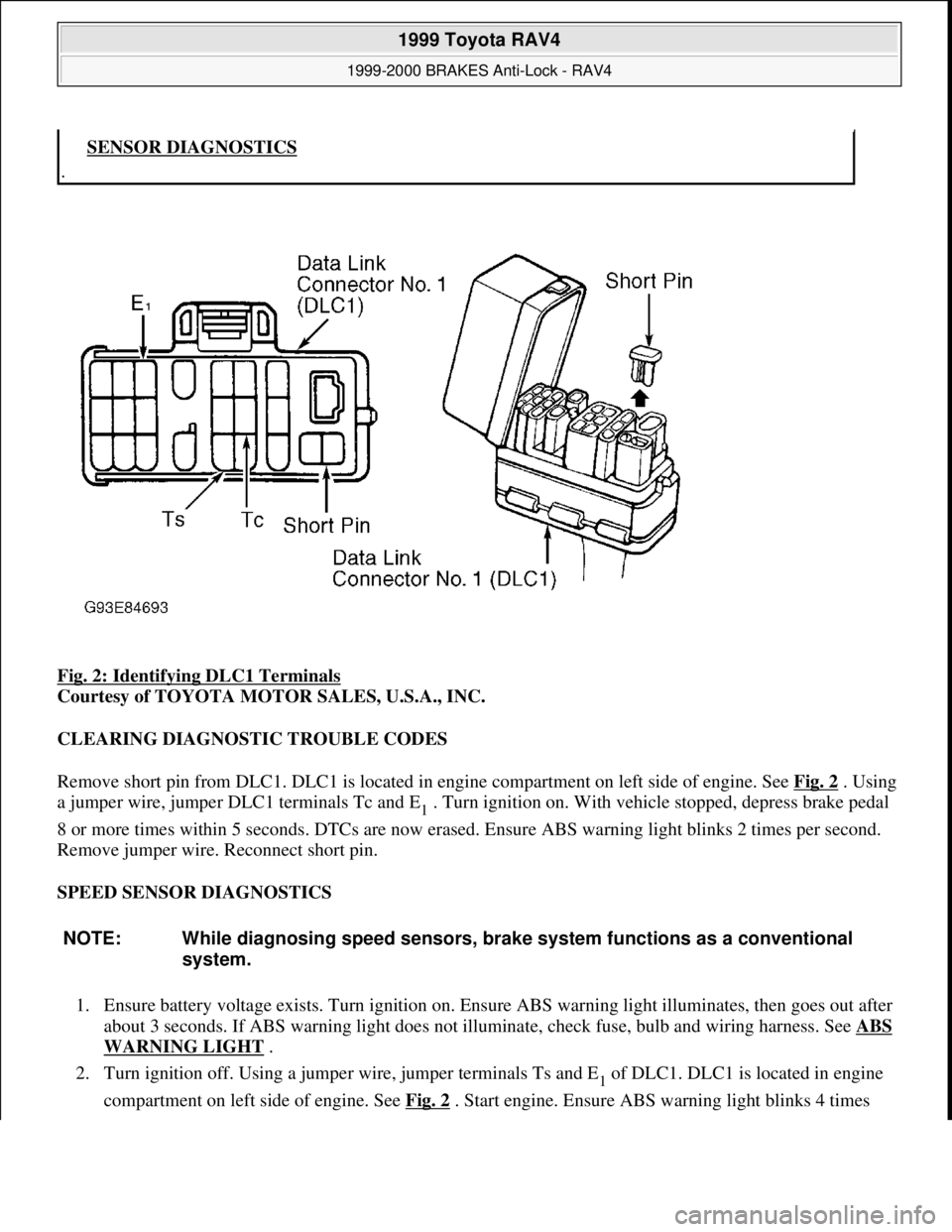
Fig. 2: Identifying DLC1 Terminals
Courtesy of TOYOTA MOTOR SALES, U.S.A., INC.
CLEARING DIAGNOSTIC TROUBLE CODES
Remove short pin from DLC1. DLC1 is located in engine compartment on left side of engine. See Fig. 2
. Using
a jumper wire, jumper DLC1 terminals Tc and E
1 . Turn ignition on. With vehicle stopped, depress brake pedal
8 or more times within 5 seconds. DTCs are now erased. Ensure ABS warning light blinks 2 times per second.
Remove jumper wire. Reconnect short pin.
SPEED SENSOR DIAGNOSTICS
1. Ensure battery voltage exists. Turn ignition on. Ensure ABS warning light illuminates, then goes out after
about 3 seconds. If ABS warning light does not illuminate, check fuse, bulb and wiring harness. See ABS
WARNING LIGHT .
2. Turn ignition off. Using a jumper wire, jumper terminals Ts and E
1 of DLC1. DLC1 is located in engine
compartment on left side of en
gine. See Fig. 2. Start engine. Ensure ABS warning light blinks 4 times
.SENSOR DIAGNOSTICS
NOTE: While diagnosing speed sensors, brake system functions as a conventional
system.
1999 Toyota RAV4
1999-2000 BRAKES Anti-Lock - RAV4
Microsoft
Sunday, November 22, 2009 10:06:17 AMPage 5 © 2005 Mitchell Repair Information Company, LLC.
Page 51 of 1632
CLEARING CODES
1. At DLC, connect a jumper wire to terminal Tc, and another jumper wire to terminal AB. See Fig. 12
.
Turn ignition switch to ACC or ON position. Wait about 6 seconds.
2. Starting with terminal Tc, apply body ground alternately to terminal Tc and terminal AB twice each, in
cycles of 1/2 to 1 1/2 seconds. Finally, keep applying body ground to terminal Tc until air bag warning
light flashes quickly, indicating codes are cleared.
DIAGNOSIS
AIR BAG WARNING LIGHT DOES NOT COME ON AT ALL
11Short To Ground In Squib Circuit
12Short To Battery In Squib Circuit
14Open In D Squib Circuit
31Air Bag Sensor Assembly Malfunction
54Open In P Squib Circuit
NOTE: When alternately connecting jumper probes to terminals, simultaneously
release one probe from one terminal while connecting other probe to other
terminal. If time interval between probings is too long, codes will not clear.
WARNING:Failure to follow air bag service precautions may result in air bag
deployment and personal injury. See SERVICE PRECAUTIONS
. After
component replacement, perform system operational check to ensure
proper system operation. See SYSTEM OPERATION CHECK
.
CAUTION: Ensure ignition switch is in LOCK position before disconnecting or
connecting negative battery cable. If ignition switch is in ACC or ON
position when negative battery cable is disconnected or connected, center
air bag sensor may be damaged.
NOTE: For air bag sensor connector terminal identification, see Fig. 13
.
1996 Toyota 4Runner
AIR BAG RESTRAINT SYSTEM 1996 ACCESSORIES/SAFETY EQUIPMENT Toyota Air Bag Restraint System
Microsoft
Tuesday, August 18, 2009 7:33:32 PMPage 17 © 2005 Mitchell Repair Information Company, LLC.
Page 85 of 1632
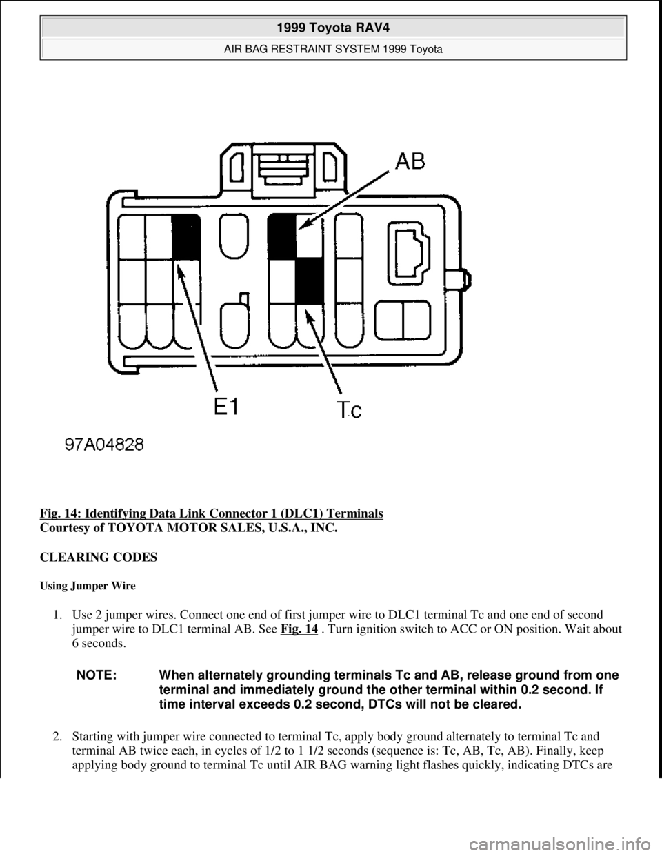
Fig. 14: Identifying Data Link Connector 1 (DLC1) Terminals
Courtesy of TOYOTA MOTOR SALES, U.S.A., INC.
CLEARING CODES
Using Jumper Wire
1. Use 2 jumper wires. Connect one end of first jumper wire to DLC1 terminal Tc and one end of second
jumper wire to DLC1 terminal AB. See Fig. 14
. Turn ignition switch to ACC or ON position. Wait about
6 seconds.
2. Starting with jumper wire connected to terminal Tc, apply body ground alternately to terminal Tc and
terminal AB twice each, in cycles of 1/2 to 1 1/2 seconds (sequence is: Tc, AB, Tc, AB). Finally, keep
appl
ying body ground to terminal Tc until AIR BAG warning light flashes quickly, indicating DTCs are
NOTE: When alternately grounding terminals Tc and AB, release ground from one
terminal and immediately ground the other terminal within 0.2 second. If
time interval exceeds 0.2 second, DTCs will not be cleared.
1999 Toyota RAV4
AIR BAG RESTRAINT SYSTEM 1999 Toyota
Microsoft
Sunday, November 22, 2009 10:33:23 AMPage 22 © 2005 Mitchell Repair Information Company, LLC.
Page 1071 of 1632
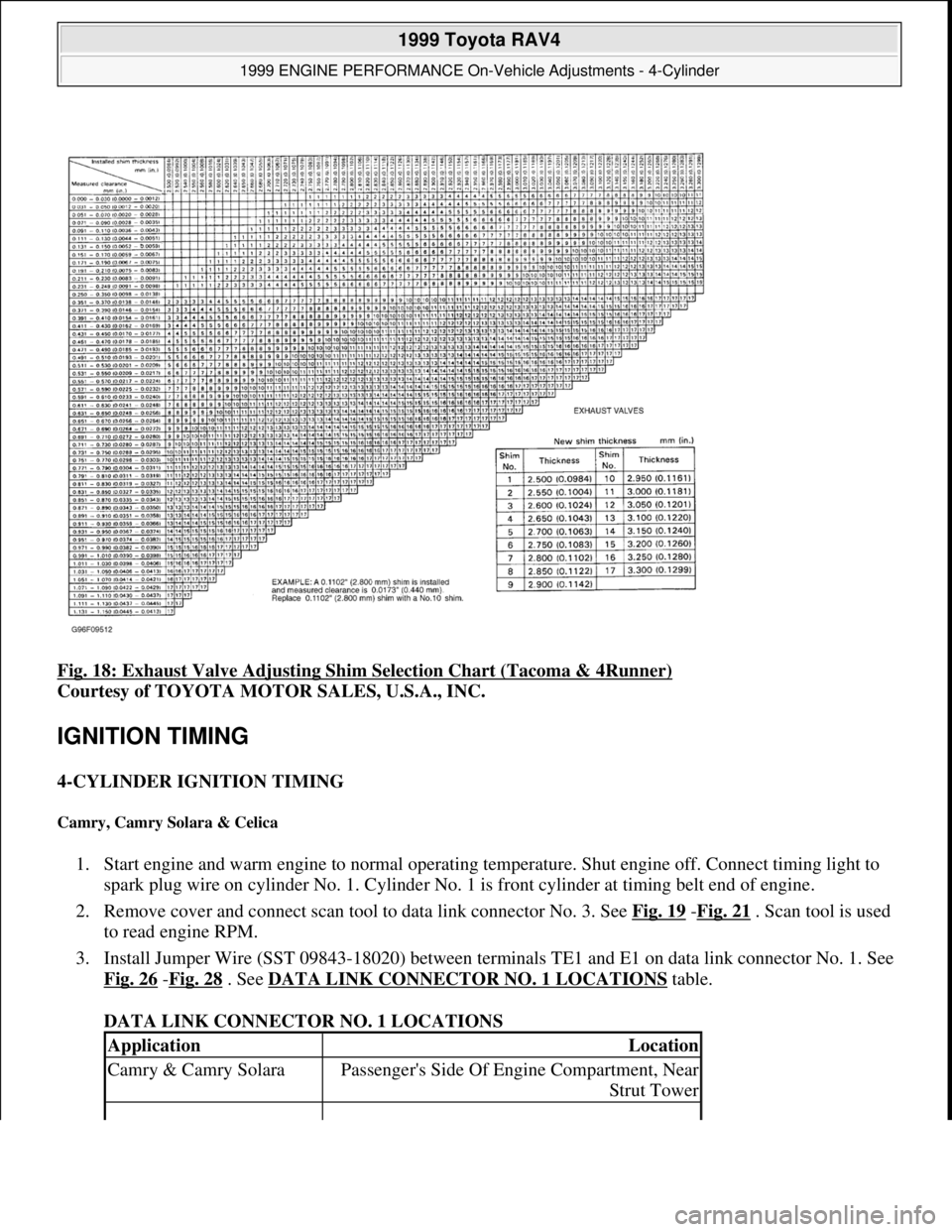
Fig. 18: Exhaust Valve Adjusting Shim Selection Chart (Tacoma & 4Runner)
Courtesy of TOYOTA MOTOR SALES, U.S.A., INC.
IGNITION TIMING
4-CYLINDER IGNITION TIMING
Camry, Camry Solara & Celica
1. Start engine and warm engine to normal operating temperature. Shut engine off. Connect timing light to
spark plug wire on cylinder No. 1. Cylinder No. 1 is front cylinder at timing belt end of engine.
2. Remove cover and connect scan tool to data link connector No. 3. See Fig. 19
-Fig. 21 . Scan tool is used
to read engine RPM.
3. Install Jumper Wire (SST 09843-18020) between terminals TE1 and E1 on data link connector No. 1. See
Fig. 26
-Fig. 28 . See DATA LINK CONNECTOR NO. 1 LOCATIONS table.
DATA LINK CONNECTOR NO. 1 LOCATIONS
ApplicationLocation
Camry & Camry SolaraPassenger's Side Of Engine Compartment, Near
Strut Tower
1999 Toyota RAV4
1999 ENGINE PERFORMANCE On-Vehicle Adjustments - 4-Cylinder
Microsoft
Sunday, November 22, 2009 10:25:31 AMPage 20 © 2005 Mitchell Repair Information Company, LLC.
Page 1072 of 1632
4. Apply parking brake. Place transaxle in Neutral. Start engine and maintain engine at 1000-1300 RPM for
5 seconds and then ensure engine returns to idle.
5. Timing marks are located on timing belt cover, near crankshaft pulley. Ensure base timing is within
specification at idle with transaxle in Neutral, and with A/C and all accessories off. See IGNITION
TIMING SPECIFICATIONS table.
6. Remove jumper wire from data link connector No. 1. Ensure ECM controlled timing is within
specification. See IGNITION TIMING SPECIFICATIONS
table. Shut engine off. Remove timing
light and scan tool.
Corolla
1. Start engine and warm engine to normal operating temperature. Shut engine off. Connect timing light to
spark plug wire on cylinder No. 1. Cylinder No. 1 is front cylinder at timing chain end of engine.
2. Connect scan tool to data link connector No. 3. See Fig. 22
. Scan tool is used to read engine RPM.
3. Install Jumper Wire (SST 09843-18020) between terminals TE1 and E1 on data link connector No. 1. See
Fig. 29
. Data link connector No. 1 is located at driver's side of engine compartment, near strut tower.
4. Apply parking brake. Place transaxle in Neutral. Start engine and maintain engine at 1000-1300 RPM for
5 seconds and then ensure engine returns to idle.
5. Timing marks are located on timing chain cover, near crankshaft pulley. Ensure base timing is within
specification at idle with transaxle in Neutral, and with A/C and all accessories off. See IGNITION
TIMING SPECIFICATIONS table.
6. Remove jumper wire from data link connector No. 1. Ensure ECM controlled timing is within
specification. See IGNITION TIMING SPECIFICATIONS
table. Shut engine off. Remove timing
light and scan tool.
RAV4
1. Start engine and warm engine to normal operating temperature. Shut engine off. Connect timing light to
spark plug wire on cylinder No. 1. Cylinder No. 1 is front cylinder at timing belt end of engine.
2. Remove cover from instrument panel and connect scan tool to data link connector No. 3. See Fig. 23
.
Scan tool is used to read engine RPM.
3. Install Jumper Wire (SST 09843-18020) between terminals TE1 and E1 on data link connector No. 1. See
Fig. 30
. Data link connector No. 1 is located on timing belt end of engine, above generator.
4. Apply parking brake. Place transaxle in Neutral. Start engine and allow engine to idle.
5. Timing marks are located on timing belt cover, near crankshaft pulley. Ensure base timing is within
specification at idle with transaxle in Neutral, and with A/C and all accessories off. See IGNITION
TIMING SPECIFICATIONS table.
6. Remove jumper wire from data link connector No. 1. Ensure ECM controlled timing is within
specification. See IGNITION TIMING SPECIFICATIONS
table. Shut engine off. Remove timing
li
ght and scan tool.
CelicaDriver's Side Rear Corner Of Engine
Compartment, Near Brake Booster
1999 Toyota RAV4
1999 ENGINE PERFORMANCE On-Vehicle Adjustments - 4-Cylinder
Microsoft
Sunday, November 22, 2009 10:25:31 AMPage 21 © 2005 Mitchell Repair Information Company, LLC.
Page 1073 of 1632
Tacoma & 4Runner
1. Start engine and warm engine to normal operating temperature. Shut engine off. Connect timing light to
spark plug wire on cylinder No. 1. Cylinder No. 1 is front cylinder at timing chain end of engine.
2. Connect scan tool to data link connector No. 3. See Fig. 24
and Fig. 25 . Scan tool is used to read engine
RPM.
3. Install Jumper Wire (SST 09843-18020) between terminals TE1 and E1 on data link connector No. 1. See
Fig. 31
. Data link connector No. 1 is located on end of intake manifold at front of engine.
4. Apply parking brake. Place transmission in Neutral. Start engine. Maintain engine at 1000 RPM for 5
seconds and then ensure engine returns to idle.
5. Timing marks are located on timing chain cover, near crankshaft pulley. Ensure base timing is within
specification at idle with transmission in Neutral, and with A/C and all accessories off. See IGNITION
TIMING SPECIFICATIONS table.
6. Remove jumper wire from data link connector No. 1. Ensure ECM controlled timing is within
specification. See IGNITION TIMING SPECIFICATIONS
table. Shut engine off. Remove timing
light and scan tool.
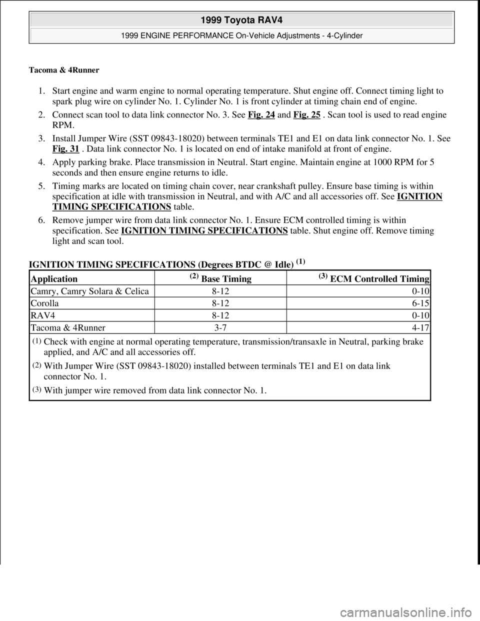
IGNITION TIMING SPECIFICATIONS (Degrees BTDC @ Idle)
(1)
Application(2) Base Timing(3) ECM Controlled Timing
Camry, Camry Solara & Celica8-120-10
Corolla8-126-15
RAV48-120-10
Tacoma & 4Runner3-74-17
(1)Check with engine at normal operating temperature, transmission/transaxle in Neutral, parking brake
applied, and A/C and all accessories off.
(2)With Jumper Wire (SST 09843-18020) installed between terminals TE1 and E1 on data link
connector No. 1.
(3)With jumper wire removed from data link connector No. 1.
1999 Toyota RAV4
1999 ENGINE PERFORMANCE On-Vehicle Adjustments - 4-Cylinder
Microsoft
Sunday, November 22, 2009 10:25:31 AMPage 22 © 2005 Mitchell Repair Information Company, LLC.
Page 1157 of 1632
ohmmeter between clutch start switch terminals. Depress clutch pedal. If continuity does not exist, adjust or
replace clutch start switch. If continuity exists, switch is functioning properly.
CLUTCH START CANCEL SWITCH TEST
Tacoma & 4Runner
1. Remove clutch start cancel switch. Switch is located on left side of instrument panel. Connect negative
lead of ohmmeter to terminal No. 1. See Fig. 1
. Check for continuity between clutch start cancel switch
terminals No. 1 and 2 and terminals No. 1 and 3. If continuity does not exist, go to next step. If continuity
exists, replace clutch start cancel switch.
2. Check for continuity between clutch start cancel switch terminals No. 2 and 3. If continuity exists, replace
clutch start cancel switch. If continuity does not exist, check operation of switch by applying battery
voltage to switch. Using jumper wires, connect positive battery lead to terminal No. 3 and negative
battery lead to terminal No. 1 of clutch start cancel switch.
3. Connect ohmmeter positive lead to terminal No. 2 and negative lead to terminal No. 1 of clutch start
cancel switch. Continuity should not exist. Depress clutch start cancel switch. Continuity should exist and
indicator light on clutch start cancel switch should be on. If switch does not test as specified, replace
switch.
Tundra
1. Locate switch on left side of instrument panel. Remove left lower instrument panel. Disconnect wiring
harness connector from switch pigtail connector. Remove switch base from instrument panel. Remove
switch from base.
2. Check for continuity between clutch start cancel switch connector terminals No. 1 and 3. See Fig. 2
. If
continuity exists, replace clutch start cancel switch. If continuity does not exist, go to next step.
3. Using jumper wires, connect positive battery terminal to clutch start cancel switch connector terminal No.
7 and ground to terminal No. 5. No continuity should exist between terminals No. 1 and 3. Press switch
and ensure switch light illuminates. With switch pressed, continuity should exist between terminals No. 1
and 3.
4. Remove jumper wire from clutch start cancel switch connector terminal No. 5. Ensure continuity does not
exist between clutch start cancel switch connector terminals No. 1 and 3. If continuity is not as specified,
replace clutch start cancel switch.
1999 Toyota RAV4
1999-2000 STARTING & CHARGING SYSTEMS Starters
Microsoft
Sunday, November 22, 2009 10:19:18 AMPage 2 © 2005 Mitchell Repair Information Company, LLC.
Page 1166 of 1632
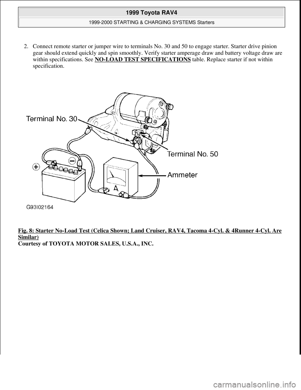
2. Connect remote starter or jumper wire to terminals No. 30 and 50 to engage starter. Starter drive pinion
gear should extend quickly and spin smoothly. Verify starter amperage draw and battery voltage draw are
within specifications. See NO
-LOAD TEST SPECIFICATIONS table. Replace starter if not within
specification.
Fig. 8: Starter No
-Load Test (Celica Shown; Land Cruiser, RAV4, Tacoma 4-Cyl. & 4Runner 4-Cyl. Are
Similar)
Courtesy of TOYOTA MOTOR SALES, U.S.A., INC.
1999 Toyota RAV4
1999-2000 STARTING & CHARGING SYSTEMS Starters
Microsoft
Sunday, November 22, 2009 10:19:18 AMPage 11 © 2005 Mitchell Repair Information Company, LLC.
Page 1498 of 1632
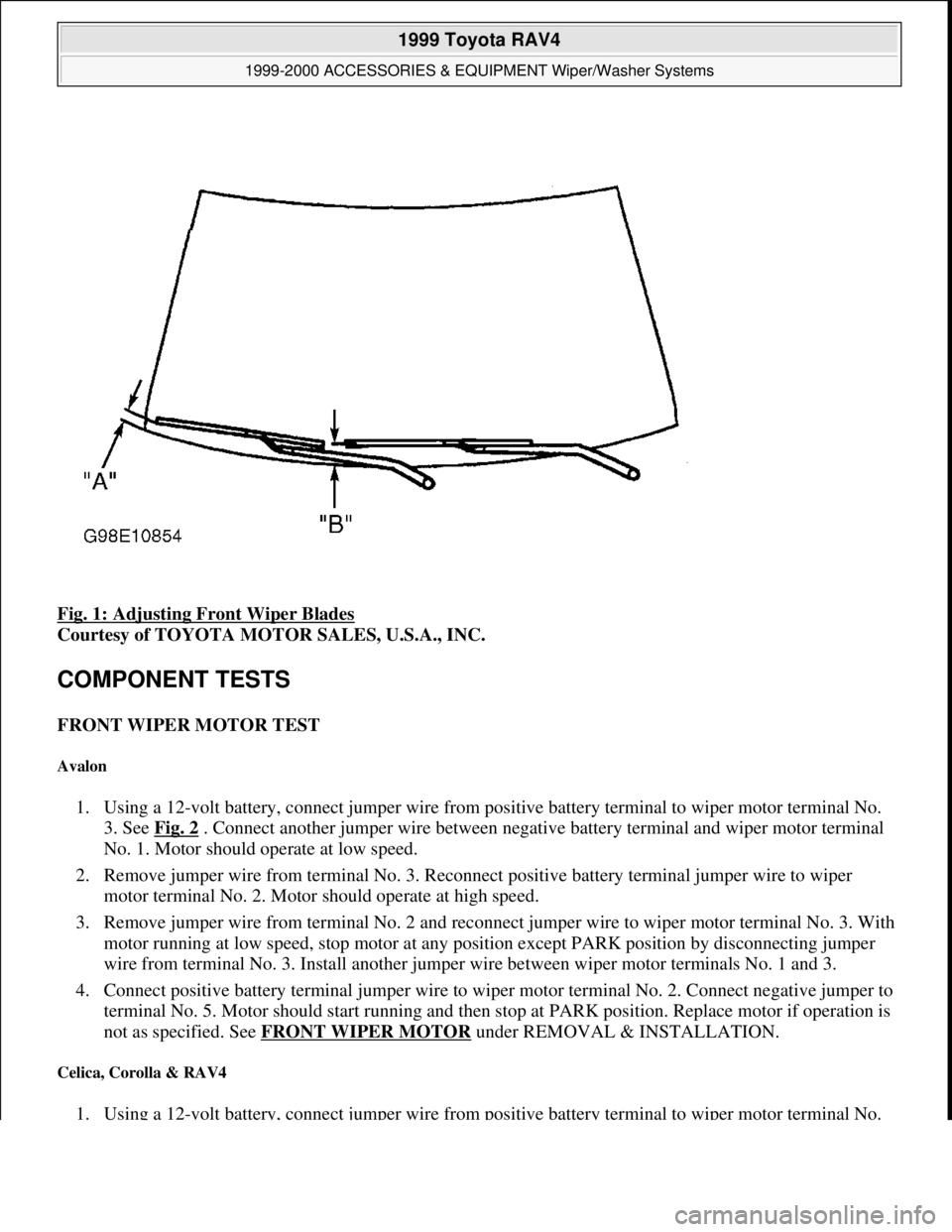
Fig. 1: Adjusting Front Wiper Blades
Courtesy of TOYOTA MOTOR SALES, U.S.A., INC.
COMPONENT TESTS
FRONT WIPER MOTOR TEST
Avalon
1. Using a 12-volt battery, connect jumper wire from positive battery terminal to wiper motor terminal No.
3. See Fig. 2
. Connect another jumper wire between negative battery terminal and wiper motor terminal
No. 1. Motor should operate at low speed.
2. Remove jumper wire from terminal No. 3. Reconnect positive battery terminal jumper wire to wiper
motor terminal No. 2. Motor should operate at high speed.
3. Remove jumper wire from terminal No. 2 and reconnect jumper wire to wiper motor terminal No. 3. With
motor running at low speed, stop motor at any position except PARK position by disconnecting jumper
wire from terminal No. 3. Install another jumper wire between wiper motor terminals No. 1 and 3.
4. Connect positive battery terminal jumper wire to wiper motor terminal No. 2. Connect negative jumper to
terminal No. 5. Motor should start running and then stop at PARK position. Replace motor if operation is
not as specified. See FRONT WIPER MOTOR
under REMOVAL & INSTALLATION.
Celica, Corolla & RAV4
1. Using a 12-volt battery, connect jumper wire from positive battery terminal to wiper motor terminal No.
1999 Toyota RAV4
1999-2000 ACCESSORIES & EQUIPMENT Wiper/Washer Systems
Microsoft
Sunday, November 22, 2009 11:01:19 AMPage 3 © 2005 Mitchell Repair Information Company, LLC.