charging TOYOTA RAV4 1996 Service Repair Manual
[x] Cancel search | Manufacturer: TOYOTA, Model Year: 1996, Model line: RAV4, Model: TOYOTA RAV4 1996Pages: 1632, PDF Size: 41.64 MB
Page 10 of 1632
wiring harness between ABS control relay and DLC1. Repair or replace as necessary. See WIRING
DIAGRAMS .
2. If ABS warning light is on, go to next step. If ABS warning light is off, check for open or short circuit in
wiring harness between ECU-IG fuse and ABS ECU. Repair as necessary. See WIRING DIAGRAMS
.
3. Start engine and check charging system voltage. If voltage is 10-16 volts, go to next step. If voltage is not
10-16 volts, diagnose charging system. Repair as necessary.
4. Turn ignition off. Disconnect appropriate ABS ECU connector supporting IG1 terminal. See Fig. 3
. Turn
ignition switch to ON position. Ensure ABS warning light turns off. If light turns off, replace ABS ECU.
If light does not turn off, check for short circuit in wiring harness between combination meter (instrument
panel) and ABS ECU, or between combination meter and DLC1. Repair as necessary. See WIRING
DIAGRAMS .
DIAGNOSTIC TESTS
DTC 11 & DTC 12: ABS CONTROL (SOLENOID) RELAY CIRCUIT
Circuit Description
This relay supplies power to each ABS solenoid. After ignition switch is turned to ON position, if initial check
is okay, this relay turns on. If malfunction occurs in ABS control relay circuit, ABS ECU cuts off current to
ABS control relay and prohibits ABS control.
DTC Detecting Condition
Detection of following conditions may set DTC 11 or DTC 12 if condition occurs for .2 seconds or more:
If voltage at ABS control relay connector terminal A9-1 is less than 1.5 volts and voltage at connector
terminal A9-5 is zero volts, DTC 11 may set.
If voltage at ABS control relay connector terminal A9-1 is 10-14 volts and voltage at connector terminal
A9-5 is 10-14 volts, DTC 12 may set.
Diagnostic Procedure
1. Disconnect ABS control relay 6-pin connector A9, located in engine compartment at front of vehicle. See
Fig. 1
. Measure voltage between connector terminals A9-2 and A9-6. See Fig. 4 . If voltage is 10-14
volts, go to next step. If voltage is not 10-14 volts, repair wiring harness between ground, battery and
ABS control relay.
2. Measure resistance between ABS control relay terminal A9-5 and appropriate ABS ECU terminals. See
ABS ECU
-TO-ACTUATOR CIRCUIT IDENTIFICATION/RESISTANCE VALUES . See Fig. 3 .
If resistance on every circuit is between 26-40 ohms, go to next step. If resistance is not as specified,
check for open or short circuit in appropriate wiring between ABS control relay, ABS actuator and ABS
ECU. See WIRING DIAGRAMS
. Repair as necessary. If wiring is okay, replace ABS actuator.
ABS ECU-TO-ACTUATOR CIRCUIT IDENTIFICATION/RESISTANCE VALUES
CircuitABS ECU
Connector/TerminalWire Color
1999 Toyota RAV4
1999-2000 BRAKES Anti-Lock - RAV4
Microsoft
Sunday, November 22, 2009 10:06:17 AMPage 10 © 2005 Mitchell Repair Information Company, LLC.
Page 17 of 1632
DTC Detecting Condition
Detection of the following condition may set DTC 41:
At vehicle speed of about 2 MPH or more, if voltage at ABS ECU terminal IG1 is less than 9.5 volts for
10 seconds or more, DTC 41 may set.
Diagnostic Procedure
1. Check charging system voltage. If voltage is 10-14 volts, system is okay. Go to next step. If voltage is not
10-14 volts, repair charging system. Ensure system fuses are okay.
2. Turn ignition off. Remove ABS ECU. Do not disconnect electrical connectors. Turn ignition switch to
ON position. Measure voltage between terminals IG1 and GND at ABS ECU harness connector. See Fig.
3 . If voltage is 10-14 volts, turn ignition off. Condition may be intermittent. Check ABS ECU connectors
for poor connection or damage. Repair as necessary. If connectors are okay, replace ABS ECU. If voltage
is not as specified, go to next step.
3. Measure resistance between ground and GND terminals at ABS ECU harness connector. See Fig. 3
. If
resistance is one ohm or less, go to next step. If resistance is more than one ohm, repair ground circuit
wiring. See WIRING DIAGRAMS
.
4. Remove ECU-IG fuse from instrument panel junction block. If fuse is blown, check for short circuit in all
wiring harnesses and components connected to ECU-IG fuse (ECM, A/C, cruise control, deceleration
sensor, combination meter, sun roof, shift lock, transmission pattern select switch). See WIRING
DIAGRAMS . Repair as necessary. If fuse is not blown, check for open circuit in wiring harness between
battery and ABS ECU. Repair as necessary.
DTC 43 & DTC 45: DECELERATION SENSOR MALFUNCTION (4WD MODELS ONLY)
DTC Detecting Conditions
Detection of the following conditions may set DTCs 43 or 45:
On 2-door models, if output voltage from deceleration sensor does not change for 16 consecutive times or
more when vehicle speed is decreased from 19 MPH to zero MPH, DTC 43 will set.
On 4-door models, after battery cables are connected, if input from deceleration sensor does not change at
one cycle (zero MPH to 19 MPH or more, then back to zero) for 16 consecutive times, DTC 43 will set.
When brake pedal is not depressed at vehicle speed of 3 MPH or more, and forward and backward force
(force of more than 0.4 "G") is detected for 30 seconds or more, DTC 43 will set.
On 2-door models, at vehicle speed of 19 MPH or more, if deceleration sensor output and vehicle
acceleration from wheel speed remains abnormally different for one minute or more, DTC 45 will set.
Diagnostic Procedure
1. Check deceleration sensor. See DECELERATION SENSOR CHECK under COMPONENT TESTS.
Replace sensor as necessary. If sensor is okay, go to next step.
2. Check for open or short circuit in wiring harness between deceleration sensor and ABS ECU. See
WIRING DIAGRAMS
. Repair as necessary. If wiring harness is okay, replace ABS ECU.
1999 Toyota RAV4
1999-2000 BRAKES Anti-Lock - RAV4
Microsoft
Sunday, November 22, 2009 10:06:17 AMPage 17 © 2005 Mitchell Repair Information Company, LLC.
Page 26 of 1632
1. Check charging system voltage. Ensure 10-14 volts is present. If charging system voltage is okay, go to
next step. If charging system voltage is not okay, check and repair charging system.
2. Turn ignition switch to ON position. Ensure ABS warning light comes on, then goes out after 3 seconds.
If ABS warning light does not illuminate, check fuse, bulb, and wiring harness. See ABS WARNING
LIGHT under DIAGNOSIS & TESTING. Turn ignition off.
3. Using a jumper wire, jumper terminals Ts and E
1 of DLC1. DLC1 is located in engine compartment on
left side of engine. See Fig. 2
. Ensure ABS warning light blinks 4 times per second. If ABS light does
not blink, go to ABS WARNING LIGHT
under DIAGNOSIS & TESTING. If ABS warning light
blinks, go to next step.
4. Using a floor jack, slowly jack up rear of vehicle. On vehicles with 215/70R16 tires, raise vehicle to a
height of 25.59-27.95" (650-710 mm). On vehicles with 235/60R16 tires, raise vehicle to a height of
26.38-28.74" (670-730 mm). If ABS warning light illuminates at specified height, check deceleration
sensor installation. If installation is okay, replace deceleration sensor. Lower vehicle.
5. Using a floor jack, slowly jack up front of vehicle. On vehicles with 215/70R16 tires, raise vehicle to a
height of 21.20-23.56" (550-610 mm). On vehicles with 235/60R16 tires, raise vehicle to a height of
22.44-24.80" (570-630 mm). If ABS warning light illuminates at specified height, check deceleration
sensor installation. If installation is okay, replace deceleration sensor. Lower vehicle.
6. Drive vehicle straight ahead at speed of 13 MPH or more. Lightly depress brake pedal. Ensure ABS
warning light pattern is normal (light blinks 4 times per second).
7. While driving vehicle straight ahead at speed of 13 MPH or more, moderately depress brake pedal.
Ensure ABS warning light illuminates in a solid pattern (light does not blink) while braking.
8. While driving vehicle straight ahead at speed of 13 MPH or more, firmly depress brake pedal. Ensure
ABS warning light illumination pattern changes from a solid pattern (light does not blink) to a normal
pattern (light blinks 4 times per second), then back to a solid pattern while braking.
9. If ABS warning light does not illuminate as described in steps 6 -8 , check deceleration sensor
installation. If installation is okay, replace deceleration sensor. Stop vehicle and turn ignition off. Remove
jumper wire from DLC1.
REMOVAL & INSTALLATION
ACTUATOR
Removal & Installation
Turn ignition off. Disconnect brakelines attached to actuator. Remove power steering hose retaining bracket
bolt and power steering reservoir. Disconnect actuator electrical connectors. Remove bolts, nuts and washers.
Remove actuator assembly. Remove actuator from actuator bracket. Remove cushions and holders from NOTE: When measuring vehicle height in following steps, measure at center of
lower body of vehicle.
WARNING:Hydraulic system may be under high pressure. Use caution when opening
hydraulic system.
1999 Toyota RAV4
1999-2000 BRAKES Anti-Lock - RAV4
Microsoft
Sunday, November 22, 2009 10:06:17 AMPage 26 © 2005 Mitchell Repair Information Company, LLC.
Page 56 of 1632
3. With squib circuit connector disconnected, insert paper into female terminal, sliding it under shorting bar
spring. This lifts the spring, breaking the circuit and allowing the test procedure to be performed as
specified.
TESTING - DIAGNOSTIC
NO CODES - SOURCE VOLTAGE DROP
1. Disconnect negative battery cable. Wait at least 90 seconds. Remove steering wheel pad. See
STEERING WHEEL PAD & SPIRAL CABLE
under REMOVAL & INSTALLATION. Disconnect
passenger-side air bag harness connector, accessible through finish plate in glove box. See Fig. 2
.
Disconnect air bag sensor assembly connector.
2. Reconnect negative battery cable. Turn ignition switch to ON position. Measure voltage between ground
and terminals IG2 and ACC of air bag sensor connector. See Fig. 13
. Operate electrical components
(defogger, wiper, headlights, heater blower, etc.). If voltage is 8-14 volts, go to next step. If voltage is not
8-14 volts, check harness between battery and air bag sensor assembly and check battery and charging
system.
3. Turn ignition switch to LOCK position. Connect steering wheel pad connector. Connect passenger-side
air bag connector. Turn ignition switch to ON position. Operate electrical components as in step 2) and
check that SRS warning light goes off. If light does not go off, check diagnostic trouble code and go to
appropriate CODE under TESTING - DIAGNOSTIC. If a normal code is output, replace air bag sensor
assembly. If warning light goes off, no problem detected at this time.
CODE 11
1. Disconnect negative battery cable. Wait at least 90 seconds. Remove steering wheel pad. See
STEERING WHEEL PAD & SPIRAL CABLE
under REMOVAL & INSTALLATION. Disconnect
passenger-side air bag harness connector, accessible through finish plate in glove box. See Fig. 2
.
Disconnect air bag sensor assembly connector.
2. Measure resistance on spiral cable side of connector between spiral cable and steering wheel pad between
D+, D- and ground. If resistance is 1000 ohms or more, go to next step. If resistance is less than 1000
ohms, go to step 7).
3. Measure resistance on air ba
g sensor assembly side of connector between air bag sensor and passenger- WARNING:Paper must not be thicker than male terminal. If paper is thicker,
connector terminal may be damaged, possible resulting in system
fault.
NOTE: Use Diagnosis Check Wiring (09843-18020) when connecting jumper wire
between terminals of DLC. Spiral cable upper connector is same as steering
wheel pad (squib) connector. Spiral cable lower connector (located under
steering column) connects the harness between spiral cable and center air bag
sensor.
NOTE: During testing, if codes other than Code 11 are displayed, disregard them.
1996 Toyota 4Runner
AIR BAG RESTRAINT SYSTEM 1996 ACCESSORIES/SAFETY EQUIPMENT Toyota Air Bag Restraint System
Microsoft
Tuesday, August 18, 2009 7:33:32 PMPage 22 © 2005 Mitchell Repair Information Company, LLC.
Page 59 of 1632
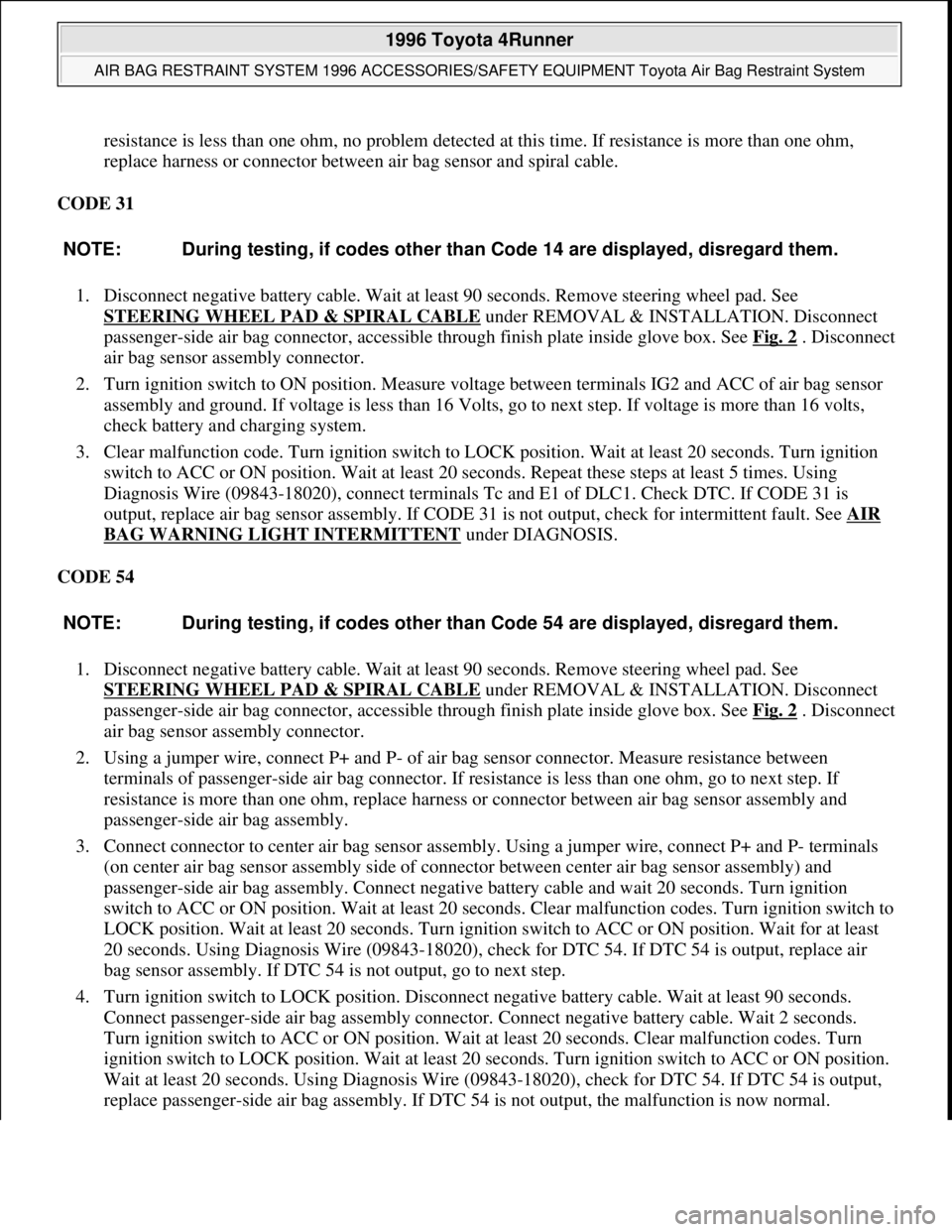
resistance is less than one ohm, no problem detected at this time. If resistance is more than one ohm,
replace harness or connector between air bag sensor and spiral cable.
CODE 31
1. Disconnect negative battery cable. Wait at least 90 seconds. Remove steering wheel pad. See
STEERING WHEEL PAD & SPIRAL CABLE
under REMOVAL & INSTALLATION. Disconnect
passenger-side air bag connector, accessible through finish plate inside glove box. See Fig. 2
. Disconnect
air bag sensor assembly connector.
2. Turn ignition switch to ON position. Measure voltage between terminals IG2 and ACC of air bag sensor
assembly and ground. If voltage is less than 16 Volts, go to next step. If voltage is more than 16 volts,
check battery and charging system.
3. Clear malfunction code. Turn ignition switch to LOCK position. Wait at least 20 seconds. Turn ignition
switch to ACC or ON position. Wait at least 20 seconds. Repeat these steps at least 5 times. Using
Diagnosis Wire (09843-18020), connect terminals Tc and E1 of DLC1. Check DTC. If CODE 31 is
output, replace air bag sensor assembly. If CODE 31 is not output, check for intermittent fault. See AIR
BAG WARNING LIGHT INTERMITTENT under DIAGNOSIS.
CODE 54
1. Disconnect negative battery cable. Wait at least 90 seconds. Remove steering wheel pad. See
STEERING WHEEL PAD & SPIRAL CABLE
under REMOVAL & INSTALLATION. Disconnect
passenger-side air bag connector, accessible through finish plate inside glove box. See Fig. 2
. Disconnect
air bag sensor assembly connector.
2. Using a jumper wire, connect P+ and P- of air bag sensor connector. Measure resistance between
terminals of passenger-side air bag connector. If resistance is less than one ohm, go to next step. If
resistance is more than one ohm, replace harness or connector between air bag sensor assembly and
passenger-side air bag assembly.
3. Connect connector to center air bag sensor assembly. Using a jumper wire, connect P+ and P- terminals
(on center air bag sensor assembly side of connector between center air bag sensor assembly) and
passenger-side air bag assembly. Connect negative battery cable and wait 20 seconds. Turn ignition
switch to ACC or ON position. Wait at least 20 seconds. Clear malfunction codes. Turn ignition switch to
LOCK position. Wait at least 20 seconds. Turn ignition switch to ACC or ON position. Wait for at least
20 seconds. Using Diagnosis Wire (09843-18020), check for DTC 54. If DTC 54 is output, replace air
bag sensor assembly. If DTC 54 is not output, go to next step.
4. Turn ignition switch to LOCK position. Disconnect negative battery cable. Wait at least 90 seconds.
Connect passenger-side air bag assembly connector. Connect negative battery cable. Wait 2 seconds.
Turn ignition switch to ACC or ON position. Wait at least 20 seconds. Clear malfunction codes. Turn
ignition switch to LOCK position. Wait at least 20 seconds. Turn ignition switch to ACC or ON position.
Wait at least 20 seconds. Using Diagnosis Wire (09843-18020), check for DTC 54. If DTC 54 is output,
replace passen
ger-side air bag assembly. If DTC 54 is not output, the malfunction is now normal. NOTE: During testing, if codes other than Code 14 are displayed, disregard them.
NOTE: During testing, if codes other than Code 54 are displayed, disregard them.
1996 Toyota 4Runner
AIR BAG RESTRAINT SYSTEM 1996 ACCESSORIES/SAFETY EQUIPMENT Toyota Air Bag Restraint System
Microsoft
Tuesday, August 18, 2009 7:33:32 PMPage 25 © 2005 Mitchell Repair Information Company, LLC.
Page 91 of 1632
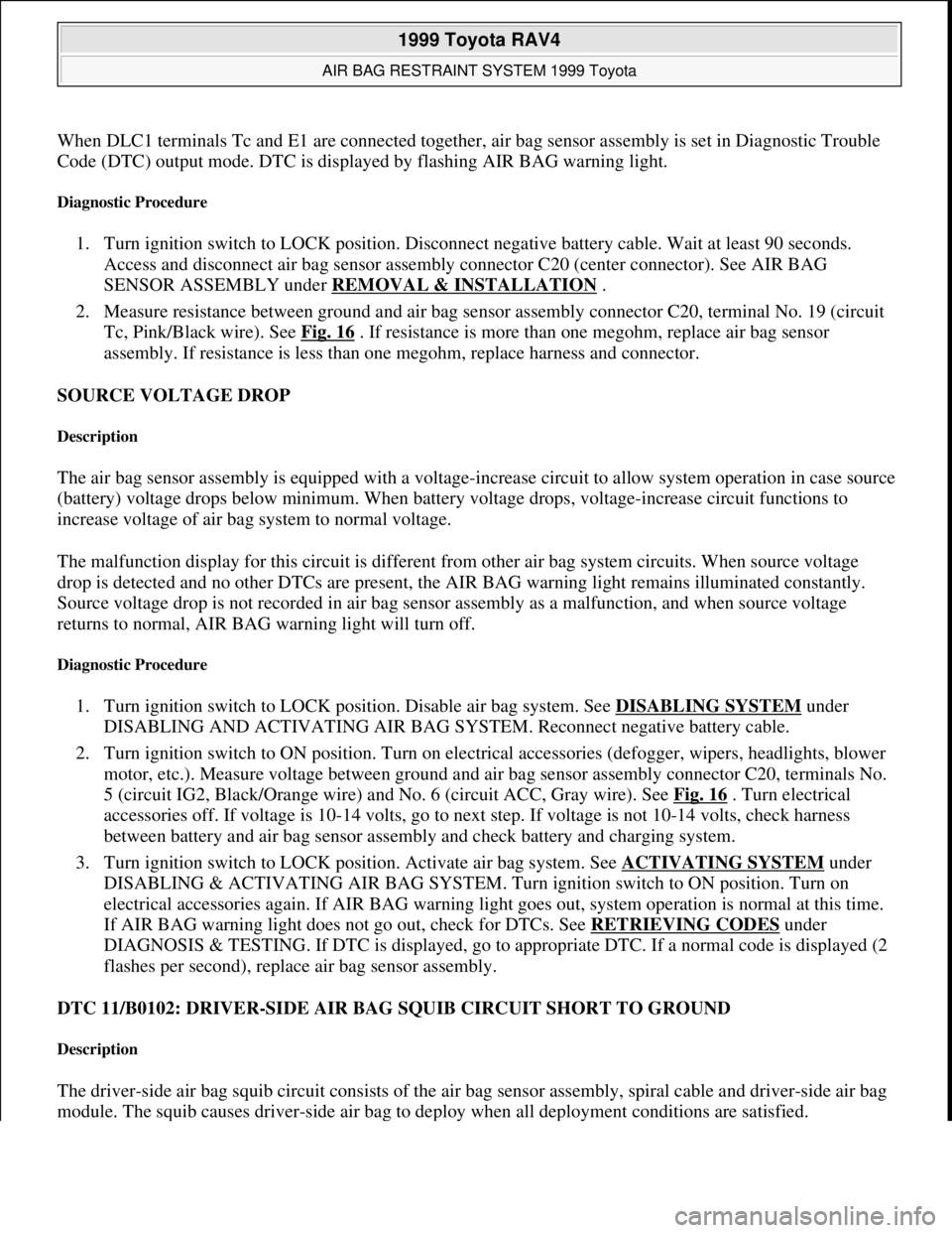
When DLC1 terminals Tc and E1 are connected together, air bag sensor assembly is set in Diagnostic Trouble
Code (DTC) output mode. DTC is displayed by flashing AIR BAG warning light.
Diagnostic Procedure
1. Turn ignition switch to LOCK position. Disconnect negative battery cable. Wait at least 90 seconds.
Access and disconnect air bag sensor assembly connector C20 (center connector). See AIR BAG
SENSOR ASSEMBLY under REMOVAL & INSTALLATION
.
2. Measure resistance between ground and air bag sensor assembly connector C20, terminal No. 19 (circuit
Tc, Pink/Black wire). See Fig. 16
. If resistance is more than one megohm, replace air bag sensor
assembly. If resistance is less than one megohm, replace harness and connector.
SOURCE VOLTAGE DROP
Description
The air bag sensor assembly is equipped with a voltage-increase circuit to allow system operation in case source
(battery) voltage drops below minimum. When battery voltage drops, voltage-increase circuit functions to
increase voltage of air bag system to normal voltage.
The malfunction display for this circuit is different from other air bag system circuits. When source voltage
drop is detected and no other DTCs are present, the AIR BAG warning light remains illuminated constantly.
Source voltage drop is not recorded in air bag sensor assembly as a malfunction, and when source voltage
returns to normal, AIR BAG warning light will turn off.
Diagnostic Procedure
1. Turn ignition switch to LOCK position. Disable air bag system. See DISABLING SYSTEM under
DISABLING AND ACTIVATING AIR BAG SYSTEM. Reconnect negative battery cable.
2. Turn ignition switch to ON position. Turn on electrical accessories (defogger, wipers, headlights, blower
motor, etc.). Measure voltage between ground and air bag sensor assembly connector C20, terminals No.
5 (circuit IG2, Black/Orange wire) and No. 6 (circuit ACC, Gray wire). See Fig. 16
. Turn electrical
accessories off. If voltage is 10-14 volts, go to next step. If voltage is not 10-14 volts, check harness
between battery and air bag sensor assembly and check battery and charging system.
3. Turn ignition switch to LOCK position. Activate air bag system. See ACTIVATING SYSTEM
under
DISABLING & ACTIVATING AIR BAG SYSTEM. Turn ignition switch to ON position. Turn on
electrical accessories again. If AIR BAG warning light goes out, system operation is normal at this time.
If AIR BAG warning light does not go out, check for DTCs. See RETRIEVING CODES
under
DIAGNOSIS & TESTING. If DTC is displayed, go to appropriate DTC. If a normal code is displayed (2
flashes per second), replace air bag sensor assembly.
DTC 11/B0102: DRIVER-SIDE AIR BAG SQUIB CIRCUIT SHORT TO GROUND
Description
The driver-side air bag squib circuit consists of the air bag sensor assembly, spiral cable and driver-side air bag
module. The squib causes drive
r-side air bag to deploy when all deployment conditions are satisfied.
1999 Toyota RAV4
AIR BAG RESTRAINT SYSTEM 1999 Toyota
Microsoft
Sunday, November 22, 2009 10:33:23 AMPage 28 © 2005 Mitchell Repair Information Company, LLC.
Page 99 of 1632
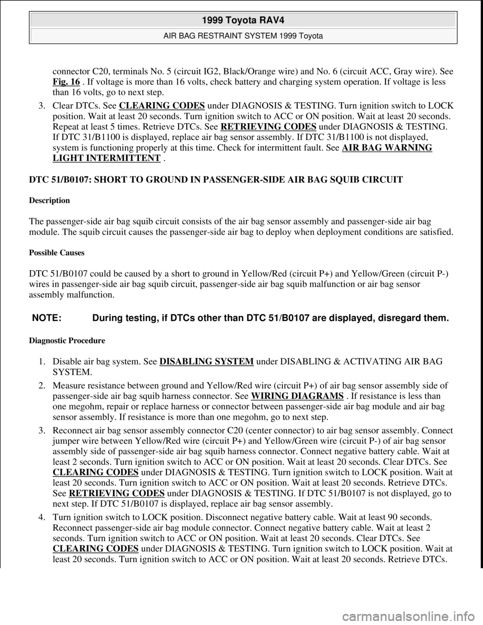
connector C20, terminals No. 5 (circuit IG2, Black/Orange wire) and No. 6 (circuit ACC, Gray wire). See
Fig. 16
. If voltage is more than 16 volts, check battery and charging system operation. If voltage is less
than 16 volts, go to next step.
3. Clear DTCs. See CLEARING CODES
under DIAGNOSIS & TESTING. Turn ignition switch to LOCK
position. Wait at least 20 seconds. Turn ignition switch to ACC or ON position. Wait at least 20 seconds.
Repeat at least 5 times. Retrieve DTCs. See RETRIEVING CODES
under DIAGNOSIS & TESTING.
If DTC 31/B1100 is displayed, replace air bag sensor assembly. If DTC 31/B1100 is not displayed,
system is functioning properly at this time. Check for intermittent fault. See AIR BAG WARNING
LIGHT INTERMITTENT .
DTC 51/B0107: SHORT TO GROUND IN PASSENGER-SIDE AIR BAG SQUIB CIRCUIT
Description
The passenger-side air bag squib circuit consists of the air bag sensor assembly and passenger-side air bag
module. The squib circuit causes the passenger-side air bag to deploy when deployment conditions are satisfied.
Possible Causes
DTC 51/B0107 could be caused by a short to ground in Yellow/Red (circuit P+) and Yellow/Green (circuit P-)
wires in passenger-side air bag squib circuit, passenger-side air bag squib malfunction or air bag sensor
assembly malfunction.
Diagnostic Procedure
1. Disable air bag system. See DISABLING SYSTEM under DISABLING & ACTIVATING AIR BAG
SYSTEM.
2. Measure resistance between ground and Yellow/Red wire (circuit P+) of air bag sensor assembly side of
passenger-side air bag squib harness connector. See WIRING DIAGRAMS
. If resistance is less than
one megohm, repair or replace harness or connector between passenger-side air bag module and air bag
sensor assembly. If resistance is more than one megohm, go to next step.
3. Reconnect air bag sensor assembly connector C20 (center connector) to air bag sensor assembly. Connect
jumper wire between Yellow/Red wire (circuit P+) and Yellow/Green wire (circuit P-) of air bag sensor
assembly side of passenger-side air bag squib harness connector. Connect negative battery cable. Wait at
least 2 seconds. Turn ignition switch to ACC or ON position. Wait at least 20 seconds. Clear DTCs. See
CLEARING CODES
under DIAGNOSIS & TESTING. Turn ignition switch to LOCK position. Wait at
least 20 seconds. Turn ignition switch to ACC or ON position. Wait at least 20 seconds. Retrieve DTCs.
See RETRIEVING CODES
under DIAGNOSIS & TESTING. If DTC 51/B0107 is not displayed, go to
next step. If DTC 51/B0107 is displayed, replace air bag sensor assembly.
4. Turn ignition switch to LOCK position. Disconnect negative battery cable. Wait at least 90 seconds.
Reconnect passenger-side air bag module connector. Connect negative battery cable. Wait at least 2
seconds. Turn ignition switch to ACC or ON position. Wait at least 20 seconds. Clear DTCs. See
CLEARING CODES
under DIAGNOSIS & TESTING. Turn ignition switch to LOCK position. Wait at
least 20 seconds. Turn ignition switch to ACC or ON position. Wait at least 20 seconds. Retrieve DTCs. NOTE: During testing, if DTCs other than DTC 51/B0107 are displayed, disregard them.
1999 Toyota RAV4
AIR BAG RESTRAINT SYSTEM 1999 Toyota
Microsoft
Sunday, November 22, 2009 10:33:23 AMPage 36 © 2005 Mitchell Repair Information Company, LLC.
Page 402 of 1632
1999-2000 STARTING & CHARGING SYSTEMS
Generators & Regulators
DESCRIPTION & OPERATION
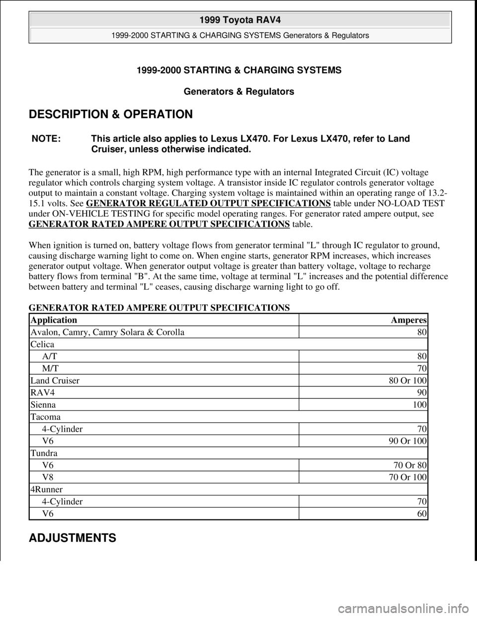
The generator is a small, high RPM, high performance type with an internal Integrated Circuit (IC) voltage
regulator which controls charging system voltage. A transistor inside IC regulator controls generator voltage
output to maintain a constant voltage. Charging system voltage is maintained within an operating range of 13.2-
15.1 volts. See GENERATOR REGULATED OUTPUT SPECIFICATIONS
table under NO-LOAD TEST
under ON-VEHICLE TESTING for specific model operating ranges. For generator rated ampere output, see
GENERATOR RATED AMPERE OUTPUT SPECIFICATIONS
table.
When ignition is turned on, battery voltage flows from generator terminal "L" through IC regulator to ground,
causing discharge warning light to come on. When engine starts, generator RPM increases, which increases
generator output voltage. When generator output voltage is greater than battery voltage, voltage to recharge
battery flows from terminal "B". At the same time, voltage at terminal "L" increases and the potential difference
between battery and terminal "L" ceases, causing discharge warning light to go off.
GENERATOR RATED AMPERE OUTPUT SPECIFICATIONS
ADJUSTMENTS
NOTE: This article also applies to Lexus LX470. For Lexus LX470, refer to Land
Cruiser, unless otherwise indicated.
ApplicationAmperes
Avalon, Camry, Camry Solara & Corolla80
Celica
A/T80
M/T70
Land Cruiser80 Or 100
RAV490
Sienna100
Tacoma
4-Cylinder70
V690 Or 100
Tundra
V670 Or 80
V870 Or 100
4Runner
4-Cylinder70
V660
1999 Toyota RAV4
1999-2000 STARTING & CHARGING SYSTEMS Generators & Regulators
1999 Toyota RAV4
1999-2000 STARTING & CHARGING SYSTEMS Generators & Regulators
Microsoft
Sunday, November 22, 2009 10:13:07 AMPage 1 © 2005 Mitchell Repair Information Company, LLC.
Microsoft
Sunday, November 22, 2009 10:13:12 AMPage 1 © 2005 Mitchell Repair Information Company, LLC.
Page 403 of 1632
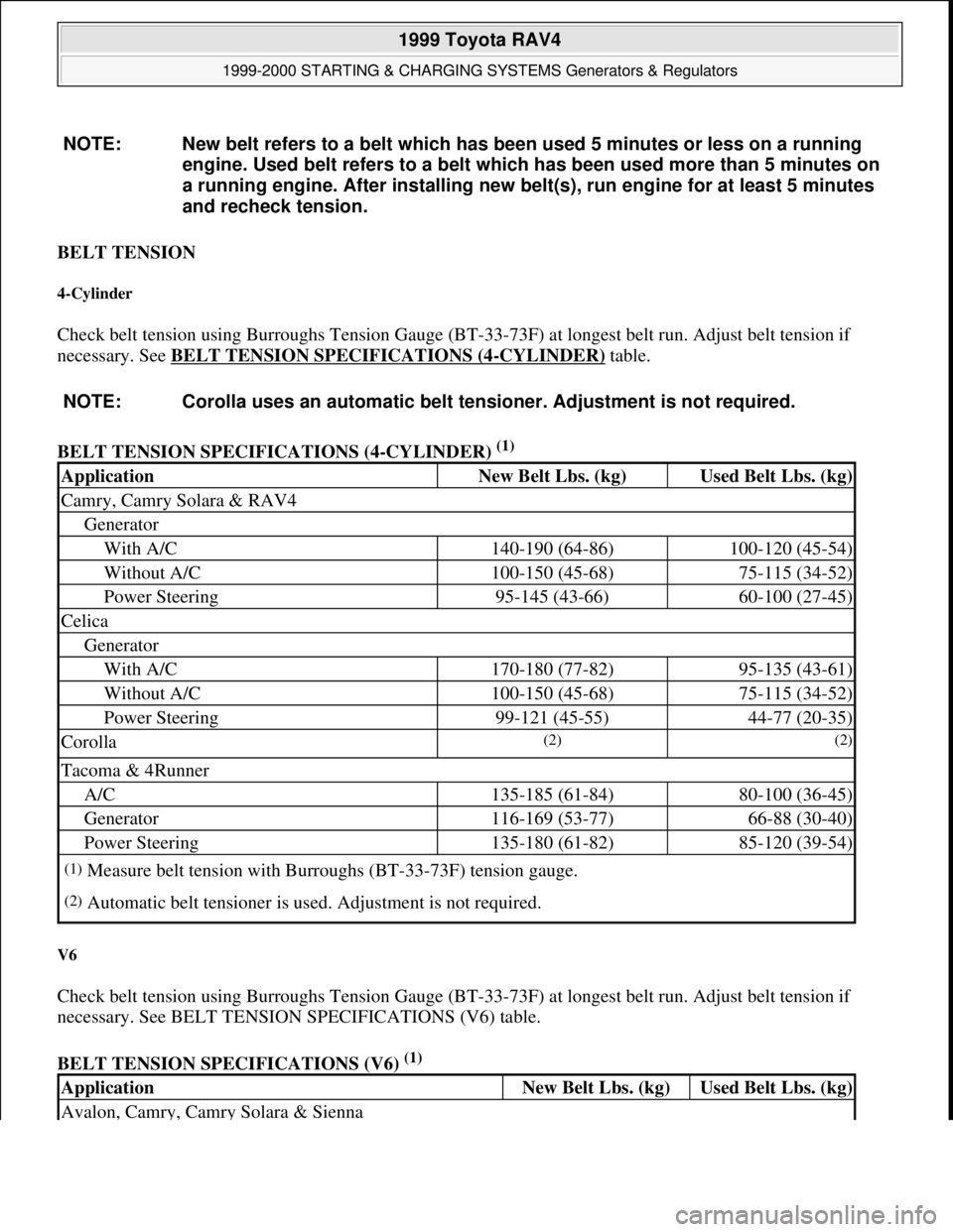
BELT TENSION
4-Cylinder
Check belt tension using Burroughs Tension Gauge (BT-33-73F) at longest belt run. Adjust belt tension if
necessary. See BELT TENSION SPECIFICATIONS (4
-CYLINDER) table.
BELT TENSION SPECIFICATIONS (4-CYLINDER)
(1)
V6
Check belt tension using Burroughs Tension Gauge (BT-33-73F) at longest belt run. Adjust belt tension if
necessary. See BELT TENSION SPECIFICATIONS (V6) table.
BELT TENSION SPECIFICATIONS (V6)
(1) NOTE: New belt refers to a belt which has been used 5 minutes or less on a running
engine. Used belt refers to a belt which has been used more than 5 minutes on
a running engine. After installing new belt(s), run engine for at least 5 minutes
and recheck tension.
NOTE: Corolla uses an automatic belt tensioner. Adjustment is not required.
ApplicationNew Belt Lbs. (kg)Used Belt Lbs. (kg)
Camry, Camry Solara & RAV4
Generator
With A/C140-190 (64-86)100-120 (45-54)
Without A/C100-150 (45-68)75-115 (34-52)
Power Steering95-145 (43-66)60-100 (27-45)
Celica
Generator
With A/C170-180 (77-82)95-135 (43-61)
Without A/C100-150 (45-68)75-115 (34-52)
Power Steering99-121 (45-55)44-77 (20-35)
Corolla(2) (2)
Tacoma & 4Runner
A/C135-185 (61-84)80-100 (36-45)
Generator116-169 (53-77)66-88 (30-40)
Power Steering135-180 (61-82)85-120 (39-54)
(1)Measure belt tension with Burroughs (BT-33-73F) tension gauge.
(2)Automatic belt tensioner is used. Adjustment is not required.
ApplicationNew Belt Lbs. (kg)Used Belt Lbs. (kg)
Avalon, Camry, Camry Solara & Sienna
1999 Toyota RAV4
1999-2000 STARTING & CHARGING SYSTEMS Generators & Regulators
Microsoft
Sunday, November 22, 2009 10:13:07 AMPage 2 © 2005 Mitchell Repair Information Company, LLC.
Page 404 of 1632
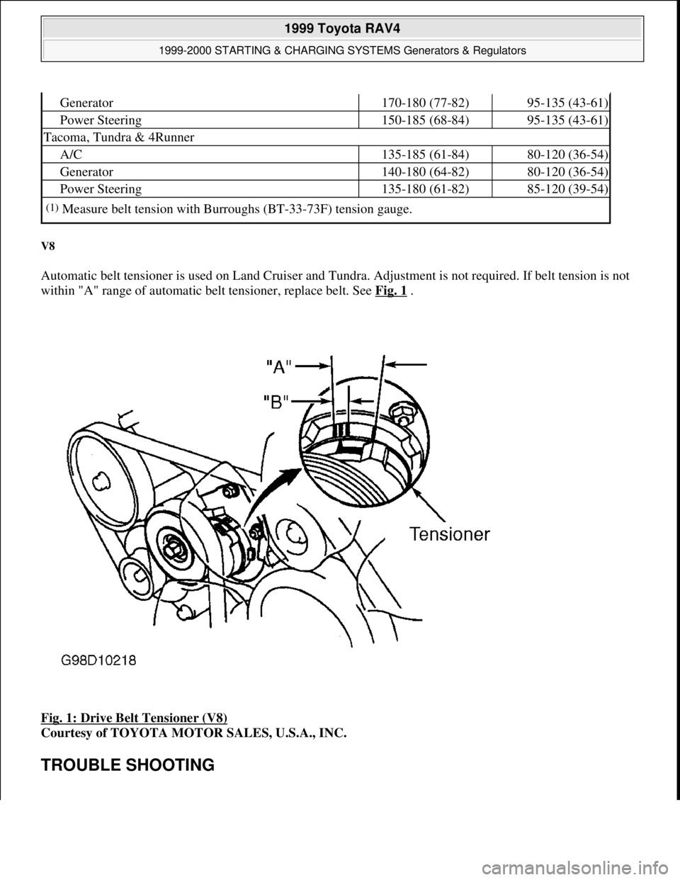
V8
Automatic belt tensioner is used on Land Cruiser and Tundra. Adjustment is not required. If belt tension is not
within "A" range of automatic belt tensioner, replace belt. See Fig. 1
.
Fig. 1: Drive Belt Tensioner (V8)
Courtesy of TOYOTA MOTOR SALES, U.S.A., INC.
TROUBLE SHOOTING
Generator170-180 (77-82)95-135 (43-61)
Power Steering150-185 (68-84)95-135 (43-61)
Tacoma, Tundra & 4Runner
A/C135-185 (61-84)80-120 (36-54)
Generator140-180 (64-82)80-120 (36-54)
Power Steering135-180 (61-82)85-120 (39-54)
(1)Measure belt tension with Burroughs (BT-33-73F) tension gauge.
1999 Toyota RAV4
1999-2000 STARTING & CHARGING SYSTEMS Generators & Regulators
Microsoft
Sunday, November 22, 2009 10:13:07 AMPage 3 © 2005 Mitchell Repair Information Company, LLC.