power steering TOYOTA RAV4 1996 Service Repair Manual
[x] Cancel search | Manufacturer: TOYOTA, Model Year: 1996, Model line: RAV4, Model: TOYOTA RAV4 1996Pages: 1632, PDF Size: 41.64 MB
Page 16 of 1632
1. Disconnect front speed sensor connector. Measure resistance between speed sensor connector terminals.
Resistance should be 1.4-1.8 k/ohms. Measure resistance between ground and each speed sensor
connector terminal. Resistance should be one megohm or more. If resistance is as specified, go to step 3 .
If resistance is not as specified, replace speed sensor.
2. Disconnect rear speed sensor connector. Measure resistance between speed sensor connector terminals.
Resistance should be 1.28-1.48 k/ohms. Measure resistance between ground and each speed sensor
connector terminal. Resistance should be one megohm or more. If resistance is as specified, go to next
step. If resistance is not as specified, replace speed sensor.
3. Check for open or short circuit in wiring harness between affected speed sensor and ABS ECU. See
WIRING DIAGRAMS
. Repair as necessary. If wiring harness is okay, go to next step.
4. Check speed sensor installation. Ensure mounting bolt is tightened to specification. See TORQUE
SPECIFICATIONS . Ensure zero clearance exists between sensor and front steering knuckle or rear axle
carrier. Replace speed sensor if necessary. If speed sensor installation is okay, check speed sensor signal.
See SPEED SENSOR DIAGNOSTICS
under DIAGNOSIS & TESTING. If signal is normal, go to next
step.
5. If oscilloscope is available, check speed sensor signal wave form. Remove ABS ECU. Do not disconnect
electrical connectors. Connect oscilloscope between GND terminal and terminals FR+, FL+, RR+ and
RL+ at ABS ECU connector. See Fig. 3
. Drive vehicle at 19 MPH and observe signal wave form. Signal
should be smooth and consistent without any irregular wave forms. If wave form is smooth and
consistent, replace ABS ECU. If wave form is not smooth and consistent, go to next step.
6. Check speed sensor rotor for missing teeth or damage. Check sensor tip for scratches, damage or foreign
objects. Replace components as necessary. If rotor and sensor are okay, replace ABS ECU.
DTC 37: TIRES OF DIFFERENT SIZE (2WD MODELS ONLY)
DTC Detecting Condition
Detection of the following condition may set DTC 37:
Driving vehicle at speed of more than 12 MPH for more than 20 seconds with one or 2 tires of different
sizes, 3 different times continuously will set DTC 37.
Diagnostic Procedure
Ensure vehicle tires are all the same size and correct size for vehicle. Replace tires as necessary. If tire size is
okay, replace ABS ECU.
DTC 41: LOW BATTERY VOLTAGE
Circuit Description
Circuit is power source for ABS ECU, which includes actuator. If malfunction occurs in power source circuit,
ABS ECU cuts off current to ABS control relay and prohibits ABS control. DEFINITIONS
under DIAGNOSIS & TESTING. For front speed sensor diagnosis,
start at step 1 . For rear speed sensor, start at step 2 .
1999 Toyota RAV4
1999-2000 BRAKES Anti-Lock - RAV4
Microsoft
Sunday, November 22, 2009 10:06:17 AMPage 16 © 2005 Mitchell Repair Information Company, LLC.
Page 26 of 1632
1. Check charging system voltage. Ensure 10-14 volts is present. If charging system voltage is okay, go to
next step. If charging system voltage is not okay, check and repair charging system.
2. Turn ignition switch to ON position. Ensure ABS warning light comes on, then goes out after 3 seconds.
If ABS warning light does not illuminate, check fuse, bulb, and wiring harness. See ABS WARNING
LIGHT under DIAGNOSIS & TESTING. Turn ignition off.
3. Using a jumper wire, jumper terminals Ts and E
1 of DLC1. DLC1 is located in engine compartment on
left side of engine. See Fig. 2
. Ensure ABS warning light blinks 4 times per second. If ABS light does
not blink, go to ABS WARNING LIGHT
under DIAGNOSIS & TESTING. If ABS warning light
blinks, go to next step.
4. Using a floor jack, slowly jack up rear of vehicle. On vehicles with 215/70R16 tires, raise vehicle to a
height of 25.59-27.95" (650-710 mm). On vehicles with 235/60R16 tires, raise vehicle to a height of
26.38-28.74" (670-730 mm). If ABS warning light illuminates at specified height, check deceleration
sensor installation. If installation is okay, replace deceleration sensor. Lower vehicle.
5. Using a floor jack, slowly jack up front of vehicle. On vehicles with 215/70R16 tires, raise vehicle to a
height of 21.20-23.56" (550-610 mm). On vehicles with 235/60R16 tires, raise vehicle to a height of
22.44-24.80" (570-630 mm). If ABS warning light illuminates at specified height, check deceleration
sensor installation. If installation is okay, replace deceleration sensor. Lower vehicle.
6. Drive vehicle straight ahead at speed of 13 MPH or more. Lightly depress brake pedal. Ensure ABS
warning light pattern is normal (light blinks 4 times per second).
7. While driving vehicle straight ahead at speed of 13 MPH or more, moderately depress brake pedal.
Ensure ABS warning light illuminates in a solid pattern (light does not blink) while braking.
8. While driving vehicle straight ahead at speed of 13 MPH or more, firmly depress brake pedal. Ensure
ABS warning light illumination pattern changes from a solid pattern (light does not blink) to a normal
pattern (light blinks 4 times per second), then back to a solid pattern while braking.
9. If ABS warning light does not illuminate as described in steps 6 -8 , check deceleration sensor
installation. If installation is okay, replace deceleration sensor. Stop vehicle and turn ignition off. Remove
jumper wire from DLC1.
REMOVAL & INSTALLATION
ACTUATOR
Removal & Installation
Turn ignition off. Disconnect brakelines attached to actuator. Remove power steering hose retaining bracket
bolt and power steering reservoir. Disconnect actuator electrical connectors. Remove bolts, nuts and washers.
Remove actuator assembly. Remove actuator from actuator bracket. Remove cushions and holders from NOTE: When measuring vehicle height in following steps, measure at center of
lower body of vehicle.
WARNING:Hydraulic system may be under high pressure. Use caution when opening
hydraulic system.
1999 Toyota RAV4
1999-2000 BRAKES Anti-Lock - RAV4
Microsoft
Sunday, November 22, 2009 10:06:17 AMPage 26 © 2005 Mitchell Repair Information Company, LLC.
Page 37 of 1632
The air bag sensor, which deploys air bags, contains a back-up power supply, safing sensor and diagnostic code
memory. Spiral cable (clockspring) maintains a complete circuit to the steering wheel pad.
SYSTEM OPERATION CHECK
Turn ignition switch to ACC or ON position. Air bag warning light in instrument cluster should come on for
about 6 seconds and then go out. If light does not respond as specified, SRS is malfunctioning and needs repair.
See DIAGNOSIS
.
SERVICE PRECAUTIONS
Observe the following precautions when working on SRS:
Before servicing any SRS or steering column component, disable SRS. See DISABLING &
ACTIVATING AIR BAG SYSTEM . Failure to disable system could result in accidental air bag
deployment and personal injury.
When diagnosing SRS, always check for diagnostic codes before disconnecting battery.
After ignition switch is turned to LOCK position and negative battery cable is disconnected, wait at least
90 seconds before working on SRS. SRS is equipped with a back-up power source that may allow air bag
to deploy within 90 seconds of disconnecting negative battery cable.
In a minor collision in which air bags do not deploy, steering wheel pad must be inspected.
NEVER use air bag parts from another vehicle. Replace air bag parts with new parts.
Air bag sensor assembly contains mercury. After replacement, DO NOT destroy the old part. When
scrapping vehicle or replacing air bag sensor assembly, remove air bag sensor assembly and dispose of as
toxic waste.
Never disassemble or repair system components. Replace cracked, dented or otherwise damaged system
components.
Remove air bag sensor if shocks are likely to be applied to the sensor during repairs.
When diagnosing electrical circuits, use a Digital Volt/Ohmmeter (DVOM) with high impedance (10,000
ohms minimum).
Information labels are attached to air bag components. Follow all notices on labels.
After servicing SRS, check air bag warning light to ensure system is functioning properly. See SYSTEM
OPERATION CHECK .
Always wear safety glasses when servicing or handling an air bag.
When placing a live air bag on a bench or other surface, always face air bag and trim cover up, away from
surface. This will reduce motion of module if accidentally deployed.
After deployment, air bag surface may contain deposits of sodium hydroxide which irritates skin. During
clean-up, always wear safety glasses, rubber gloves and long-sleeved shirt. After clean-up, wash hands
using mild soap and water.
When carrying a live air bag module, trim cover must be pointed away from your body to minimize
injury in case of accidental deployment.
If SRS is not fully functional for any reason, vehicle should not be driven until system is repaired and
a
gain becomes operational. DO NOTremove bulbs, modules, sensors or other components or in any way
1996 Toyota 4Runner
AIR BAG RESTRAINT SYSTEM 1996 ACCESSORIES/SAFETY EQUIPMENT Toyota Air Bag Restraint System
Microsoft
Tuesday, August 18, 2009 7:33:32 PMPage 3 © 2005 Mitchell Repair Information Company, LLC.
Page 38 of 1632
disable system from operating normally. If SRS is not functional, park vehicle until it is repaired and
functions properly.
DISABLING & ACTIVATING AIR BAG SYSTEM
DISABLING SYSTEM
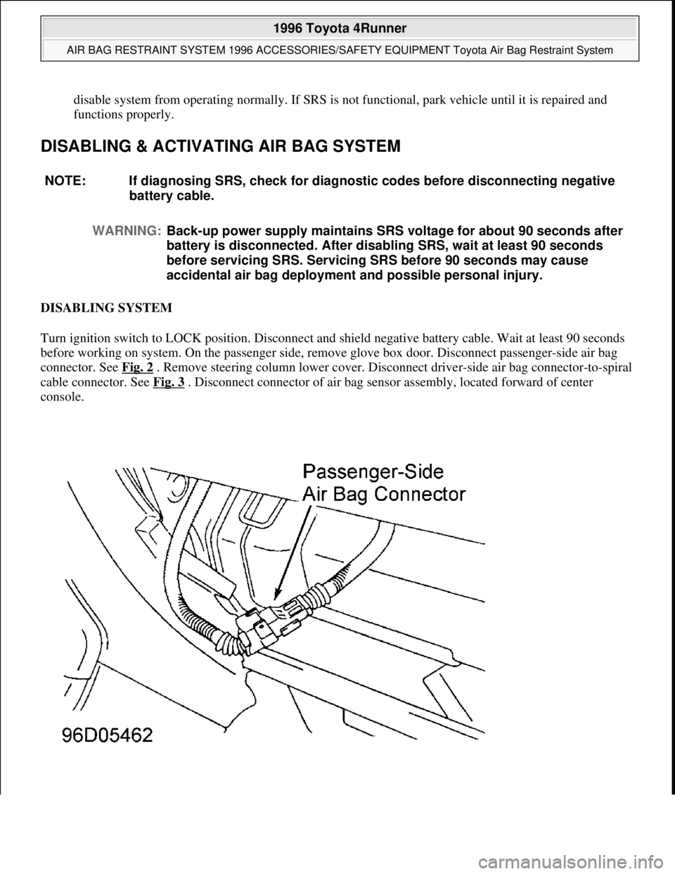
Turn ignition switch to LOCK position. Disconnect and shield negative battery cable. Wait at least 90 seconds
before working on system. On the passenger side, remove glove box door. Disconnect passenger-side air bag
connector. See Fig. 2
. Remove steering column lower cover. Disconnect driver-side air bag connector-to-spiral
cable connector. See Fig. 3
. Disconnect connector of air bag sensor assembly, located forward of center
console. NOTE: If diagnosing SRS, check for diagnostic codes before disconnecting negative
battery cable.
WARNING:Back-up power supply maintains SRS voltage for about 90 seconds after
battery is disconnected. After disabling SRS, wait at least 90 seconds
before servicing SRS. Servicing SRS before 90 seconds may cause
accidental air bag deployment and possible personal injury.
1996 Toyota 4Runner
AIR BAG RESTRAINT SYSTEM 1996 ACCESSORIES/SAFETY EQUIPMENT Toyota Air Bag Restraint System
Microsoft
Tuesday, August 18, 2009 7:33:32 PMPage 4 © 2005 Mitchell Repair Information Company, LLC.
Page 60 of 1632
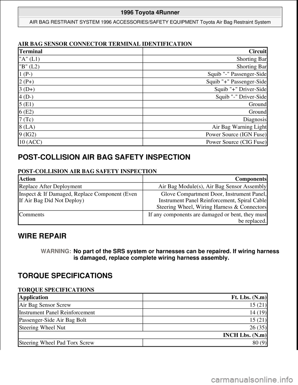
AIR BAG SENSOR CONNECTOR TERMINAL IDENTIFICATION
POST-COLLISION AIR BAG SAFETY INSPECTION
POST-COLLISION AIR BAG SAFETY INSPECTION
WIRE REPAIR
TORQUE SPECIFICATIONS
TORQUE SPECIFICATIONS
TerminalCircuit
"A" (L1)Shorting Bar
"B" (L2)Shorting Bar
1 (P-)Squib "-" Passenger-Side
2 (P+)Squib "+" Passenger-Side
3 (D+)Squib "+" Driver-Side
4 (D-)Squib "-" Driver-Side
5 (E1)Ground
6 (E2)Ground
7 (Tc)Diagnosis
8 (LA)Air Bag Warning Light
9 (IG2)Power Source (IGN Fuse)
10 (ACC)Power Source (CIG Fuse)
ActionComponents
Replace After DeploymentAir Bag Module(s), Air Bag Sensor Assembly
Inspect & If Damaged, Replace Component (Even
If Air Bag Did Not Deploy)Glove Compartment Door, Instrument Panel,
Instrument Panel Reinforcement, Spiral Cable
Steering Wheel, Wiring Harness & Connectors
CommentsIf any components are damaged or bent, they must
be replaced.
WARNING:No part of the SRS system or harnesses can be repaired. If wiring harness
is damaged, replace complete wiring harness assembly.
ApplicationFt. Lbs. (N.m)
Air Bag Sensor Screw15 (21)
Instrument Panel Reinforcement14 (19)
Passenger-Side Air Bag Bolt15 (21)
Steering Wheel Nut26 (35)
INCH Lbs. (N.m)
Steering Wheel Pad Torx Screw80 (9)
1996 Toyota 4Runner
AIR BAG RESTRAINT SYSTEM 1996 ACCESSORIES/SAFETY EQUIPMENT Toyota Air Bag Restraint System
Microsoft
Tuesday, August 18, 2009 7:33:32 PMPage 26 © 2005 Mitchell Repair Information Company, LLC.
Page 65 of 1632
Fig. 1: Locating Restraint System Components
Courtesy of TOYOTA MOTOR SALES, U.S.A., INC.
AIR BAG SENSOR ASSEMBLY
The air bag sensor assembly is located on the floor inside center console box. It consists of an air bag sensor,
safing sensor and diagnosis, ignition control and drive circuits. It receives signals from the air bag sensor and
determines whether air bag system must be deployed or not.
DRIVER-SIDE AIR BAG MODULE
The driver-side air bag and inflator is stored in the steering wheel pad. It contains a squib, igniter charge and gas
generant and inflates the air bag when instructed by air bag sensor assembly. Driver-side air bag module is also
called steering wheel pad.
FRONT AIR BAG SENSOR
The front air bag sensors are mounted inside right and left front side members. When sensor detects an impact
of sufficient force (above a predetermined limit), contacts inside the sensor close, sending a signal to the air bag
sensor assembly.
PASSENGER-SIDE AIR BAG MODULE
The passenger-side air bag and inflator is stored in the instrument panel above glove box. It contains a squib,
igniter charge and gas generant and inflates the air bag when instructed by air bag sensor assembly.
SEAT BELT PRETENSIONER
The seat belt pretensioner system is a component of the front outer seat belt assembly. It contains a squib, gas
generant, wire and piston and operates in the event of a front-end collision.
SPIRAL CABLE
The spiral cable is attached to combination switch and is used as an electrical joint between chassis wiring
harness and driver-side air bag module. Spiral cable is also known as clockspring.
SERVICE PRECAUTIONS
Observe the following precautions when servicing air bag system:
Disable air bag system before servicing any air bag system or steering column component. Failure to do
this could result in accidental air bag deployment and possible personal injury. See DISABLING &
ACTIVATING AIR BAG SYSTEM .
When diagnosing air bag system, always check for diagnostic codes before disconnecting battery.
After turning ignition switch to LOCK position and disconnecting negative battery cable, wait at least 90
seconds before workin
g on air bag system. Air bag system is equipped with a back-up power source that
1999 Toyota RAV4
AIR BAG RESTRAINT SYSTEM 1999 Toyota
Microsoft
Sunday, November 22, 2009 10:33:22 AMPage 2 © 2005 Mitchell Repair Information Company, LLC.
Page 114 of 1632
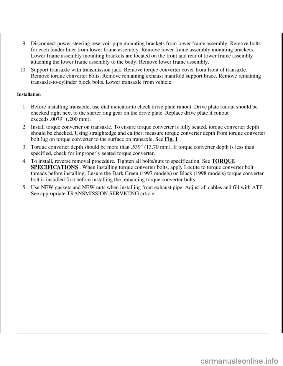
9. Disconnect power steering reservoir pipe mounting brackets from lower frame assembly. Remove bolts
for each fender liner from lower frame assembly. Remove lower frame assembly mounting brackets.
Lower frame assembly mounting brackets are located on the front and rear of lower frame assembly
attaching the lower frame assembly to the body. Remove lower frame assembly.
10. Support transaxle with transmission jack. Remove torque converter cover from front of transaxle.
Remove torque converter bolts. Remove remaining exhaust manifold support brace. Remove remaining
transaxle-to-cylinder block bolts. Lower transaxle from vehicle.
Installation
1. Before installing transaxle, use dial indicator to check drive plate runout. Drive plate runout should be
checked right next to the starter ring gear on the drive plate. Replace drive plate if runout
exceeds .0079" (.200 mm).
2. Install torque converter on transaxle. To ensure torque converter is fully seated, torque converter depth
should be checked. Using straightedge and caliper, measure torque converter depth from torque converter
bolt lug on torque converter to the surface on transaxle. See Fig. 1
.
3. Torque converter depth should be more than .539" (13.70 mm). If torque converter depth is less than
specified, check for improperly seated torque converter.
4. To install, reverse removal procedure. Tighten all bolts/nuts to specification. See TORQUE
SPECIFICATIONS . When installing torque converter bolts, apply Loctite to torque converter bolt
threads before installing. Ensure the Dark Green (1997 models) or Black (1998 models) torque converter
bolt is installed first before installing the remaining torque converter bolts.
5. Use NEW gaskets and NEW nuts when installing front exhaust pipe. Adjust all cables and fill with ATF.
See appropriate TRANSMISSION SERVICING article.
1998 Toyota Avalon XLS
TRANSMISSION SERVICING - A/T 1997-98 TRANSMISSION SERVICING Toyota - Transmission Removal &
Installation
Helpmelearn
November-03-08 10:30:28 AMPage 2 © 2005 Mitchell Repair Information Company, LLC.
Page 115 of 1632
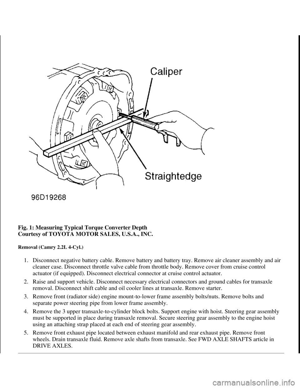
Fig. 1: Measuring Typical Torque Converter Depth
Courtesy of TOYOTA MOTOR SALES, U.S.A., INC.
Removal (Camry 2.2L 4-Cyl.)
1. Disconnect negative battery cable. Remove battery and battery tray. Remove air cleaner assembly and air
cleaner case. Disconnect throttle valve cable from throttle body. Remove cover from cruise control
actuator (if equipped). Disconnect electrical connector at cruise control actuator.
2. Raise and support vehicle. Disconnect necessary electrical connectors and ground cables for transaxle
removal. Disconnect shift cable and oil cooler lines at transaxle. Remove starter.
3. Remove front (radiator side) engine mount-to-lower frame assembly bolts/nuts. Remove bolts and
separate power steering pipe from lower frame assembly.
4. Remove the 3 upper transaxle-to-cylinder block bolts. Support engine with hoist. Steering gear assembly
must be supported in place during transaxle removal. Secure steering gear assembly to the engine hoist
using an attaching strap placed at each end of steering gear assembly.
5. Remove front exhaust pipe located between exhaust manifold and rear exhaust pipe. Remove front
wheels. Drain transaxle fluid. Remove axle shafts from transaxle. See FWD AXLE SHAFTS article in
DRIVE AXLES.
1998 Toyota Avalon XLS
TRANSMISSION SERVICING - A/T 1997-98 TRANSMISSION SERVICING Toyota - Transmission Removal &
Installation
Helpmelearn
November-03-08 10:30:28 AMPage 3 © 2005 Mitchell Repair Information Company, LLC.
Page 134 of 1632
5. Once engine and transaxle are installed, adjust all cables and fill with ATF. See appropriate
TRANSMISSION SERVICING article.
Removal (Sienna)
1. Disconnect negative battery cable. Remove hood. Remove wiper arms. Remove hood-to-cowl top seal.
Remove cowl panel hole cover. Remove clips and left and right side cowl top ventilator louvers.
Disconnect washer hoses. Remove 2 washer nozzles from cowl top ventilator louvers. Remove 11 bolts
and outer front cowl top panel.
2. Remove battery, battery tray, air cleaner assembly and air cleaner case. Disconnect throttle valve cable
from throttle body. Remove cruise control actuator with mounting bracket from the body.
3. Raise and support vehicle. Disconnect necessary electrical connectors and ground cables for transaxle
removal. Remove starter. Disconnect shift cable and oil cooler lines at transaxle. Remove shift cable
clamp bracket from transaxle.
4. Remove front (radiator side) engine mount shock absorber-to-lower frame assembly bolts. Remove front
(radiator side) engine mount-to-lower frame assembly bolts/nuts.
5. Remove front (radiator side) exhaust manifold brace from rear of exhaust manifolds. Brace fits between
rear of exhaust manifold and front of transaxle.
6. Remove the 5 upper transaxle-to-cylinder block bolts. Support engine with hoist. Steering gear assembly
must be supported in place during transaxle removal. Secure steering gear assembly to the engine hoist
using an attaching strap placed at each end of steering gear assembly.
7. Remove front wheels. Remove engine undercover. Remove front exhaust pipe located between exhaust
manifolds and rear exhaust pipe. Drain transaxle fluid. Remove axle shafts from transaxle. See FWD
AXLE SHAFTS article in DRIVE AXLES.
8. Disconnect shift control cable from mounting bracket. Remove rear (firewall side) engine mount-to-lower
frame assembly bolts/nuts. Remove transaxle mount-to-transaxle bolts/nuts at driver's side end of
transaxle.
9. Remove stabilizer bar mount bracket-to-lower frame assembly bolts. Remove steering gear assembly-to-
lower frame assembly bolts/nuts. Support lower frame assembly with floor jack. Lower frame assembly is
located below the engine and transaxle.
10. Disconnect power steering reservoir pipe mounting brackets from lower frame assembly. Remove lower
frame assembly mounting brackets. Lower frame assembly mounting brackets are located on the front
and rear of lower frame assembly attaching the lower frame assembly to the body. Remove lower frame
assembly.
11. Support transaxle with transmission jack. Remove torque converter bracket and cover bolts and nuts from
front of transaxle. Remove torque converter bolts. Remove remaining transaxle-to-cylinder block bolts.
Lower transaxle from vehicle.
Installation
NOTE: Wiper/washer components and output front cowl top panel must be
removed for clearance during transaxle removal and installation.
1998 Toyota Avalon XLS
TRANSMISSION SERVICING - A/T 1997-98 TRANSMISSION SERVICING Toyota - Transmission Removal &
Installation
Helpmelearn
November-03-08 10:30:29 AMPage 22 © 2005 Mitchell Repair Information Company, LLC.
Page 322 of 1632
1999-2000 DRIVE AXLES
AWD & FWD Axle Shafts - RAV4 & RWD Axle Shafts - MR2
DESCRIPTION & OPERATION
On RAV4 models, axle shafts transfer power from transaxle to front wheels (FWD), or front and rear wheels
(AWD). MR2 are a mid-engine, RWD design. Axle shafts transfer power from transaxle to rear wheels. Axle
shaft consists of axle shaft with flexible Constant Velocity (CV) joint at each end. On RAV4 models, front inner
CV joint is splined to transaxle. Rear inner CV joint is bolted to differential. Outer CV joint is splined to front
or rear hub assembly. On MR2 models, rear inner CV joint is splined to transaxle and Outer CV joint is splined
to rear hub assembly.
Inner and outer CV joints are enclosed by a CV joint boot. Boot maintains lubrication in CV joint and prevents
contamination of CV lubricant. Boots must be replaced if cracked, torn or damaged. Inner CV joint can be
repaired without replacing assembly but outer CV joint must be replaced as an assembly.
TROUBLE SHOOTING
REMOVAL & INSTALLATION
FRONT AXLE SHAFTS
Removal (RAV4)
1. Raise and support vehicle. Remove front wheel. Remove engine undercover. Drain gear oil from
transaxle into proper container. Remove ABS speed sensor (if equipped). Remove cotter pin and lock cap.
See Fig. 1
or Fig. 2 . Apply brakes, and remove axle shaft nut from end of axle shaft. Release brakes.
2. Remove cotter pin and nut from tie rod end. Using Tie Rod End Remover (SST 09610-20012), disconnect
tie rod end from steering knuckle. Disconnect stabilizer bar link from lower suspension arm. Remove bolt
and 2 nuts, and separate lower ball joint from suspension arm.
3. Using a plastic hammer, tap axle shaft from hub. Pull steering knuckle outward, and disconnect axle shaft
from steering knuckle.
4. To remove axle shaft (except left side on AWD), use a brass drift and hammer and tap on inner joint to
separate from transaxle. Slide axle shaft toward steering knuckle until free of transaxle assembly. NOTE: See DRIVE AXLE NOISE DIAGNOSIS article in GENERAL INFORMATION.
NOTE: DO NOT damage oil seal, axle shaft boots or Anti-Lock Brake System (ABS)
speed sensor rotor when removing axle shaft.
NOTE: On FWD vehicles, removal of right-side axle shaft requires disassembly of
center bearing axle support. See Fig. 3
or Fig. 4 .
1999 Toyota RAV4
1999-2000 DRIVE AXLES AWD & FWD Axle Shafts - RAV4 & RWD Axle Shafts - MR2
1999 Toyota RAV4
1999-2000 DRIVE AXLES AWD & FWD Axle Shafts - RAV4 & RWD Axle Shafts - MR2
Microsoft
Sunday, November 22, 2009 10:08:21 AMPage 1 © 2005 Mitchell Repair Information Company, LLC.
Microsoft
Sunday, November 22, 2009 10:08:25 AMPage 1 © 2005 Mitchell Repair Information Company, LLC.