tow bar TOYOTA RAV4 1996 Service Repair Manual
[x] Cancel search | Manufacturer: TOYOTA, Model Year: 1996, Model line: RAV4, Model: TOYOTA RAV4 1996Pages: 1632, PDF Size: 41.64 MB
Page 233 of 1632
case. Using A/T Tool Set (09350-32014) and arbor press, remove bearing inner race. Using Bearing
Replacer (09316-60010) and arbor press, install NEW ring gear mounting right case bearing.
9. Use hammer and screwdriver to remove oil seal from ring gear mounting left case. Remove oil baffle
from left bearing retainer. Use hammer and brass bar to drive out outer race and adjusting shim from left
bearing retainer. Place adjusting shim into left bearing retainer. Use either original shim or shim with
thickness of .0945" (2.400 mm). Use A/T Tool Set (09350-32014) and arbor press to install outer race
and shim. Install oil baffle and oil seal after adjusting differential side bearing preload. See
TRANSAXLE REASSEMBLY
.
Reassembly
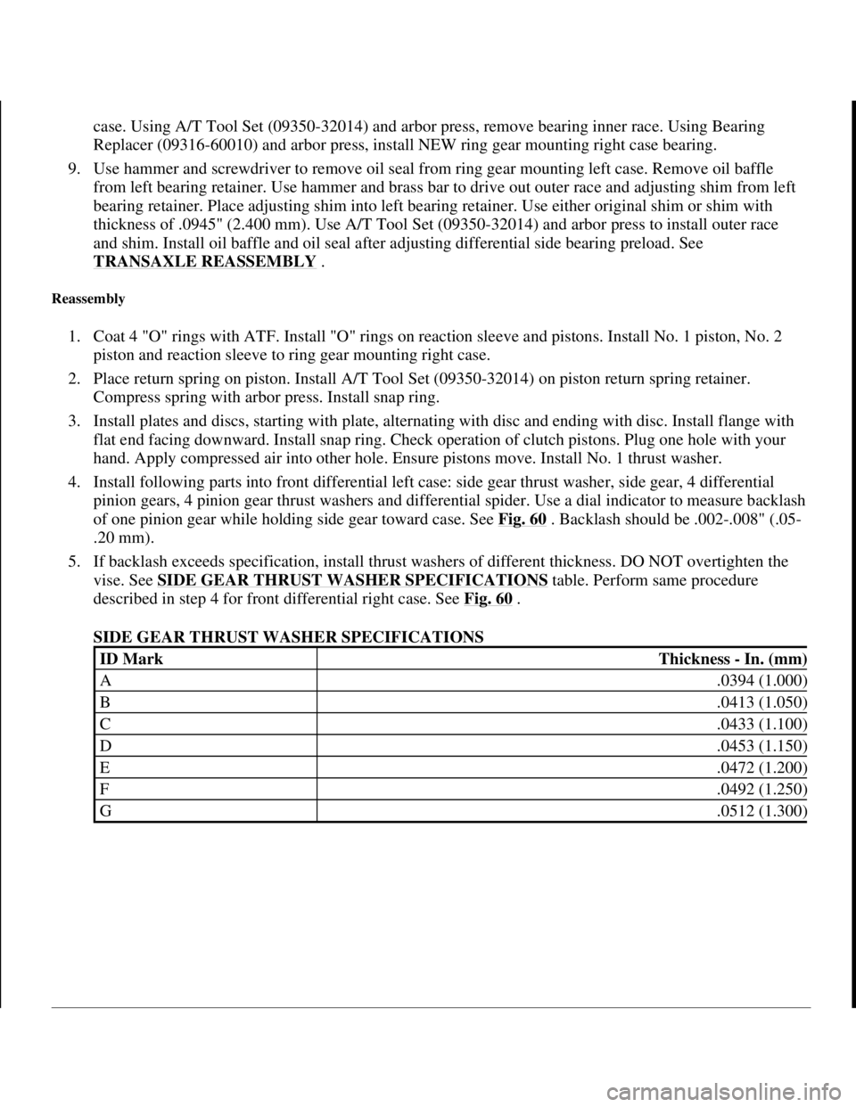
1. Coat 4 "O" rings with ATF. Install "O" rings on reaction sleeve and pistons. Install No. 1 piston, No. 2
piston and reaction sleeve to ring gear mounting right case.
2. Place return spring on piston. Install A/T Tool Set (09350-32014) on piston return spring retainer.
Compress spring with arbor press. Install snap ring.
3. Install plates and discs, starting with plate, alternating with disc and ending with disc. Install flange with
flat end facing downward. Install snap ring. Check operation of clutch pistons. Plug one hole with your
hand. Apply compressed air into other hole. Ensure pistons move. Install No. 1 thrust washer.
4. Install following parts into front differential left case: side gear thrust washer, side gear, 4 differential
pinion gears, 4 pinion gear thrust washers and differential spider. Use a dial indicator to measure backlash
of one pinion gear while holding side gear toward case. See Fig. 60
. Backlash should be .002-.008" (.05-
.20 mm).
5. If backlash exceeds specification, install thrust washers of different thickness. DO NOT overtighten the
vise. See SIDE GEAR THRUST WASHER SPECIFICATIONS
table. Perform same procedure
described in step 4 for front differential right case. See Fig. 60
.
SIDE GEAR THRUST WASHER SPECIFICATIONS
ID MarkThickness - In. (mm)
A.0394 (1.000)
B.0413 (1.050)
C.0433 (1.100)
D.0453 (1.150)
E.0472 (1.200)
F.0492 (1.250)
G.0512 (1.300)
1998 Toyota Avalon XLS
1997-99 AUTOMATIC TRANSMISSIONS Toyota A-540E, A-540H & A-541E Overhaul
Helpmelearn
November-03-08 10:28:19 AMPage 79 © 2005 Mitchell Repair Information Company, LLC.
Page 322 of 1632
1999-2000 DRIVE AXLES
AWD & FWD Axle Shafts - RAV4 & RWD Axle Shafts - MR2
DESCRIPTION & OPERATION
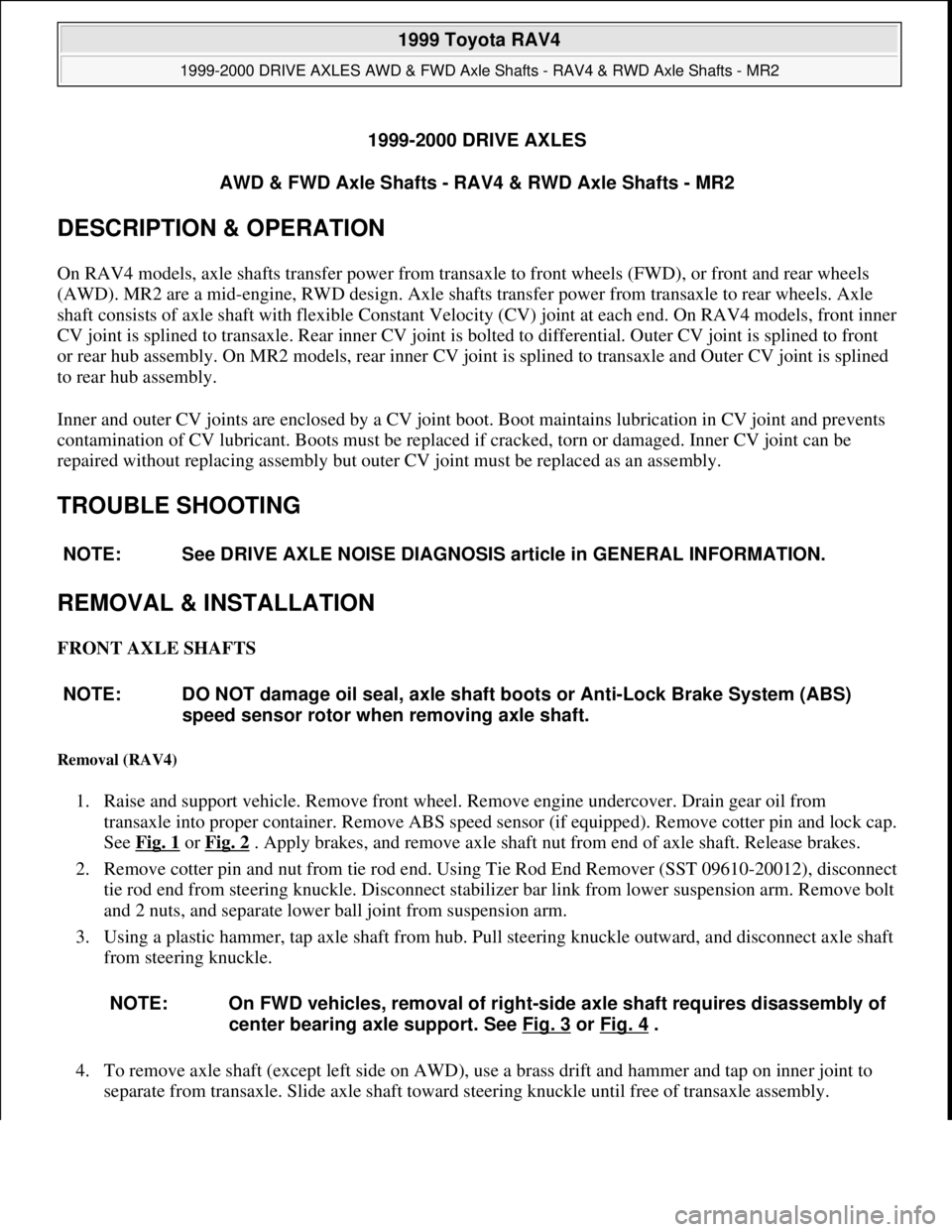
On RAV4 models, axle shafts transfer power from transaxle to front wheels (FWD), or front and rear wheels
(AWD). MR2 are a mid-engine, RWD design. Axle shafts transfer power from transaxle to rear wheels. Axle
shaft consists of axle shaft with flexible Constant Velocity (CV) joint at each end. On RAV4 models, front inner
CV joint is splined to transaxle. Rear inner CV joint is bolted to differential. Outer CV joint is splined to front
or rear hub assembly. On MR2 models, rear inner CV joint is splined to transaxle and Outer CV joint is splined
to rear hub assembly.
Inner and outer CV joints are enclosed by a CV joint boot. Boot maintains lubrication in CV joint and prevents
contamination of CV lubricant. Boots must be replaced if cracked, torn or damaged. Inner CV joint can be
repaired without replacing assembly but outer CV joint must be replaced as an assembly.
TROUBLE SHOOTING
REMOVAL & INSTALLATION
FRONT AXLE SHAFTS
Removal (RAV4)
1. Raise and support vehicle. Remove front wheel. Remove engine undercover. Drain gear oil from
transaxle into proper container. Remove ABS speed sensor (if equipped). Remove cotter pin and lock cap.
See Fig. 1
or Fig. 2 . Apply brakes, and remove axle shaft nut from end of axle shaft. Release brakes.
2. Remove cotter pin and nut from tie rod end. Using Tie Rod End Remover (SST 09610-20012), disconnect
tie rod end from steering knuckle. Disconnect stabilizer bar link from lower suspension arm. Remove bolt
and 2 nuts, and separate lower ball joint from suspension arm.
3. Using a plastic hammer, tap axle shaft from hub. Pull steering knuckle outward, and disconnect axle shaft
from steering knuckle.
4. To remove axle shaft (except left side on AWD), use a brass drift and hammer and tap on inner joint to
separate from transaxle. Slide axle shaft toward steering knuckle until free of transaxle assembly. NOTE: See DRIVE AXLE NOISE DIAGNOSIS article in GENERAL INFORMATION.
NOTE: DO NOT damage oil seal, axle shaft boots or Anti-Lock Brake System (ABS)
speed sensor rotor when removing axle shaft.
NOTE: On FWD vehicles, removal of right-side axle shaft requires disassembly of
center bearing axle support. See Fig. 3
or Fig. 4 .
1999 Toyota RAV4
1999-2000 DRIVE AXLES AWD & FWD Axle Shafts - RAV4 & RWD Axle Shafts - MR2
1999 Toyota RAV4
1999-2000 DRIVE AXLES AWD & FWD Axle Shafts - RAV4 & RWD Axle Shafts - MR2
Microsoft
Sunday, November 22, 2009 10:08:21 AMPage 1 © 2005 Mitchell Repair Information Company, LLC.
Microsoft
Sunday, November 22, 2009 10:08:25 AMPage 1 © 2005 Mitchell Repair Information Company, LLC.
Page 323 of 1632
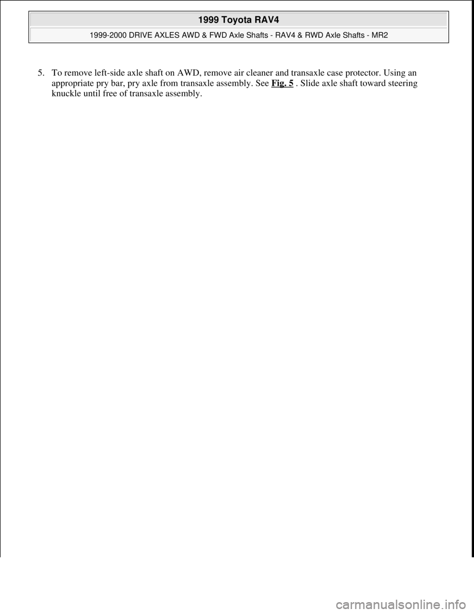
5. To remove left-side axle shaft on AWD, remove air cleaner and transaxle case protector. Using an
appropriate pry bar, pry axle from transaxle assembly. See Fig. 5
. Slide axle shaft toward steering
knuckle until free of transaxle assembl
y.
1999 Toyota RAV4
1999-2000 DRIVE AXLES AWD & FWD Axle Shafts - RAV4 & RWD Axle Shafts - MR2
Microsoft
Sunday, November 22, 2009 10:08:21 AMPage 2 © 2005 Mitchell Repair Information Company, LLC.
Page 612 of 1632
procedure.
2. Apply gear oil to NEW companion flange nut threads. Torque nut to specification. See TORQUE
SPECIFICATIONS . Adjust drive pinion preload. See AXLE ASSEMBLY SPECIFICATIONS . Fill
differential. See LUBRICATION
.
DIFFERENTIAL ASSEMBLY
Removal & Installation
1. Remove drive shaft. See DRIVE SHAFT . Remove rear drive axles. See AWD, FWD & RWD AXLE
SHAFTS - MR2 & RAV4 article in DRIVE AXLES.
2. Support differential with jack. Remove 2 rear mounting bolts. Remove 2 front mounting bolts. Remove
differential. Remove rear mount cushion from differential.
3. To install, reverse removal procedure. Fill differential.
OVERHAUL
REAR DRIVE AXLE
Disassembly
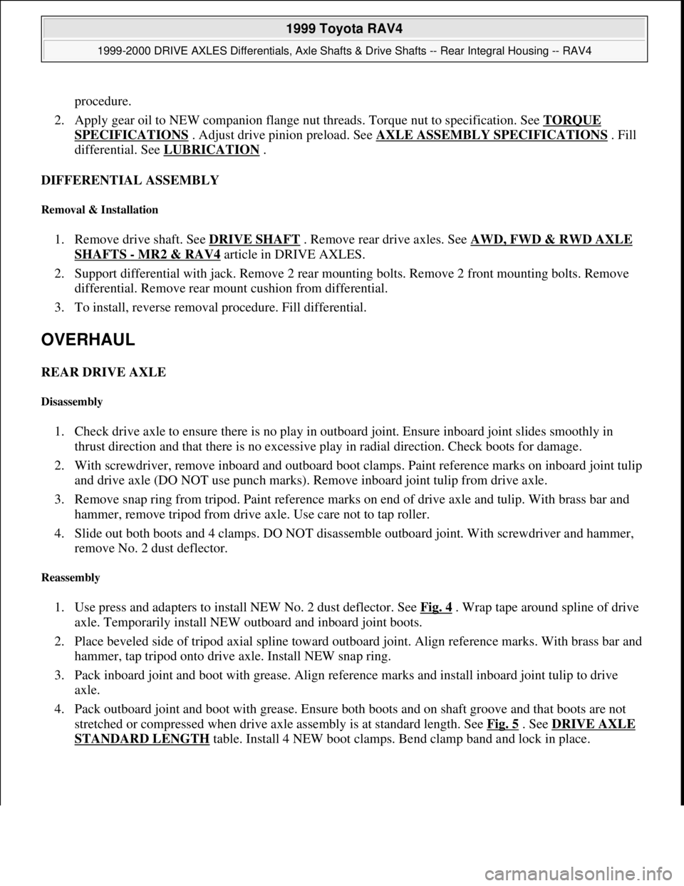
1. Check drive axle to ensure there is no play in outboard joint. Ensure inboard joint slides smoothly in
thrust direction and that there is no excessive play in radial direction. Check boots for damage.
2. With screwdriver, remove inboard and outboard boot clamps. Paint reference marks on inboard joint tulip
and drive axle (DO NOT use punch marks). Remove inboard joint tulip from drive axle.
3. Remove snap ring from tripod. Paint reference marks on end of drive axle and tulip. With brass bar and
hammer, remove tripod from drive axle. Use care not to tap roller.
4. Slide out both boots and 4 clamps. DO NOT disassemble outboard joint. With screwdriver and hammer,
remove No. 2 dust deflector.
Reassembly
1. Use press and adapters to install NEW No. 2 dust deflector. See Fig. 4 . Wrap tape around spline of drive
axle. Temporarily install NEW outboard and inboard joint boots.
2. Place beveled side of tripod axial spline toward outboard joint. Align reference marks. With brass bar and
hammer, tap tripod onto drive axle. Install NEW snap ring.
3. Pack inboard joint and boot with grease. Align reference marks and install inboard joint tulip to drive
axle.
4. Pack outboard joint and boot with grease. Ensure both boots and on shaft groove and that boots are not
stretched or compressed when drive axle assembly is at standard length. See Fig. 5
. See DRIVE AXLE
STANDARD LENGTH table. Install 4 NEW boot clamps. Bend clamp band and lock in place.
1999 Toyota RAV4
1999-2000 DRIVE AXLES Differentials, Axle Shafts & Drive Shafts -- Rear Integral Housing -- RAV4
Microsoft
Sunday, November 22, 2009 10:09:38 AMPage 7 © 2005 Mitchell Repair Information Company, LLC.
Page 836 of 1632
Fig. 12: Exploded View Of Lower Control Arm & Related Components (RAV4)
Courtesy of TOYOTA MOTOR SALES, U.S.A., INC.
BALL JOINTS
Removal & Installation
1. Remove steering knuckle with axle hub. See FRONT AXLE HUB & WHEEL BEARING . Using
screwdriver, pry off dust cover. Remove cotter pin and nut. On all models except Echo, use ball joint
removal tool to remove lower ball joint from axle hub assembly. On Echo, lower control arm must be
removed and replaced to remove ball joint.
2. To install, reverse removal procedure. Check ball joint turning torque. See BALL JOINT CHECKING
under ADJUSTMENTS & INSPECTION. Install NEW cotter pin and NEW dust cover.
STABILIZER BAR
Removal & Installation
1. Remove both front wheels. Remove 4 nuts and remove both stabilizer bar links (2 nuts at each end). On
Echo, remove 2 nuts, 5 retainers, 4 cushions and stabilizer bar link. On Echo and Sienna, disconnect both
tie rod ends from steering knuckles. On all models, remove left and right stabilizer bar brackets and
bushings.
2. On Corolla, remove suspension brace. See Fig. 10
. On Sienna, remove power steering gear mounting
bolts and nuts. See Fig. 13
. On 2000 Celica, remove front suspension member with lower suspension
arm. Remove 2 bolts, bracket and bushing. Install bushing, with cut out facing toward rear, on outside of
paint line on stabilizer bar.
3. On Echo, remove clip and nut, and disconnect steering knuckle. Remove hood, and attach engine sling to
engine hangers. Remove bolt and 2 nuts, and disconnect rear engine mount. Disconnect sliding yoke and
pressure feed and return tubes. Remove bolt, and disconnect tube clamp. Support suspension member
with transmission jack. Remove 4 bolts and lower suspension member. Remove 4 bolts, 2 brackets and
bushings. On all models, remove stabilizer bar. On Avalon, Camry, Camry Solara, Celica and Sienna,
remove stabilizer bar from left side of vehicle. See Fig. 4
.
4. To install, reverse removal procedure. On Sienna, install stabilizer bar with White colored side on right
side and stabilizer bar link with Green colored side on left side. Tighten all bolts and nuts to specification.
See TORQUE SPECIFICATIONS
.
1999 Toyota RAV4
1999-2000 SUSPENSION Front - Avalon, Camry, Camry Solara, Celica, Corolla, Echo, RAV4 & Sienna
Microsoft
Sunday, November 22, 2009 10:36:34 AMPage 18 © 2005 Mitchell Repair Information Company, LLC.