strut TOYOTA RAV4 1996 Service Repair Manual
[x] Cancel search | Manufacturer: TOYOTA, Model Year: 1996, Model line: RAV4, Model: TOYOTA RAV4 1996Pages: 1632, PDF Size: 41.64 MB
Page 29 of 1632
Fig. 11: Exploded View of ABS Actuator
Courtesy of TOYOTA MOTOR SALES, U.S.A., INC.
ABS ECU
Removal & Installation
Ensure ignition is off. Disconnect negative battery cable. Access ABS ECU, located at right side of passenger
compartment. See Fig. 1
. Disconnect ABS ECU connectors. Remove ABS ECU from vehicle. To install,
reverse removal procedure.
FRONT SENSOR ROTOR
Removal & Installation
Front sensor is part of front hub. For removal and installation of front hub, see AXLE SHAFTS - RAV4 article
in DRIVE AXLES.
REAR SENSOR ROTOR
Removal & Installation
Rear sensor rotor is pressed onto axle shaft. For axle shaft removal and installation procedure, see AXLE
SHAFTS - RAV4 article in DRIVE AXLES.
FRONT WHEEL SPEED SENSORS
Removal & Installation
1. Raise and support front of vehicle. Remove front wheel. Remove inner fender panel. Disconnect wheel
speed sensor connector. Remove clamp bolts holding sensor harness to body, strut assembly and steering
knuckle.
2. Remove wheel speed sensor mounting bolt. Remove wheel speed sensor from steering knuckle. To
install, reverse removal procedure. Ensure wheel speed sensor is flat against knuckle when bolt is
tightened. Tighten wheel speed sensor mounting bolt to specification. See TORQUE
SPECIFICATIONS .
REAR WHEEL SPEED SENSORS
Removal & Installation
1. Remove rear seat cushion and side trim panel. Raise and support vehicle. Remove wheel. Unplug wheel
speed sensor connector and remove wire harness from grommet. Disconnect parking brake cable from
suspension arm. Remove clamp bolts holding sensor wiring harness to body and suspension arm.
2. Remove wheel speed sensor. To install, reverse removal procedure. Ensure wheel speed sensor is flat NOTE: Front hub must be removed to service sensor rotor.
1999 Toyota RAV4
1999-2000 BRAKES Anti-Lock - RAV4
Microsoft
Sunday, November 22, 2009 10:06:17 AMPage 29 © 2005 Mitchell Repair Information Company, LLC.
Page 84 of 1632
Using Diagnosis Check Wire
1. Turn ignition switch to ACC or ON position. Wait about 20 seconds. Using Diagnosis Check Wiring
(09843-18020), connect terminals Tc and E1 of Data Link Connector (DLC1). See Fig. 14
. DLC1 is
located forward of right (passenger-side) front strut tower.
2. If AIR BAG warning light flashes 2 times per second, system is normal (normal code). If AIR BAG
warning light does not flash Diagnostic Trouble Codes (DTCs) or flashes DTCs without DLC1
connection, proceed to DTCS NOT DISPLAYED
under DIAGNOSTIC TESTS or DTCS
CONTINUOUSLY DISPLAYED under DIAGNOSTIC TESTS. If AIR BAG warning light is on
continuously and DTC is normal (flashes 2 times per second), source voltage is low. Go to SOURCE
VOLTAGE DROP under DIAGNOSTIC TESTS.
3. If AIR BAG warning light flashes, count number of flashes to determine DTCs that are set. For example,
DTC 12 is: FLASH, 1.5-second pause, FLASH, FLASH. If more than one DTC is displayed, a 2.5-
second pause will occur between each DTC. Lowest numbered DTC will be displayed first, followed by
next higher number DTC until all DTCs have been displayed.
4. After all DTCs are displayed, a 4-second pause will occur, and DTC display will be repeated. See
appropriate DTC under DIAGNOSTIC TESTS. After repairing, clear DTCs. See CLEARING CODES
.
Using Toyota Hand-Held Tester
Install Toyota hand-held tester to DLC1 or DLC3. DLC1 is located forward of right (passenger-side) front strut
tower. See Fig. 14
. DLC3 is located under left side of instrument panel, to right of steering column. Read DTC
by following prompts on tester. See tester operator's manual for instructions. NOTE: If DTCs other than those listed under DIAGNOSTIC TESTS
are displayed,
replace the air bag sensor assembly. If the air bag warning light does not
function as described, proceed to appropriate test under DIAGNOSTIC TESTS
.
1999 Toyota RAV4
AIR BAG RESTRAINT SYSTEM 1999 Toyota
Microsoft
Sunday, November 22, 2009 10:33:23 AMPage 21 © 2005 Mitchell Repair Information Company, LLC.
Page 332 of 1632
1. To install, reverse removal procedure. Before installing axle shafts, install NEW snap ring on end of axle
shaft (except right side). Coat axle shaft seals in transaxle with grease. Coat axle shaft splines and sliding
surfaces with Dexron-II. Position snap ring on end of axle shaft, with opening facing downward.
2. Install axle shaft by lightly tapping axle shaft into transaxle. Ensure axle shaft will move inward and
outward approximately .079-.120" (2.00-3.00 mm), and cannot be pulled from transaxle.
3. To install remaining components, reverse removal procedure. Tighten fasteners to specification. See
TORQUE SPECIFICATIONS
. Fill transaxle with 75W-90 gear oil with API GL-3, GL-4 or GL-5
rating.
REAR AXLE SHAFTS
Removal (MR2)
1. Raise and support vehicle. Remove rear wheels. Remove engine undercovers. Drain differential oil into
proper container. Unstake drive shaft lock nut. Apply brakes and remove nut. Remove bolt and brake flex
hose bracket from shock absorber. Loosen 2 lower shock absorber bolts and nuts.
2. Remove mounting bolts/nuts and disconnect strut rod from axle carrier. Remove mounting bolts/nuts
from No. 1 lower suspension arm. Remove nut and No. 2 lower suspension arm. Remove 2 lower shock
absorber bolts and nuts. See Fig. 8
. Using plastic hammer, remove drive shaft from axle hub. DO NOT
damage oil seal, boots or dust seal. NOTE: DO NOT damage oil seal, axle shaft boots or Anti-Lock Brake System (ABS)
speed sensor rotor when removing axle shaft.
1999 Toyota RAV4
1999-2000 DRIVE AXLES AWD & FWD Axle Shafts - RAV4 & RWD Axle Shafts - MR2
Microsoft
Sunday, November 22, 2009 10:08:21 AMPage 11 © 2005 Mitchell Repair Information Company, LLC.
Page 339 of 1632
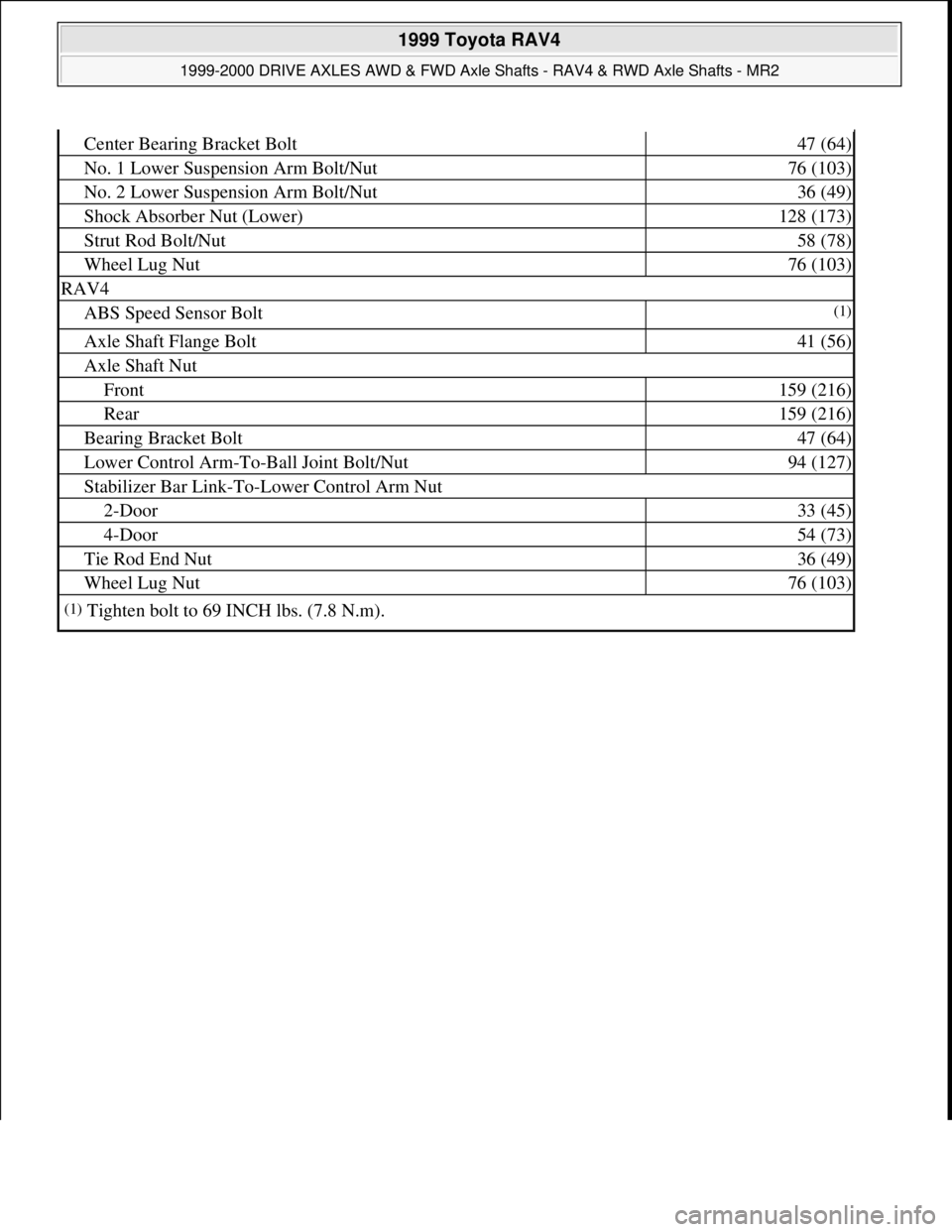
Center Bearing Bracket Bolt47 (64)
No. 1 Lower Suspension Arm Bolt/Nut76 (103)
No. 2 Lower Suspension Arm Bolt/Nut36 (49)
Shock Absorber Nut (Lower)128 (173)
Strut Rod Bolt/Nut58 (78)
Wheel Lug Nut76 (103)
RAV4
ABS Speed Sensor Bolt(1)
Axle Shaft Flange Bolt41 (56)
Axle Shaft Nut
Front159 (216)
Rear159 (216)
Bearing Bracket Bolt47 (64)
Lower Control Arm-To-Ball Joint Bolt/Nut94 (127)
Stabilizer Bar Link-To-Lower Control Arm Nut
2-Door33 (45)
4-Door54 (73)
Tie Rod End Nut36 (49)
Wheel Lug Nut76 (103)
(1)Tighten bolt to 69 INCH lbs. (7.8 N.m).
1999 Toyota RAV4
1999-2000 DRIVE AXLES AWD & FWD Axle Shafts - RAV4 & RWD Axle Shafts - MR2
Microsoft
Sunday, November 22, 2009 10:08:21 AMPage 18 © 2005 Mitchell Repair Information Company, LLC.
Page 369 of 1632
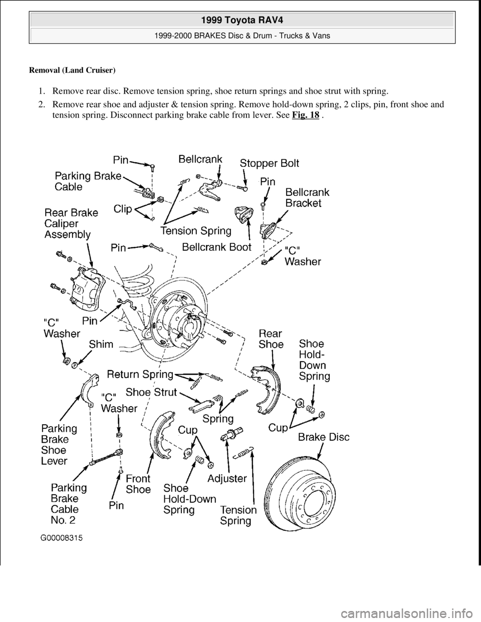
Removal (Land Cruiser)
1. Remove rear disc. Remove tension spring, shoe return springs and shoe strut with spring.
2. Remove rear shoe and adjuster & tension spring. Remove hold-down spring, 2 clips, pin, front shoe and
tension spring. Disconnect parking brake cable from lever. See Fig. 18
.
1999 Toyota RAV4
1999-2000 BRAKES Disc & Drum - Trucks & Vans
Microsoft
Sunday, November 22, 2009 10:07:28 AMPage 30 © 2005 Mitchell Repair Information Company, LLC.
Page 621 of 1632
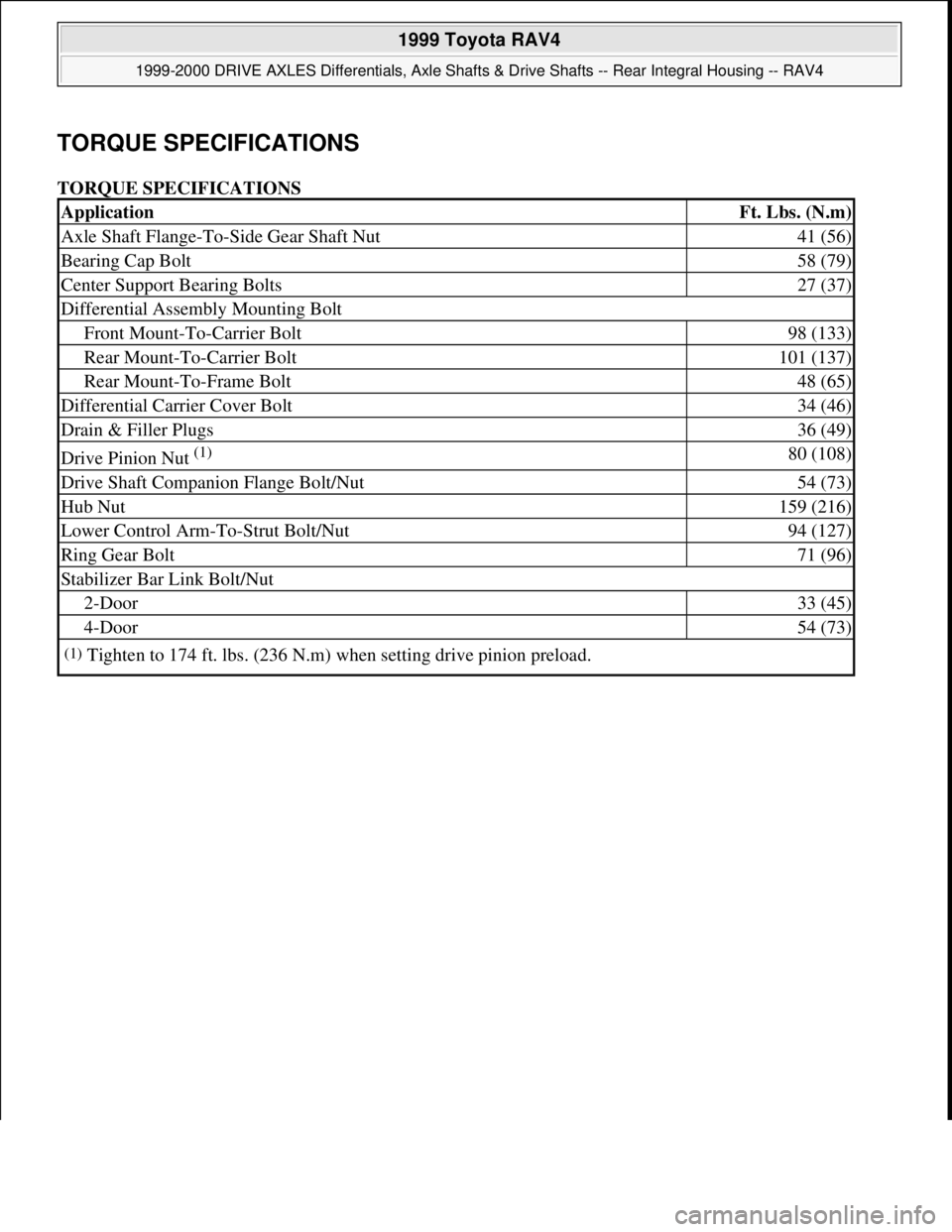
TORQUE SPECIFICATIONS
TORQUE SPECIFICATIONS
ApplicationFt. Lbs. (N.m)
Axle Shaft Flange-To-Side Gear Shaft Nut41 (56)
Bearing Cap Bolt58 (79)
Center Support Bearing Bolts27 (37)
Differential Assembly Mounting Bolt
Front Mount-To-Carrier Bolt98 (133)
Rear Mount-To-Carrier Bolt101 (137)
Rear Mount-To-Frame Bolt48 (65)
Differential Carrier Cover Bolt34 (46)
Drain & Filler Plugs36 (49)
Drive Pinion Nut (1) 80 (108)
Drive Shaft Companion Flange Bolt/Nut54 (73)
Hub Nut159 (216)
Lower Control Arm-To-Strut Bolt/Nut94 (127)
Ring Gear Bolt71 (96)
Stabilizer Bar Link Bolt/Nut
2-Door33 (45)
4-Door54 (73)
(1)Tighten to 174 ft. lbs. (236 N.m) when setting drive pinion preload.
1999 Toyota RAV4
1999-2000 DRIVE AXLES Differentials, Axle Shafts & Drive Shafts -- Rear Integral Housing -- RAV4
Microsoft
Sunday, November 22, 2009 10:09:38 AMPage 16 © 2005 Mitchell Repair Information Company, LLC.
Page 674 of 1632
1999 TOYOTA
RAV4
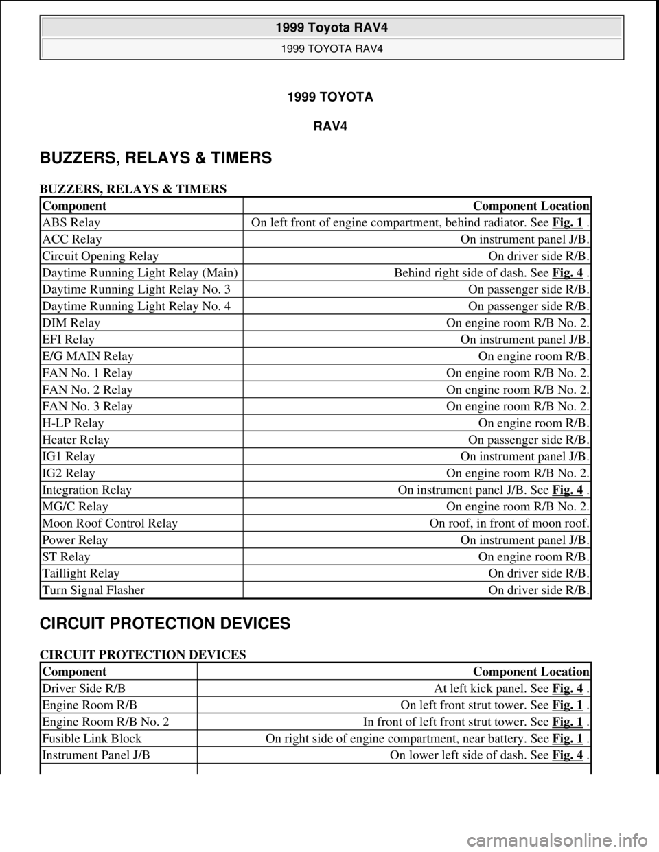
BUZZERS, RELAYS & TIMERS
BUZZERS, RELAYS & TIMERS
CIRCUIT PROTECTION DEVICES
CIRCUIT PROTECTION DEVICES
ComponentComponent Location
ABS RelayOn left front of engine compartment, behind radiator. See Fig. 1 .
ACC RelayOn instrument panel J/B.
Circuit Opening RelayOn driver side R/B.
Daytime Running Light Relay (Main)Behind right side of dash. See Fig. 4 .
Daytime Running Light Relay No. 3On passenger side R/B.
Daytime Running Light Relay No. 4On passenger side R/B.
DIM RelayOn engine room R/B No. 2.
EFI RelayOn instrument panel J/B.
E/G MAIN RelayOn engine room R/B.
FAN No. 1 RelayOn engine room R/B No. 2.
FAN No. 2 RelayOn engine room R/B No. 2.
FAN No. 3 RelayOn engine room R/B No. 2.
H-LP RelayOn engine room R/B.
Heater RelayOn passenger side R/B.
IG1 RelayOn instrument panel J/B.
IG2 RelayOn engine room R/B No. 2.
Integration RelayOn instrument panel J/B. See Fig. 4 .
MG/C RelayOn engine room R/B No. 2.
Moon Roof Control RelayOn roof, in front of moon roof.
Power RelayOn instrument panel J/B.
ST RelayOn engine room R/B.
Taillight RelayOn driver side R/B.
Turn Signal FlasherOn driver side R/B.
ComponentComponent Location
Driver Side R/BAt left kick panel. See Fig. 4 .
Engine Room R/BOn left front strut tower. See Fig. 1 .
Engine Room R/B No. 2In front of left front strut tower. See Fig. 1 .
Fusible Link BlockOn right side of engine compartment, near battery. See Fig. 1 .
Instrument Panel J/BOn lower left side of dash. See Fig. 4 .
1999 Toyota RAV4
1999 TOYOTA RAV4
1999 Toyota RAV4
1999 TOYOTA RAV4
Microsoft
Sunday, November 22, 2009 10:17:32 AMPage 1 © 2005 Mitchell Repair Information Company, LLC.
Microsoft
Sunday, November 22, 2009 10:17:35 AMPage 1 © 2005 Mitchell Repair Information Company, LLC.
Page 675 of 1632
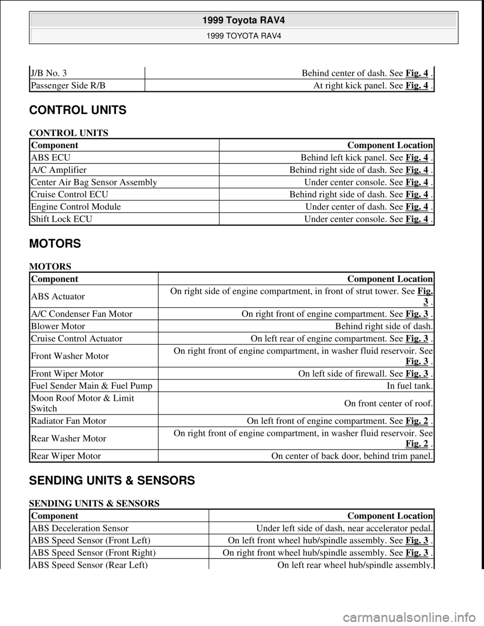
CONTROL UNITS
CONTROL UNITS
MOTORS
MOTORS
SENDING UNITS & SENSORS
SENDING UNITS & SENSORS
J/B No. 3Behind center of dash. See Fig. 4 .
Passenger Side R/BAt right kick panel. See Fig. 4 .
ComponentComponent Location
ABS ECUBehind left kick panel. See Fig. 4 .
A/C AmplifierBehind right side of dash. See Fig. 4 .
Center Air Bag Sensor AssemblyUnder center console. See Fig. 4 .
Cruise Control ECUBehind right side of dash. See Fig. 4 .
Engine Control ModuleUnder center of dash. See Fig. 4 .
Shift Lock ECUUnder center console. See Fig. 4 .
ComponentComponent Location
ABS ActuatorOn right side of engine compartment, in front of strut tower. See Fig.
3 .
A/C Condenser Fan MotorOn right front of engine compartment. See Fig. 3 .
Blower MotorBehind right side of dash.
Cruise Control ActuatorOn left rear of engine compartment. See Fig. 3 .
Front Washer MotorOn right front of engine compartment, in washer fluid reservoir. See
Fig. 3
.
Front Wiper MotorOn left side of firewall. See Fig. 3 .
Fuel Sender Main & Fuel PumpIn fuel tank.
Moon Roof Motor & Limit
SwitchOn front center of roof.
Radiator Fan MotorOn left front of engine compartment. See Fig. 2 .
Rear Washer MotorOn right front of engine compartment, in washer fluid reservoir. See
Fig. 2
.
Rear Wiper MotorOn center of back door, behind trim panel.
ComponentComponent Location
ABS Deceleration SensorUnder left side of dash, near accelerator pedal.
ABS Speed Sensor (Front Left)On left front wheel hub/spindle assembly. See Fig. 3 .
ABS Speed Sensor (Front Right)On right front wheel hub/spindle assembly. See Fig. 3 .
ABS Speed Sensor (Rear Left)On left rear wheel hub/spindle assembly.
1999 Toyota RAV4
1999 TOYOTA RAV4
Microsoft
Sunday, November 22, 2009 10:17:32 AMPage 2 © 2005 Mitchell Repair Information Company, LLC.
Page 677 of 1632
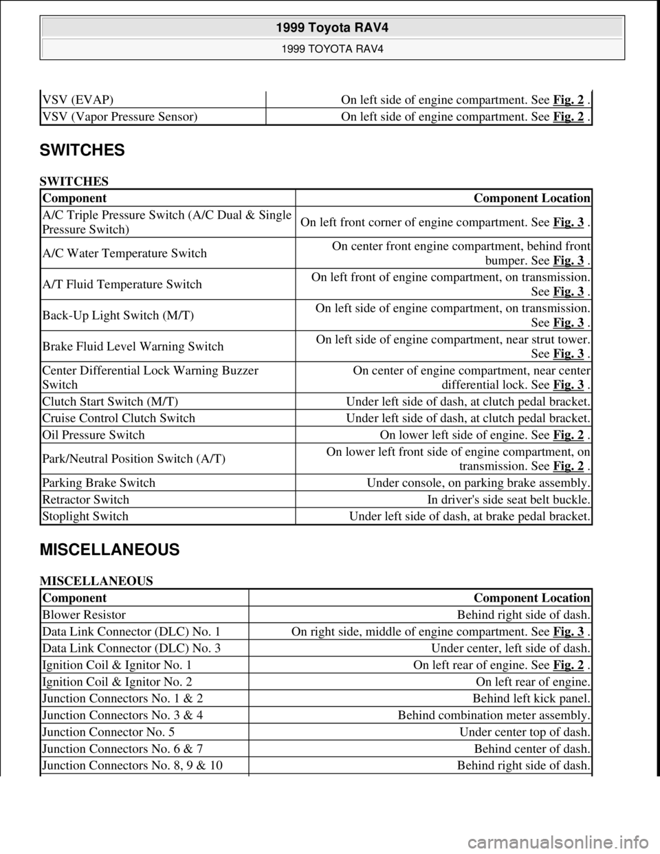
SWITCHES
SWITCHES
MISCELLANEOUS
MISCELLANEOUS
VSV (EVAP)On left side of engine compartment. See Fig. 2 .
VSV (Vapor Pressure Sensor)On left side of engine compartment. See Fig. 2 .
ComponentComponent Location
A/C Triple Pressure Switch (A/C Dual & Single
Pressure Switch)On left front corner of engine compartment. See Fig. 3 .
A/C Water Temperature SwitchOn center front engine compartment, behind front
bumper. See Fig. 3
.
A/T Fluid Temperature SwitchOn left front of engine compartment, on transmission.
See Fig. 3
.
Back-Up Light Switch (M/T)On left side of engine compartment, on transmission.
See Fig. 3
.
Brake Fluid Level Warning SwitchOn left side of engine compartment, near strut tower.
See Fig. 3
.
Center Differential Lock Warning Buzzer
SwitchOn center of engine compartment, near center
differential lock. See Fig. 3
.
Clutch Start Switch (M/T)Under left side of dash, at clutch pedal bracket.
Cruise Control Clutch SwitchUnder left side of dash, at clutch pedal bracket.
Oil Pressure SwitchOn lower left side of engine. See Fig. 2 .
Park/Neutral Position Switch (A/T)On lower left front side of engine compartment, on
transmission. See Fig. 2
.
Parking Brake SwitchUnder console, on parking brake assembly.
Retractor SwitchIn driver's side seat belt buckle.
Stoplight SwitchUnder left side of dash, at brake pedal bracket.
ComponentComponent Location
Blower ResistorBehind right side of dash.
Data Link Connector (DLC) No. 1On right side, middle of engine compartment. See Fig. 3 .
Data Link Connector (DLC) No. 3Under center, left side of dash.
Ignition Coil & Ignitor No. 1On left rear of engine. See Fig. 2 .
Ignition Coil & Ignitor No. 2On left rear of engine.
Junction Connectors No. 1 & 2Behind left kick panel.
Junction Connectors No. 3 & 4Behind combination meter assembly.
Junction Connector No. 5Under center top of dash.
Junction Connectors No. 6 & 7Behind center of dash.
Junction Connectors No. 8, 9 & 10Behind right side of dash.
1999 Toyota RAV4
1999 TOYOTA RAV4
Microsoft
Sunday, November 22, 2009 10:17:32 AMPage 4 © 2005 Mitchell Repair Information Company, LLC.
Page 693 of 1632
1. Remove driver-side rear seat and floor panel cover for access to fuel pump electrical connector.
2. Disconnect fuel pump electrical connector. Start engine and allow engine to idle until engine stalls. Turn
ignition off.
3. Reconnect fuel pump electrical connector. Reinstall floor panel cover and driver-side rear seat.
4. Disconnect negative battery cable. Place an approved gasoline container under fuel line. Cover fuel line
connection with shop towel.
5. Slowly loosen fuel line connection to release fuel pressure. Once fuel pressure is released, fuel system
components may be serviced.
ENGINE
Removal
1. Engine and transaxle are removed as an assembly from bottom of engine compartment. Release fuel
pressure. See FUEL PRESSURE RELEASE
. Remove hood, battery and battery tray. Drain cooling
system, and engine and transaxle oil.
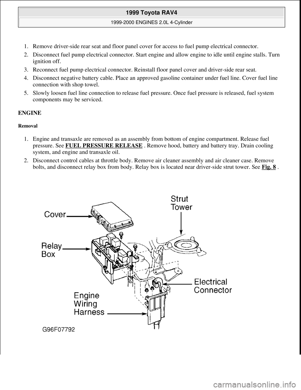
2. Disconnect control cables at throttle body. Remove air cleaner assembly and air cleaner case. Remove
bolts, and disconnect relay box from body. Relay box is located near driver-side strut tower. See Fig. 8
.
1999 Toyota RAV4
1999-2000 ENGINES 2.0L 4-Cylinder
Microsoft
Sunday, November 22, 2009 10:22:26 AMPage 10 © 2005 Mitchell Repair Information Company, LLC.