turn signal TOYOTA RAV4 1996 Service Repair Manual
[x] Cancel search | Manufacturer: TOYOTA, Model Year: 1996, Model line: RAV4, Model: TOYOTA RAV4 1996Pages: 1632, PDF Size: 41.64 MB
Page 7 of 1632
Turn ignition on. Measure voltage between terminals Tc and E1of DLC1. If voltage is 10-14 volts, circuit is
okay. If ABS warning light does not blink even after terminals are connected, malfunction may exist in ABS
ECU. If voltage is not 10-14 volts, check for open or short circuit in wiring harness between ABS actuator and
DLC1, or between ground and DLC1. See WIRING DIAGRAMS
. Repair as necessary. If wiring harness is
okay, replace ABS ECU.
TS TERMINAL
Circuit Description
Sensor check circuit detects abnormalities in speed sensor signal which cannot be detected when checking for
DTCs. Connecting terminals Ts and E
1 of DLC1 in engine compartment starts DTC check. See Fig. 2 .
Diagnostic Procedure
Turn ignition on. Measure voltage between terminals Ts and E1 of DLC1. If voltage is 10-14 volts, circuit is
okay. If ABS warning light does not blink even after terminals are connected, malfunction may exist in ABS
ECU. If voltage is not 10-14 volts, check for open or short circuit in wiring harness between ABS ECU and
DLC1, or between ground and DLC1. See WIRING DIAGRAMS
. Repair as necessary. If wiring harness is
okay, replace ABS ECU.
ABS ECU PIN VOLTAGES
ABS circuits and harness can be tested by backprobing ABS ECU connectors and comparing measured voltages
with ABS ECU standard values chart. See Fig. 3
.
1999 Toyota RAV4
1999-2000 BRAKES Anti-Lock - RAV4
Microsoft
Sunday, November 22, 2009 10:06:17 AMPage 7 © 2005 Mitchell Repair Information Company, LLC.
Page 14 of 1632
DTC 21, DTC 22, DTC 23 & DTC 24: ABS ACTUATOR SOLENOID CIRCUIT
Circuit Description
This solenoid turns on when signals are received from ABS ECU and controls pressure acting on calipers/wheel
cylinders, thus controlling braking force. If malfunction occurs in actuator solenoid circuit, ABS ECU cuts off
current to ABS control relay and prohibits ABS control.
DTC Detecting Conditions
If the following conditions continue for .05 seconds or more, DTC will set. Voltage at ABS control relay
connector terminal A9-1 is less than 1.5 volts, and one of the following conditions is met:
If power transistor of ABS ECU is on, and voltage at terminal SFRR or terminal SFRH is zero volts or
battery voltage is detected, DTC 21 will set.
If power transistor of ABS ECU is on, and voltage at terminal SFLR or terminal SFLH is zero volts or
battery voltage is detected, DTC 22 will set.
If power transistor of ABS ECU is on, and voltage at terminal SRRR or terminal SRRH is zero volts or
battery voltage is detected, DTC 23 will set.
If power transistor of ABS ECU is on, and voltage at terminal SRLR or terminal SRLH is zero volts or
battery voltage is detected, DTC 24 will set.
Diagnostic Procedure
1. Disconnect 2 ABS actuator connectors. Check continuity between actuator connector terminal A7- 4 and
actuator connector terminals A6-1 through A6-8. See Fig. 6
. Continuity should exist at each pair of
terminals. Check resistance at each pair of terminals. Resistance should be 4.3 ohms for each solenoid
coil at terminals SFRR, SFLR, SRRR and SRLR. Resistance should be 8.8 ohms for each solenoid coil at
terminals SFRH, SFLH, SRRH and SRLH. See WIRING DIAGRAMS
. If continuity and resistance is
as specified, go to next step. If continuity and resistance is not as specified, replace ABS actuator.
2. Check for open or short circuit in wiring harness between ABS ECU and actuator. Repair as necessary.
See WIRING DIAGRAMS
. If circuits are okay, go to next step.
3. Clear DTCs and then recheck for DTCs. See RETRIEVING DTCS
under DIAGNOSIS & TESTING. If
same DTC is output after DTC is cleared, check contact condition of each connection. Repair as
necessar
y. If connections are okay, replace ABS ECU.
1999 Toyota RAV4
1999-2000 BRAKES Anti-Lock - RAV4
Microsoft
Sunday, November 22, 2009 10:06:17 AMPage 14 © 2005 Mitchell Repair Information Company, LLC.
Page 18 of 1632
DTC 44: DECELERATION SENSOR CIRCUIT (4WD MODELS ONLY)
Circuit Description
Deceleration sensor detects vehicle deceleration. Sensor signal is used in ABS control. If sensor functions
abnormally, ABS warning light will illuminate, but ABS will still operate.
DTC Detecting Conditions
Detection of the following conditions may set DTC 44:
On 2-door models, with ignition switch in ON position, and output voltage of terminals GL1 or GL2
remains 0.5 volts or less or 4.5 volts or more for more than one minute, DTC 44 will set.
On 2-door models, at vehicle speed of zero MPH, if outputs of terminals GL1 and GL2 remain
abnormally different for one minute or more, DTC 44 will set.
On 2-door models, if after ignition switch is turned to ON position, voltage at terminal VGS is 4.4 volts
or less, or 5.5 volts or more, and voltage continues for 1.2 seconds or more, DTC 44 will set.
On 4-door models, if an open or short circuit is detected in circuits GS1 or GS2 for one second, DTC 44
will set.
On 4-door models, after ignition switch is turned to ON position, a test signal is output at terminal GST.
During this time, if a trouble signal is detected for 0.5 seconds, DTC 44 will set.
Diagnostic Procedure
1. Check for open or short circuit in wiring harness between deceleration sensor and ABS ECU. Repair as
necessary. See WIRING DIAGRAMS
. If wiring harness is okay, go to next step.
2. Turn ignition off. Remove ABS ECU. Do not disconnect electrical connectors. Disconnect deceleration
sensor connector. Turn ignition switch to ON position. On 4-door models, go to next step. On 2-door
models, measure voltage between ground and terminals GL1, GL2 and VGS at ABS ECU harness
connector. See Fig. 3
. Voltage should be 0.5-4.5 volts at terminals GL1 and GL2. Voltage should be 4.5-
5.5 volts at terminal VGS. If voltage is as specified, check deceleration sensor. See DECELERATION
SENSOR CHECK under COMPONENT TESTS. If voltage is not as specified, replace ABS ECU.
3. On 4-door models, measure voltage between ground and terminals GS1, GS2 and GST at ABS ECU
harness connector. See Fig. 3
. Voltage should be 4-6 volts or 7-11 volts at terminal GS1. Voltage should
be 4-6 volts at terminal GS2. Voltage at terminal GST should pulse from 12 volts for 0.5 seconds to zero
volts, with a 1.5 second pause between pulses. If voltage is as specified, check deceleration sensor. See
DECELERATION SENSOR CHECK
under COMPONENT TESTS. If voltage is not as specified,
replace ABS ECU.
DTC 49: STOPLIGHT SWITCH
DTC Detection Condition
Detection of the following condition may set DTC 49:
Voltage at ABS ECU terminal STP is 1.2-1.7 volts and continues for 0.3 seconds or more.
1999 Toyota RAV4
1999-2000 BRAKES Anti-Lock - RAV4
Microsoft
Sunday, November 22, 2009 10:06:17 AMPage 18 © 2005 Mitchell Repair Information Company, LLC.
Page 65 of 1632
Fig. 1: Locating Restraint System Components
Courtesy of TOYOTA MOTOR SALES, U.S.A., INC.
AIR BAG SENSOR ASSEMBLY
The air bag sensor assembly is located on the floor inside center console box. It consists of an air bag sensor,
safing sensor and diagnosis, ignition control and drive circuits. It receives signals from the air bag sensor and
determines whether air bag system must be deployed or not.
DRIVER-SIDE AIR BAG MODULE
The driver-side air bag and inflator is stored in the steering wheel pad. It contains a squib, igniter charge and gas
generant and inflates the air bag when instructed by air bag sensor assembly. Driver-side air bag module is also
called steering wheel pad.
FRONT AIR BAG SENSOR
The front air bag sensors are mounted inside right and left front side members. When sensor detects an impact
of sufficient force (above a predetermined limit), contacts inside the sensor close, sending a signal to the air bag
sensor assembly.
PASSENGER-SIDE AIR BAG MODULE
The passenger-side air bag and inflator is stored in the instrument panel above glove box. It contains a squib,
igniter charge and gas generant and inflates the air bag when instructed by air bag sensor assembly.
SEAT BELT PRETENSIONER
The seat belt pretensioner system is a component of the front outer seat belt assembly. It contains a squib, gas
generant, wire and piston and operates in the event of a front-end collision.
SPIRAL CABLE
The spiral cable is attached to combination switch and is used as an electrical joint between chassis wiring
harness and driver-side air bag module. Spiral cable is also known as clockspring.
SERVICE PRECAUTIONS
Observe the following precautions when servicing air bag system:
Disable air bag system before servicing any air bag system or steering column component. Failure to do
this could result in accidental air bag deployment and possible personal injury. See DISABLING &
ACTIVATING AIR BAG SYSTEM .
When diagnosing air bag system, always check for diagnostic codes before disconnecting battery.
After turning ignition switch to LOCK position and disconnecting negative battery cable, wait at least 90
seconds before workin
g on air bag system. Air bag system is equipped with a back-up power source that
1999 Toyota RAV4
AIR BAG RESTRAINT SYSTEM 1999 Toyota
Microsoft
Sunday, November 22, 2009 10:33:22 AMPage 2 © 2005 Mitchell Repair Information Company, LLC.
Page 98 of 1632
8. Connect jumper wire between White/Red and Brown wires of front air bag sensor side of sub-harness
connector located at left kick panel. Measure resistance between White/Red and Brown wires of air bag
sensor assembly side of front air bag sensor harness connector. If resistance is more than one ohm,
replace sub-wire harness between sensor and kick panel. If resistance is less than one ohm, repair or
replace harness or connector between air bag sensor assembly and sub-wire harness.
9. Disconnect right front air bag sensor connector. Measure resistance between ground and air bag sensor
assembly connector C20, terminal No. 15 (circuit SL+, White/Red wire). Measure resistance between
ground and air bag sensor assembly connector C20, terminal No. 26 (circuit SL-, Brown wire). If
resistance is less than one megohm, go to next step. If resistance is more than one megohm, replace left
front air bag sensor.
10. Disconnect left front air bag sensor Yellow 2-pin sub-harness connector. Connector is located at left kick
panel. See Fig. 4
. Measure resistance between ground and White/Red and Brown wires of front air bag
sensor side of sub-harness kick panel connector individually. If resistance is more than one megohm,
repair or replace harness or connector between air bag sensor assembly and sub-harness. If resistance is
less than one megohm, replace sub-harness between sensor and kick panel.
11. Disconnect left front air bag sensor connector. Measure voltage between ground and air bag sensor
assembly connector C20, terminal No. 15 (circuit SL+, White/Red wire). Measure voltage between
ground and air bag sensor assembly connector C20, terminal No. 26 (circuit SL-, Brown wire). If voltage
is more than one volt, go to next step. If voltage is less than one volt, replace left front air bag sensor.
12. Disconnect left front air bag sensor Yellow 2-pin sub-harness connector. Connector is located at left kick
panel. See Fig. 4
. Measure voltage between ground and White/Red and Brown wires of front air bag
sensor side of sub-harness kick panel connector individually. If voltage is more than one volt, repair or
replace sub-harness between sensor and kick panel. If voltage is less than one volt, repair or replace
harness or connector between air bag sensor assembly and sub-harness.
DTC 31/B1100: AIR BAG SENSOR ASSEMBLY MALFUNCTION
Description
The air bag sensor assembly consists of an air bag sensor, safing sensor, drive circuit, diagnosis circuit and
ignition control circuit. The air bag sensor assembly receives signals from air bag sensor, judges whether or not
the air bag must be deployed and detects diagnosis system malfunction.
Possible Causes
DTC 31/B1100 could be caused by a air bag sensor assembly malfunction.
Diagnostic Procedure
1. Disable air bag system. See DISABLING SYSTEM under DISABLING & ACTIVATING AIR BAG
SYSTEM. Reconnect negative battery cable.
2. Turn i
gnition switch to ON position. Measure voltage between ground and air bag sensor assembly NOTE: If a DTC other than DTC 31/B1100 is displayed at same time as DTC 31/B1100,
repair fault indicated by DTC other than DTC 31/B1100 before using this
procedure.
1999 Toyota RAV4
AIR BAG RESTRAINT SYSTEM 1999 Toyota
Microsoft
Sunday, November 22, 2009 10:33:23 AMPage 35 © 2005 Mitchell Repair Information Company, LLC.
Page 279 of 1632
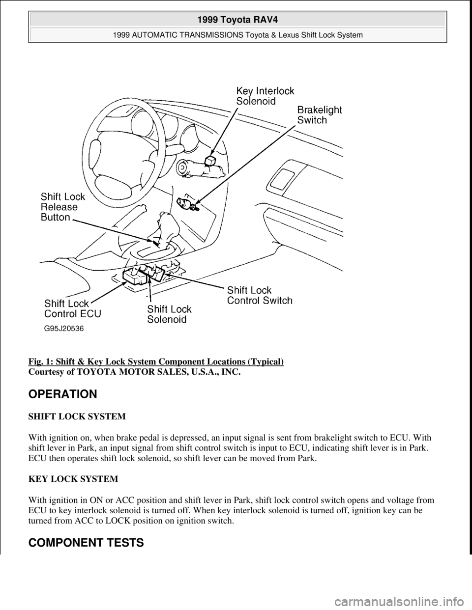
Fig. 1: Shift & Key Lock System Component Locations (Typical)
Courtesy of TOYOTA MOTOR SALES, U.S.A., INC.
OPERATION
SHIFT LOCK SYSTEM
With ignition on, when brake pedal is depressed, an input signal is sent from brakelight switch to ECU. With
shift lever in Park, an input signal from shift control switch is input to ECU, indicating shift lever is in Park.
ECU then operates shift lock solenoid, so shift lever can be moved from Park.
KEY LOCK SYSTEM
With ignition in ON or ACC position and shift lever in Park, shift lock control switch opens and voltage from
ECU to key interlock solenoid is turned off. When key interlock solenoid is turned off, ignition key can be
turned from ACC to LOCK position on ignition switch.
COMPONENT TESTS
1999 Toyota RAV4
1999 AUTOMATIC TRANSMISSIONS Toyota & Lexus Shift Lock System
Microsoft
Sunday, November 22, 2009 10:46:00 AMPage 2 © 2005 Mitchell Repair Information Company, LLC.
Page 527 of 1632
OPERATION
Cruise control system functions can be performed from cruise control switch, located on lever on right side of
steering column. Pressing cruise ON-OFF (main) switch at end of lever turns system on. CRUISE indicator
light in instrument cluster comes on when desired cruising speed is set. To set desired speed, move control lever
downward in SET/COAST direction and release it. Desired speed should be maintained. Press cruise ON-OFF
(main) switch again to turn cruise control system off.
Cancel set speed by moving cruise control lever in CANCEL direction, pressing brake pedal, or pressing clutch
pedal (M/T) or placing shift lever in Neutral (A/T). If vehicle speed drops to less than 25 MPH, set speed will
automatically cancel. If vehicle speed decreases 10 MPH less than set speed, set speed will also cancel. If cruise
control ECU detects a system malfunction, set speed will automatically cancel and CRUISE indicator light will
flash several times.
Moving cruise control lever in RES/ACC (resume/accelerate) direction allows vehicle to return to speed set
before cancellation. Holding cruise control lever in RES/ACC (resume/accelerate) direction gradually increases
vehicle speed. Holding cruise control lever in SET/COAST direction gradually decreases vehicle speed.
ACTUATOR
Actuator consists of a motor, safety magnetic clutch, position sensor, pulley and a cable connected to engine
throttle valve. When actuator receives a signal from cruise control ECU, it engages safety magnetic clutch and
activates motor. Motor causes pulley and cable to move, which will open or close engine throttle valve.
When motor rotates forward, pulley also rotates (via safety magnetic clutch, gears and drive shaft). A cable
connected to engine throttle valve and opens valve accordingly. When motor rotates in a reverse direction,
pulley and cable also rotate in a reverse direction and engine throttle valve closes.
CRUISE CONTROL SWITCH
ON-OFF (Main Switch)
Cruise ON-OFF switch is power switch for cruise control system. When ignition is turned off, cruise ON-OFF
switch is also turned off. The switch remains off even when ignition is turned on again.
SET/COAST Position
When cruise control switch is moved to SET/COAST position with cruise ON-OFF switch turned to ON
position and vehicle speed greater than 25 MPH, cruise control ECU stores vehicle speed and maintains that
speed via actuator.
When cruise control switch is moved to SET/COAST position while in cruise control mode, actuator motor is
energized to close engine throttle valve. Vehicle decelerates until switch is released. From then on, cruise
control ECU stores new vehicle speed and maintains that speed.
RES/ACC Position
1999 Toyota RAV4
1999 ACCESSORIES & EQUIPMENT Cruise Control Systems - RAV4
Microsoft
Sunday, November 22, 2009 10:52:01 AMPage 3 © 2005 Mitchell Repair Information Company, LLC.
Page 534 of 1632
FUNCTION TEST under TROUBLE SHOOTING. If SET/COAST, RES/ACC or CANCEL input
signals are not as specified, go to next step. If input signals are as specified, no problem is indicated at
this time. Fault may be intermittent. If sent here from SYMPTOM DIAGNOSIS, perform next test listed,
go to next step. If input signals are as specified, no problem is indicated at this time. Fault may be
intermittent. If sent here from SYMPTOM DIAGNOSIS, perform next test listed.
2. Remove cruise control ECU with connector attached. See Fig. 1
. Turn ignition switch to ON position.
Backprobing connector, measure voltage between cruise control ECU connector terminal No. 10
(Green/Yellow wire) and ground with switch in specified positions. See CRUISE CONTROL ECU
VOLTAGE SPECIFICATIONS table. If voltage is not as specified, go to next step. If voltage is as
specified, no problem is indicated at this time. Fault may be intermittent. If sent here from SYMPTOM
DIAGNOSIS, perform next test listed.
CRUISE CONTROL ECU VOLTAGE SPECIFICATIONS
3. Turn ignition switch to OFF position. Disable air bag system. See AIR BAG RESTRAINT SYSTEMS
article. Remove steering wheel center pad (air bag module) and disconnect CRUISE control switch 6-pin
connector. Measure resistance between cruise control switch connector terminals No. 4 (White/Black
wire) and No. 5 (Green/Yellow wire) with switch in specified positions. See CRUISE CONTROL
SWITCH RESISTANCES table. If resistance is as specified, go to next step. If resistance is not as
specified, replace cruise control switch and retest system.
CRUISE CONTROL SWITCH RESISTANCES
4. Check for continuity between cruise control switch terminals No. 4 (White/Black wire) and No. 5
(Green/Yellow wire). No continuity should exist with cruise control switch in OFF position. Continuity
should exist with cruise control switch held in ON position. If continuity is as specified, go to next step. I
f
continuity is not as specified, replace cruise control switch and retest system.
5. Check wiring harness and connectors between cruise control ECU, cruise control switch and ground.
Repair as necessary and retest system. If wiring harness and connectors are okay, go to next step.
6. Repeat step 1 . If SET/COAST, RES/ACC or CANCEL input signals are still not as specified, replace
cruise control ECU and retest system. If input signals are as specified, no problem is indicated at this
time. Fault may be intermittent. If sent here from SYMPTOM DIAGNOSIS, perform next test listed.
STOPLIGHT SWITCH CIRCUIT
Switch PositionVolts
Off10-16
RES/ACC On0.6-2.3
SET/COAST On1.9-4.7
CANCEL On3.4-7.2
Switch PositionOhms
OffOne Megohm Or Greater
RES/ACC On50-80
SET/COAST On180-220
CANCEL On400-440
1999 Toyota RAV4
1999 ACCESSORIES & EQUIPMENT Cruise Control Systems - RAV4
Microsoft
Sunday, November 22, 2009 10:52:01 AMPage 10 © 2005 Mitchell Repair Information Company, LLC.
Page 535 of 1632
1. Check stoplight operation. If stoplight operation is okay, go to next step. If stoplights DO NOT operate
correctly, check and repair stoplight system as necessary. See WIRING DIAGRAMS
.
2. Perform CANCEL SWITCHES test under CRUISE CONTROL FUNCTION TEST
under TROUBLE
SHOOTING. If stoplight input signal is not as specified, go to next step. If stoplight input signal is as
specified, no problem is indicated at this time. Fault may be intermittent. If sent here from SYMPTOM
DIAGNOSIS, perform next test listed.
3. Remove cruise control ECU with connector attached. See Fig. 1
. Turn ignition switch to ON position.
Backprobing cruise control ECU connector, measure voltage between ground and cruise control ECU
connector terminal No. 2 (Green/White wire). With brake pedal depressed, battery voltage should exist.
With brake pedal released, voltage should be less than one volt. If voltage is not as specified, go to next
step. If voltage is as specified, no problem is indicated at this time. Fault may be intermittent. If sent here
from SYMPTOM DIAGNOSIS, perform next test listed.
4. Check for open circuit in wiring harness and connectors between cruise control ECU and stoplight switch.
Repair as necessary and retest system. If wiring harness and connectors are okay, replace cruise control
ECU and retest system.
IDLE SIGNAL CIRCUIT
1. Remove cruise control ECU with connector attached. Disconnect Engine Control Module (ECM) 16-pin
connector. ECM is located behind bottom center of instrument panel, in front of console. Turn ignition
switch to ON position. Backprobing connector, measure voltage between ground and cruise control ECU
connector terminal No. 13 (Blue wire).
2. With throttle valve fully open, battery voltage should exist. With throttle valve fully closed, voltage
should be less than 2 volts. If voltage is not as specified, go to next step. If voltage is as specified, no
problem is indicated at this time. Fault may be intermittent. If sent here from SYMPTOM DIAGNOSIS,
perform next test listed.
3. Check wiring harness and connectors between ECM and TP sensor. Repair as necessary and retest
system. If wiring harness and connectors are okay, go to next step.
4. Disconnect TP sensor 3-pin Black connector. Measure resistance between TP sensor connector terminals
No. 2 (Brown wire) and No. 3 (Blue/Red wire). Resistance should be 2000-10,200 ohms with throttle
valve fully opened, and 200-6300 ohms with throttle valve fully closed. If resistance is as specified, go to
next step. If resistance is not as specified, replace TP sensor and retest system.
5. Check wiring harness and connectors between cruise control ECU and TP sensor, and between TP sensor
and ground. Repair as necessary and retest system. If wiring harness and connectors are okay, replace
cruise control ECU and retest system.
ELECTRONICALLY CONTROLLED TRANSMISSION (ECT) CIRCUIT
1. Start engine and bring to operating temperature. Drive vehicle and ensure overdrive operation is turned on
and off when overdrive ON-OFF switch is operated. If overdrive switch is okay, go to next step. If
overdrive switch is not okay, see appropriate ELECTRONIC CONTROLS article in AUTOMATIC NOTE: Ensure Throttle Position (TP) sensor circuit is operating as designed, and no
fault codes are present for TP sensor circuit. See appropriate ON-VEHICLE
ADJUSTMENTS article in ENGINE PERFORMANCE.
1999 Toyota RAV4
1999 ACCESSORIES & EQUIPMENT Cruise Control Systems - RAV4
Microsoft
Sunday, November 22, 2009 10:52:01 AMPage 11 © 2005 Mitchell Repair Information Company, LLC.
Page 536 of 1632
TRANSMISSIONS article.
2. Turn ignition switch to OFF position. Remove cruise control ECU and disconnect connector. See Fig. 1
.
Turn ignition switch to ON position. Using voltmeter positive lead, backprobe cruise control ECU
harness connector terminal No. 14 (Yellow/Black wire) with negative lead to ground. If battery voltage is
present, go to next step. If battery voltage is not present, go to step 5 .
3. Turn ignition switch to OFF position. Reconnect cruise control ECU connector. Using voltmeter positive
lead, backprobe cruise control ECU connector terminal No. 6 (Pink wire) with negative lead to ground.
Bring engine to operating temperature and test drive vehicle with overdrive switch moved from ON to
OFF position. With overdrive in OFF position, voltage should be less than .5 volt. With overdrive in ON
position, battery voltage should be present. If voltage is not as specified, go to next step. If voltage is as
specified, no problem is indicated at this time. Fault may be intermittent. If sent here from SYMPTOM
DIAGNOSIS, perform next test listed.
4. Check wiring harness and connectors between cruise control ECU terminal No. 6 (Pink wire) and
electronically controlled transmission solenoid. Repair as necessary. If wiring harness and connectors are
okay, replace cruise control ECU and retest system.
5. Check wiring harness and connectors between cruise control ECU connector terminal No. 14
(Yellow/Black wire) and Engine Control Module (ECM) 22-pin connector terminal No. 20
(Yellow/Black wire). Repair as necessary. If wiring harness and connectors are okay, replace cruise
control ECU and retest system.
PARK/NEUTRAL POSITION SWITCH CIRCUIT
1. Ensure starting system is operating normally. Check for starting system problems and repair as necessary.
See STARTERS article in STARTING & CHARGING SYSTEMS. If starting system is okay, go to next
step.
2. Perform park/neutral position switch test. See CANCEL SWITCHES test in CRUISE CONTROL
FUNCTION TEST under TROUBLE SHOOTING. If park/neutral position switch input signal is not as
specified, go to next step. If park/neutral position switch input signal is as specified, no problem is
indicated at this time. Fault may be intermittent. If sent here from SYMPTOM DIAGNOSIS, perform
next test listed.
3. Remove cruise control ECU with connector attached. See Fig. 1
. Turn ignition switch to ON position.
Backprobing connector, measure voltage between ground and terminal No. 3 (Blue/Black wire) at cruise
control ECU connector. With shift lever in Drive, battery voltage should be present. With shift lever in
any other position, voltage should be less than one volt. If voltage is not as specified, go to next step. If
voltage is as specified, no problem is indicated at this time. Fault may be intermittent. If sent here from
SYMPTOM DIAGNOSIS, perform next test listed.
4. Check wiring harness and connectors between cruise control ECU and park/neutral position switch.
Repair as necessary. If wiring harness and connectors are okay, replace cruise control ECU and retest
system.
CLUTCH SWITCH CIRCUIT
1. Ensure starting system is operating normally. Check for starting system problems and repair as necessary.
If starting system is okay, go to next step.
2. Perform clutch switch position test. See CANCEL SWITCHES test in CRUISE CONTROL
1999 Toyota RAV4
1999 ACCESSORIES & EQUIPMENT Cruise Control Systems - RAV4
Microsoft
Sunday, November 22, 2009 10:52:01 AMPage 12 © 2005 Mitchell Repair Information Company, LLC.