sensor TOYOTA RAV4 2006 Service Repair Manual
[x] Cancel search | Manufacturer: TOYOTA, Model Year: 2006, Model line: RAV4, Model: TOYOTA RAV4 2006Pages: 2000, PDF Size: 45.84 MB
Page 831 of 2000
EC–222AZ-FE EMISSION CONTROL – AIR FUEL RATIO SENSOR
EC
REMOVAL
1. DISCONNECT CABLE FROM NEGATIVE BATTERY
TERMINAL
CAUTION:
Wait at least 90 seconds after disconnecting the
cable from the negative (-) battery terminal to
prevent airbag and seat belt pretensioner activation.
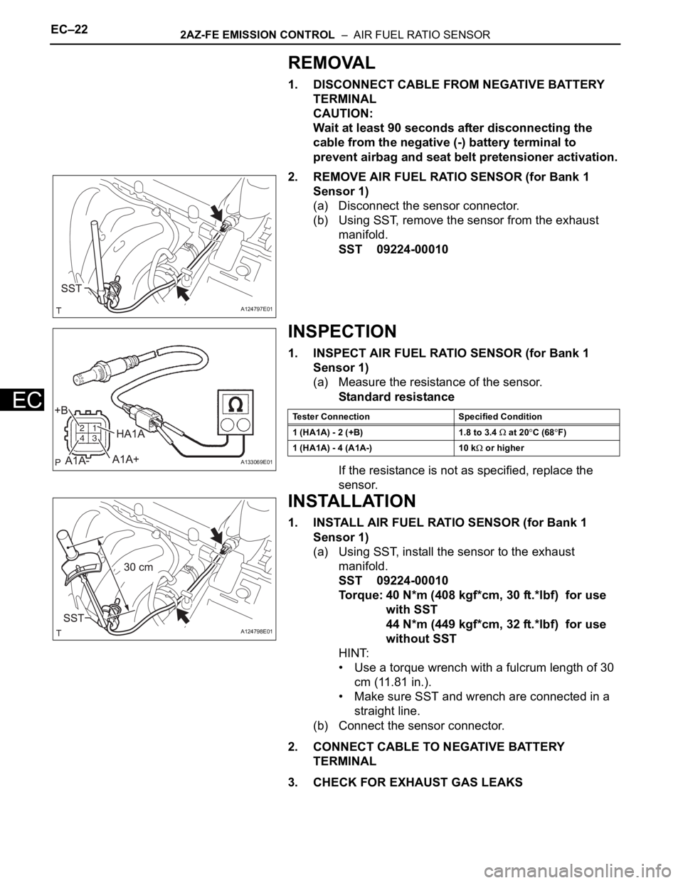
2. REMOVE AIR FUEL RATIO SENSOR (for Bank 1
Sensor 1)
(a) Disconnect the sensor connector.
(b) Using SST, remove the sensor from the exhaust
manifold.
SST 09224-00010
INSPECTION
1. INSPECT AIR FUEL RATIO SENSOR (for Bank 1
Sensor 1)
(a) Measure the resistance of the sensor.
Standard resistance
If the resistance is not as specified, replace the
sensor.
INSTALLATION
1. INSTALL AIR FUEL RATIO SENSOR (for Bank 1
Sensor 1)
(a) Using SST, install the sensor to the exhaust
manifold.
SST 09224-00010
Torque: 40 N*m (408 kgf*cm, 30 ft.*lbf) for use
with SST
44 N*m (449 kgf*cm, 32 ft.*lbf) for use
without SST
HINT:
• Use a torque wrench with a fulcrum length of 30
cm (11.81 in.).
• Make sure SST and wrench are connected in a
straight line.
(b) Connect the sensor connector.
2. CONNECT CABLE TO NEGATIVE BATTERY
TERMINAL
3. CHECK FOR EXHAUST GAS LEAKS
A124797E01
A133069E01
Tester Connection Specified Condition
1 (HA1A) - 2 (+B) 1.8 to 3.4
at 20C (68F)
1 (HA1A) - 4 (A1A-) 10 k
or higher
A124798E01
Page 838 of 2000
EC–242GR-FE EMISSION CONTROL – AIR FUEL RATIO SENSOR
EC
INSTALLATION
1. INSTALL AIR FUEL RATIO SENSOR (for Sensor 1)
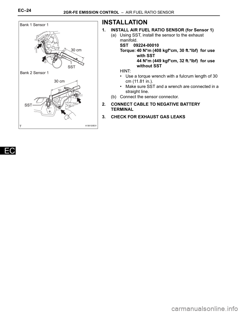
(a) Using SST, install the sensor to the exhaust
manifold.
SST 09224-00010
Torque: 40 N*m (408 kgf*cm, 30 ft.*lbf) for use
with SST
44 N*m (449 kgf*cm, 32 ft.*lbf) for use
without SST
HINT:
• Use a torque wrench with a fulcrum length of 30
cm (11.81 in.).
• Make sure SST and a wrench are connected in a
straight line.
(b) Connect the sensor connector.
2. CONNECT CABLE TO NEGATIVE BATTERY
TERMINAL
3. CHECK FOR EXHAUST GAS LEAKS
A136120E01
Page 839 of 2000
EC–262GR-FE EMISSION CONTROL – HEATED OXYGEN SENSOR
EC
REMOVAL
1. DISCONNECT CABLE FROM NEGATIVE BATTERY
TERMINAL
CAUTION:
Wait at least 90 seconds after disconnecting the
cable from the negative (-) battery terminal to
prevent airbag and seat belt pretensioner activation.
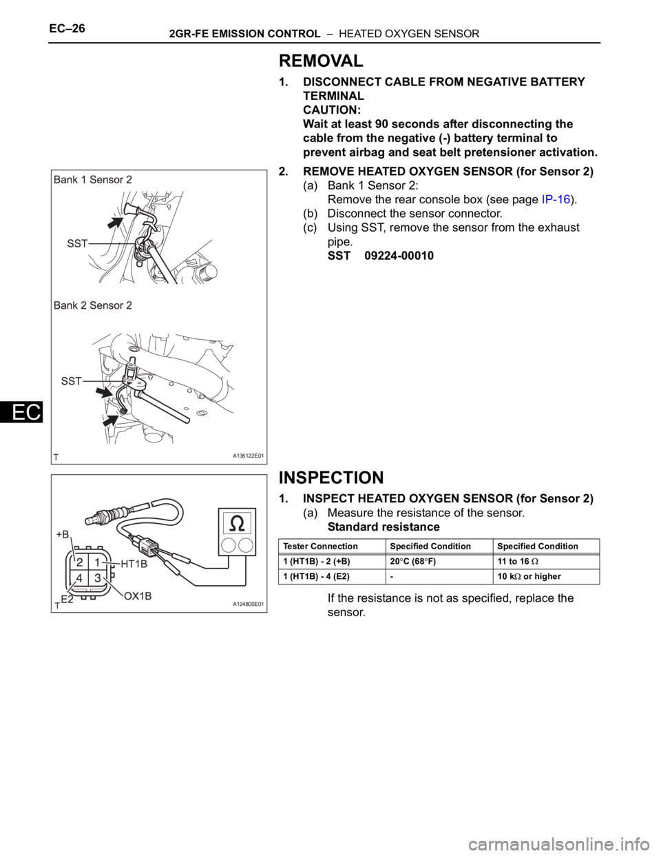
2. REMOVE HEATED OXYGEN SENSOR (for Sensor 2)
(a) Bank 1 Sensor 2:
Remove the rear console box (see page IP-16).
(b) Disconnect the sensor connector.
(c) Using SST, remove the sensor from the exhaust
pipe.
SST 09224-00010
INSPECTION
1. INSPECT HEATED OXYGEN SENSOR (for Sensor 2)
(a) Measure the resistance of the sensor.
Standard resistance
If the resistance is not as specified, replace the
sensor.
A136122E01
A124800E01
Tester Connection Specified Condition Specified Condition
1 (HT1B) - 2 (+B) 20
C (68F) 11 to 16
1 (HT1B) - 4 (E2) - 10 k or higher
Page 840 of 2000
2GR-FE EMISSION CONTROL – HEATED OXYGEN SENSOREC–27
EC
INSTALLATION
1. INSTALL HEATED OXYGEN SENSOR (for Sensor 2)
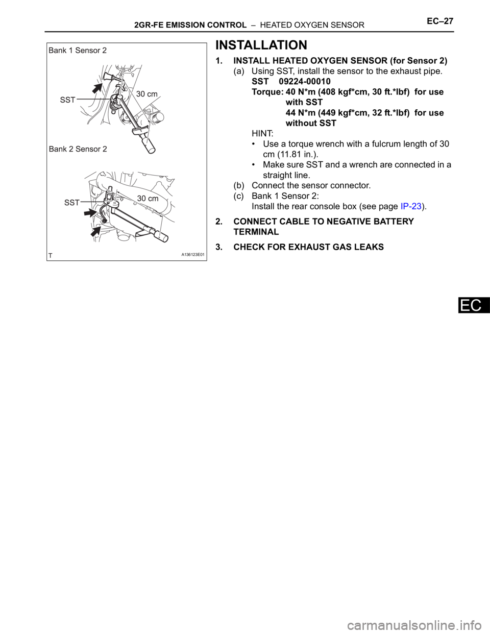
(a) Using SST, install the sensor to the exhaust pipe.
SST 09224-00010
Torque: 40 N*m (408 kgf*cm, 30 ft.*lbf) for use
with SST
44 N*m (449 kgf*cm, 32 ft.*lbf) for use
without SST
HINT:
• Use a torque wrench with a fulcrum length of 30
cm (11.81 in.).
• Make sure SST and a wrench are connected in a
straight line.
(b) Connect the sensor connector.
(c) Bank 1 Sensor 2:
Install the rear console box (see page IP-23).
2. CONNECT CABLE TO NEGATIVE BATTERY
TERMINAL
3. CHECK FOR EXHAUST GAS LEAKS
A136123E01
Page 841 of 2000
2AZ-FE COOLING – WATER PUMPCO–11
CO
REMOVAL
1. DISCONNECT CABLE FROM NEGATIVE BATTERY
TERMINAL
CAUTION:
Wait at least 90 seconds after disconnecting the
cable from the negative (-) battery terminal to
prevent airbag and seat belt pretensioner activation.
2. REMOVE NO. 1 ENGINE UNDER COVER
3. REMOVE FRONT FENDER APRON RH
4. REMOVE RADIATOR SUPPORT OPENING COVER
5. DRAIN ENGINE COOLANT (See page CO-6)
6. REMOVE FRONT SUSPENSION MEMBER
REINFORCEMENT RH (See page EM-6)
7. REMOVE FAN AND GENERATOR V BELT (See page
EM-6)
8. REMOVE GENERATOR ASSEMBLY (See page CH-9)
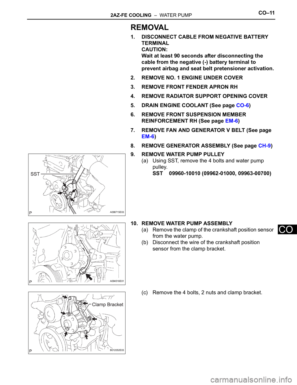
9. REMOVE WATER PUMP PULLEY
(a) Using SST, remove the 4 bolts and water pump
pulley.
SST 09960-10010 (09962-01000, 09963-00700)
10. REMOVE WATER PUMP ASSEMBLY
(a) Remove the clamp of the crankshaft position sensor
from the water pump.
(b) Disconnect the wire of the crankshaft position
sensor from the clamp bracket.
(c) Remove the 4 bolts, 2 nuts and clamp bracket.
A098715E03
A094516E01
B012052E03
Page 843 of 2000
2AZ-FE COOLING – WATER PUMPCO–13
CO
INSTALLATION
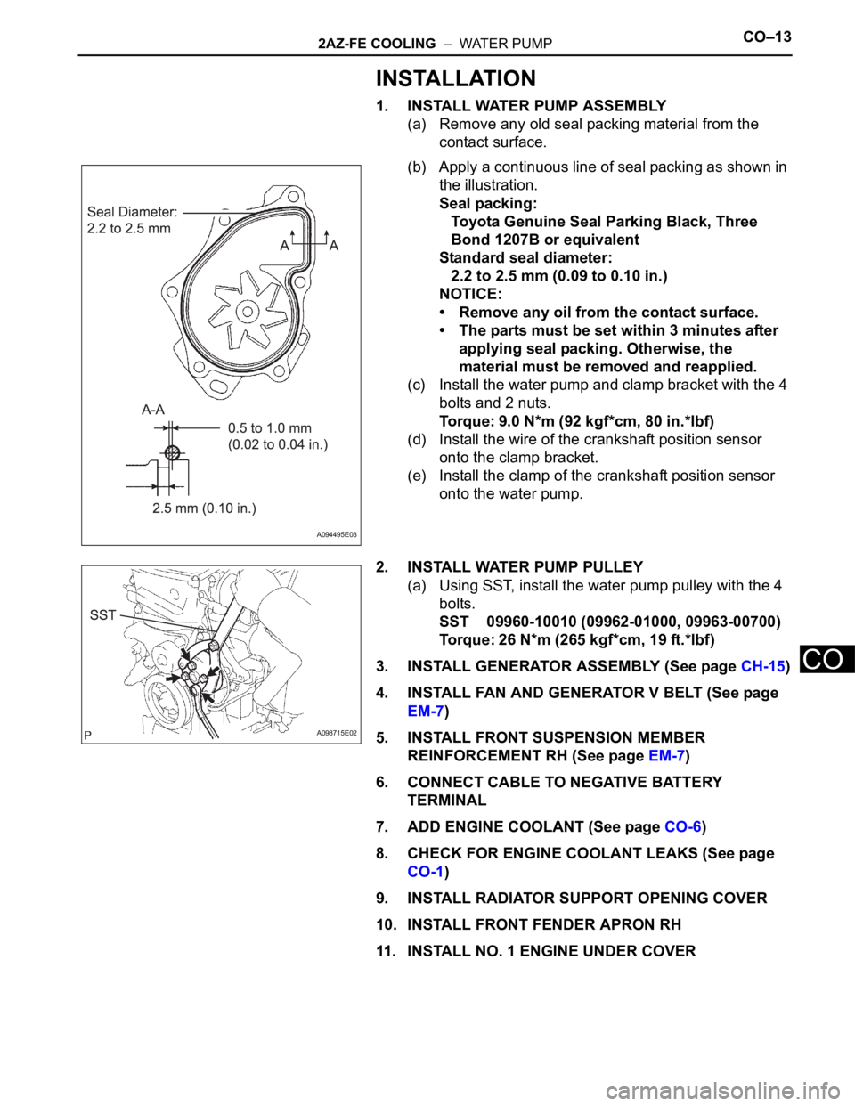
1. INSTALL WATER PUMP ASSEMBLY
(a) Remove any old seal packing material from the
contact surface.
(b) Apply a continuous line of seal packing as shown in
the illustration.
Seal packing:
Toyota Genuine Seal Parking Black, Three
Bond 1207B or equivalent
Standard seal diameter:
2.2 to 2.5 mm (0.09 to 0.10 in.)
NOTICE:
• Remove any oil from the contact surface.
• The parts must be set within 3 minutes after
applying seal packing. Otherwise, the
material must be removed and reapplied.
(c) Install the water pump and clamp bracket with the 4
bolts and 2 nuts.
Torque: 9.0 N*m (92 kgf*cm, 80 in.*lbf)
(d) Install the wire of the crankshaft position sensor
onto the clamp bracket.
(e) Install the clamp of the crankshaft position sensor
onto the water pump.
2. INSTALL WATER PUMP PULLEY
(a) Using SST, install the water pump pulley with the 4
bolts.
SST 09960-10010 (09962-01000, 09963-00700)
Torque: 26 N*m (265 kgf*cm, 19 ft.*lbf)
3. INSTALL GENERATOR ASSEMBLY (See page CH-15)
4. INSTALL FAN AND GENERATOR V BELT (See page
EM-7)
5. INSTALL FRONT SUSPENSION MEMBER
REINFORCEMENT RH (See page EM-7)
6. CONNECT CABLE TO NEGATIVE BATTERY
TERMINAL
7. ADD ENGINE COOLANT (See page CO-6)
8. CHECK FOR ENGINE COOLANT LEAKS (See page
CO-1)
9. INSTALL RADIATOR SUPPORT OPENING COVER
10. INSTALL FRONT FENDER APRON RH
11. INSTALL NO. 1 ENGINE UNDER COVER
A094495E03
A098715E02
Page 854 of 2000
CO–62GR-FE COOLING – COOLING FAN SYSTEM
CO
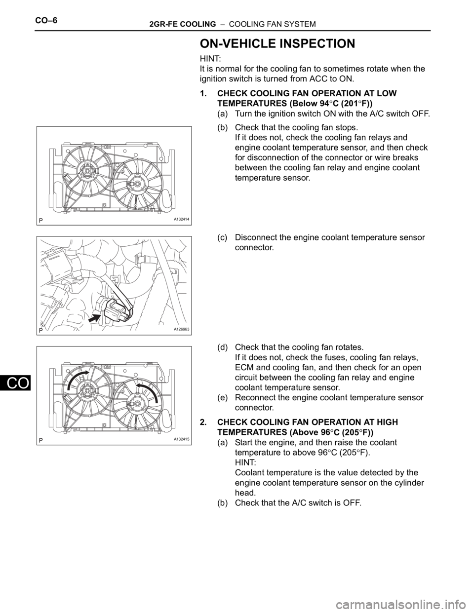
ON-VEHICLE INSPECTION
HINT:
It is normal for the cooling fan to sometimes rotate when the
ignition switch is turned from ACC to ON.
1. CHECK COOLING FAN OPERATION AT LOW
TEMPERATURES (Below 94
C (201F))
(a) Turn the ignition switch ON with the A/C switch OFF.
(b) Check that the cooling fan stops.
If it does not, check the cooling fan relays and
engine coolant temperature sensor, and then check
for disconnection of the connector or wire breaks
between the cooling fan relay and engine coolant
temperature sensor.
(c) Disconnect the engine coolant temperature sensor
connector.
(d) Check that the cooling fan rotates.
If it does not, check the fuses, cooling fan relays,
ECM and cooling fan, and then check for an open
circuit between the cooling fan relay and engine
coolant temperature sensor.
(e) Reconnect the engine coolant temperature sensor
connector.
2. CHECK COOLING FAN OPERATION AT HIGH
TEMPERATURES (Above 96
C (205F))
(a) Start the engine, and then raise the coolant
temperature to above 96
C (205F).
HINT:
Coolant temperature is the value detected by the
engine coolant temperature sensor on the cylinder
head.
(b) Check that the A/C switch is OFF.
A132414
A126963
A132415
Page 855 of 2000
2GR-FE COOLING – COOLING FAN SYSTEMCO–7
CO
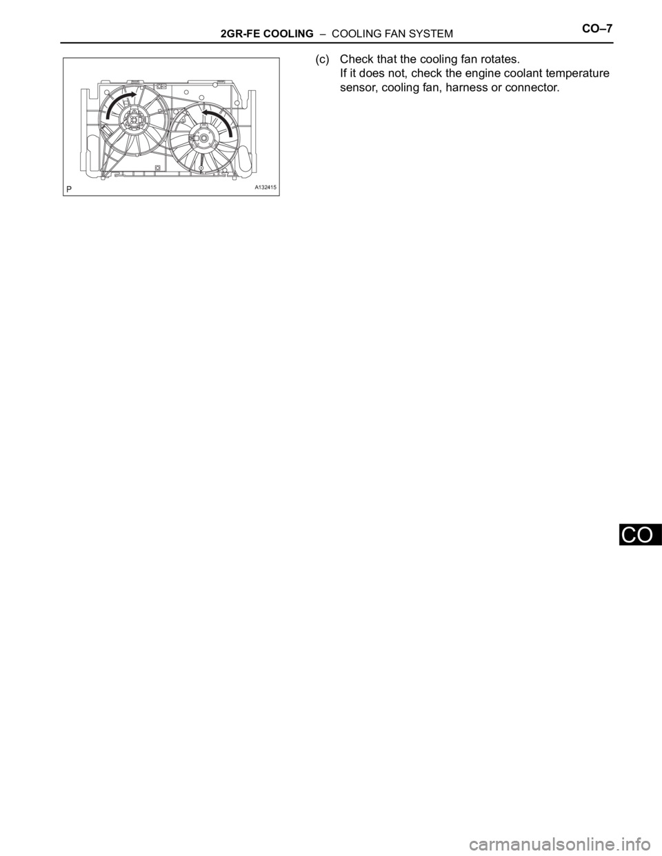
(c) Check that the cooling fan rotates.
If it does not, check the engine coolant temperature
sensor, cooling fan, harness or connector.
A132415
Page 886 of 2000
IG–62AZ-FE IGNITION – IGNITION SYSTEM
IG
(9) Install the ignition coil with the bolt.
Torque: 9.0 N*m (92 kgf*cm, 80 in.*lbf)
(10) Connect the 4 fuel injector connectors.
(11) Install the No. 1 engine cover.
(c) Spark test flow chart.
(1) Check that the ignition coil connector is
securely connected.
Result
(2) Perform the spark test on each ignition coil.
1. Replace the ignition coil with a normal one.
2. Perform the spark test again.
Result
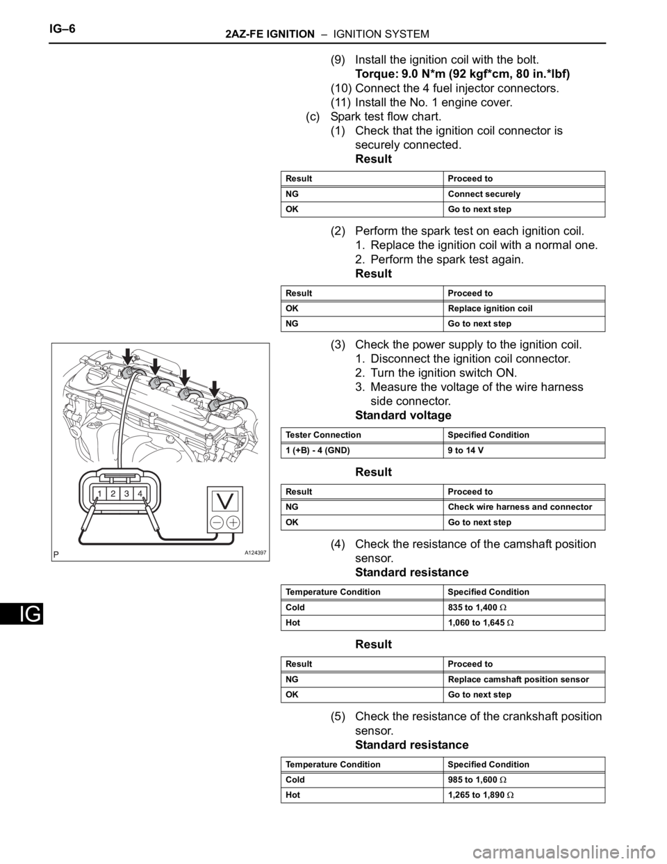
(3) Check the power supply to the ignition coil.
1. Disconnect the ignition coil connector.
2. Turn the ignition switch ON.
3. Measure the voltage of the wire harness
side connector.
Standard voltage
Result
(4) Check the resistance of the camshaft position
sensor.
Standard resistance
Result
(5) Check the resistance of the crankshaft position
sensor.
Standard resistance
Result Proceed to
NG Connect securely
OK Go to next step
Result Proceed to
OK Replace ignition coil
NG Go to next step
A124397
Tester Connection Specified Condition
1 (+B) - 4 (GND) 9 to 14 V
Result Proceed to
NG Check wire harness and connector
OK Go to next step
Temperature Condition Specified Condition
Cold 835 to 1,400
Hot 1,060 to 1,645
Result Proceed to
NG Replace camshaft position sensor
OK Go to next step
Temperature Condition Specified Condition
Cold 985 to 1,600
Hot 1,265 to 1,890
Page 887 of 2000
2AZ-FE IGNITION – IGNITION SYSTEMIG–7
IG
Result
(6) Check the IGT signal from the ECM.
Result
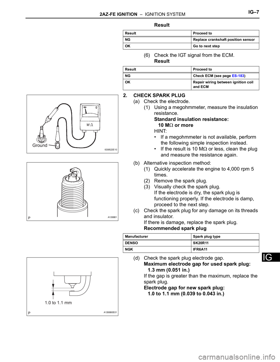
2. CHECK SPARK PLUG
(a) Check the electrode.
(1) Using a megohmmeter, measure the insulation
resistance.
Standard insulation resistance:
10 M
or more
HINT:
• If a megohmmeter is not available, perform
the following simple inspection instead.
• If the result is 10 M
or less, clean the plug
and measure the resistance again.
(b) Alternative inspection method:
(1) Quickly accelerate the engine to 4,000 rpm 5
times.
(2) Remove the spark plug.
(3) Visually check the spark plug.
If the electrode is dry, the spark plug is
functioning properly. If the electrode is damp,
proceed to the next step.
(c) Check the spark plug for any damage on its threads
and insulator.
If there is damage, replace the spark plug.
Recommended spark plug
(d) Check the spark plug electrode gap.
Maximum electrode gap for used spark plug:
1.3 mm (0.051 in.)
If the gap is greater than the maximum, replace the
spark plug.
Electrode gap for new spark plug:
1.0 to 1.1 mm (0.039 to 0.043 in.)
Result Proceed to
NG Replace crankshaft position sensor
OK Go to next step
Result Proceed to
NG Check ECM (see page ES-183)
OK Repair wiring between ignition coil
and ECM
I039522E10
A126881
Manufacturer Spark plug type
DENSO SK20R11
NGK IFR6A11
A126880E01