sensor TOYOTA RAV4 2006 Service Repair Manual
[x] Cancel search | Manufacturer: TOYOTA, Model Year: 2006, Model line: RAV4, Model: TOYOTA RAV4 2006Pages: 2000, PDF Size: 45.84 MB
Page 895 of 2000
2GR-FE IGNITION – IGNITION SYSTEMIG–5
IG
ON-VEHICLE INSPECTION
1. CHECK IGNITION COIL ASSEMBLY AND PERFORM
SPARK TEST
NOTICE:
In this section, the terms "Cold" and "Hot" refer to
the temperature of the sensor. "Cold" means
approximately -10 to 50
C (14 to 122F). "Hot" means
approximately 50 to 100
C (122 to 212F).
(a) Check the DTCs.
NOTICE:
If a DTC is present, perform troubleshooting in
accordance with the procedure for that DTC.
(b) Check that sparks occur.
(1) Remove the V-bank cover.
(2) Remove the intake air surge tank (see page
EM-27).
(3) Remove the bolt and ignition coil.
(4) Using a 16 mm spark plug wrench, remove the
spark plug.
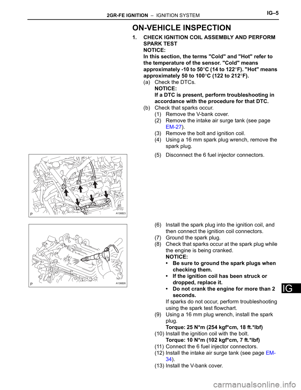
(5) Disconnect the 6 fuel injector connectors.
(6) Install the spark plug into the ignition coil, and
then connect the ignition coil connectors.
(7) Ground the spark plug.
(8) Check that sparks occur at the spark plug while
the engine is being cranked.
NOTICE:
• Be sure to ground the spark plugs when
checking them.
• If the ignition coil has been struck or
dropped, replace it.
• Do not crank the engine for more than 2
seconds.
If sparks do not occur, perform troubleshooting
using the spark test flowchart.
(9) Using a 16 mm plug wrench, install the spark
plug.
Torque: 25 N*m (254 kgf*cm, 18 ft.*lbf)
(10) Install the ignition coil with the bolt.
Torque: 10 N*m (102 kgf*cm, 7 ft.*lbf)
(11) Connect the 6 fuel injector connectors.
(12) Install the intake air surge tank (see page EM-
34).
(13) Install the V-bank cover.
A136823
A136826
Page 896 of 2000

IG–62GR-FE IGNITION – IGNITION SYSTEM
IG
(c) Perform troubleshooting using the spark test
flowchart.
(1) Check that the ignition coil connector is
securely connected.
Result
(2) Perform the spark test on each ignition coil.
1. Replace the ignition coil with a normal one.
2. Perform the spark test again.
Result
(3) Check the power supply to the ignition coil.
1. Disconnect the ignition coil connector.
2. Turn the ignition switch ON.
3. Measure the voltage of the wire harness
side connector.
Standard voltage
Result
(4) Check the resistance of the crankshaft position
sensor.
Standard resistance
Result
(5) Check the IGT signal from the ECM.
Result
Result Proceed to
NG Connect securely
OK Go to next step
Result Proceed to
OK Replace ignition coil
NG Go to next step
A136824
Tester Connection Specified Condition
1 (+B) - 4 (GND) 9 to 14 V
Result Proceed to
NG Check wire harness and connector
OK Go to next step
Temperature Condition Specified Condition
Cold 1,630 to 2,740
Hot 2,065 to 3,225
Result Proceed to
NG Replace crankshaft position sensor
OK Go to next step
Result Proceed to
NG Check ECM (see page ES-220)
OK Repair wiring between ignition coil and
ECM
Page 926 of 2000
2AZ-FE CHARGING – GENERATORCH–15
CH
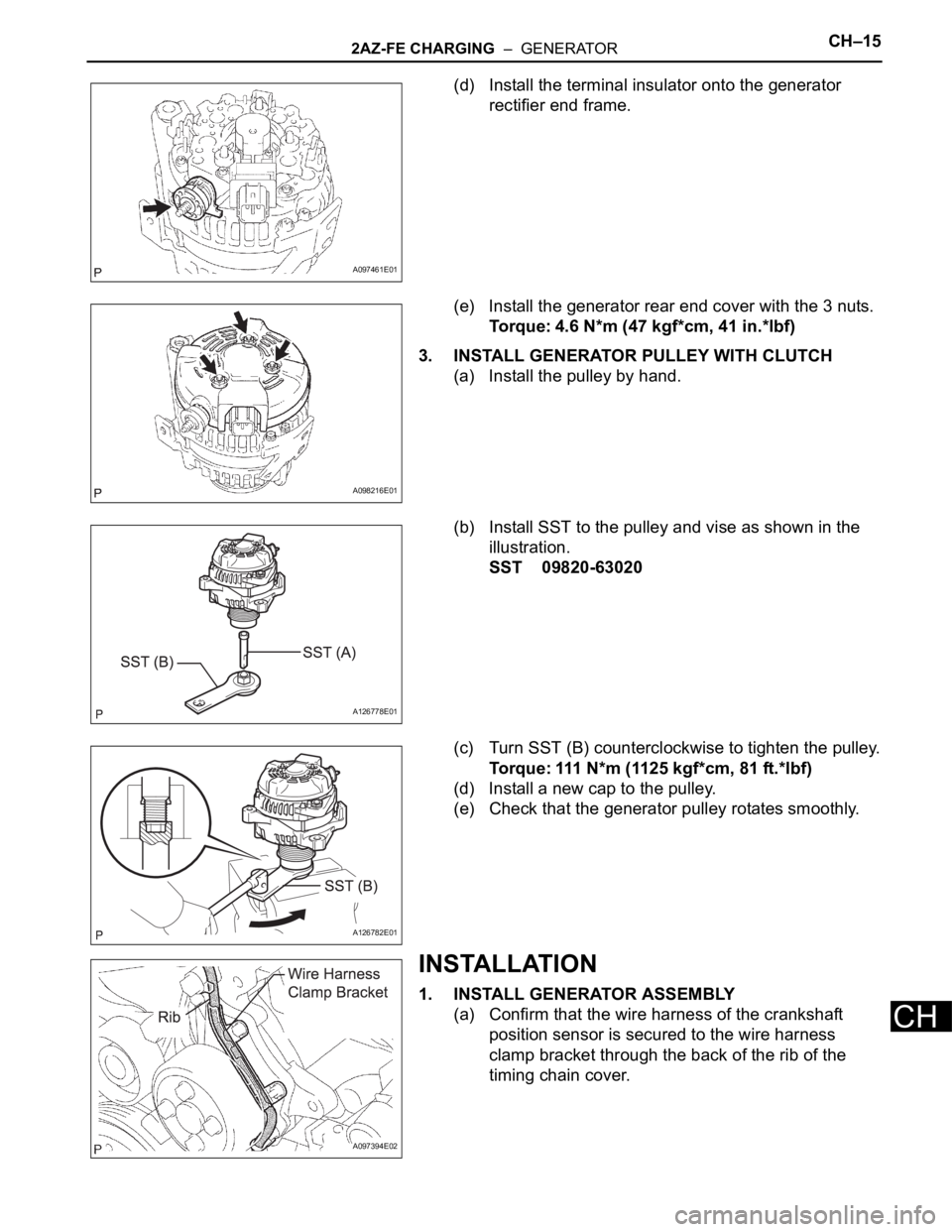
(d) Install the terminal insulator onto the generator
rectifier end frame.
(e) Install the generator rear end cover with the 3 nuts.
Torque: 4.6 N*m (47 kgf*cm, 41 in.*lbf)
3. INSTALL GENERATOR PULLEY WITH CLUTCH
(a) Install the pulley by hand.
(b) Install SST to the pulley and vise as shown in the
illustration.
SST 09820-63020
(c) Turn SST (B) counterclockwise to tighten the pulley.
Torque: 111 N*m (1125 kgf*cm, 81 ft.*lbf)
(d) Install a new cap to the pulley.
(e) Check that the generator pulley rotates smoothly.
INSTALLATION
1. INSTALL GENERATOR ASSEMBLY
(a) Confirm that the wire harness of the crankshaft
position sensor is secured to the wire harness
clamp bracket through the back of the rib of the
timing chain cover.
A097461E01
A098216E01
A126778E01
A126782E01
A097394E02
Page 959 of 2000

U140F AUTOMATIC TRANSAXLE – AUTOMATIC TRANSAXLE SYSTEMAX–25
AX
HINT:
*: Drive at such a speed in the uppermost gear to engage
lock-up. The vehicle can be driven at a speed lower than the
speed shown in the above diagram under the lock-up
condition.
NOTICE:
It is necessary to drive the vehicle for approximately 30
minutes to detect DTC P0711 (Transmission fluid
temperature sensor "A" performance).
C115866E05
Page 960 of 2000

AX–26U140F AUTOMATIC TRANSAXLE – AUTOMATIC TRANSAXLE SYSTEM
AX
PROBLEM SYMPTOMS TABLE
HINT:
• Use the table below to help determine the cause of the
problem symptom. The potential causes of the symptoms
are listed in order of probability in the "Suspected area"
column of the table. Check each symptom by checking the
suspected areas in the order they are listed. Replace parts
as necessary.
• The Matrix Chart is divided into 2 chapters. When
troubleshooting, check Chapter 1 first. If instructions are
given in Chapter 1 to proceed to 2, proceed as instructed.
• If the instruction "Proceed to next circuit inspection shown
in problem symptoms table" is given in the flowchart for
each circuit, proceed to the next suspected area in the
table.
• If the problem still occurs even though there are no
malfunctions in any of the circuits, check the ECM and
replace it if necessary.
CHAPTER 1: ELECTRICAL CIRCUIT MATRIX CHART
HINT:
*: When the circuit is defective, a DTC may be output.
CHAPTER 2: ON-VEHICLE REPAIR AND OFF-VEHICLE REPAIR
Symptom Suspected area See page
No up-shift (1st -> 2nd) ECMIN-37
No up-shift (2nd -> 3rd) ECMIN-37
No up-shift (3rd -> O/D)1. Park/Neutral position switch circuit*AX-39
2. ECMIN-37
No down-shift (O/D -> 3rd) ECMIN-37
No down-shift (3rd -> 2nd) ECMIN-37
No down-shift (2nd -> 1st) ECMIN-37
No lock-up or no lock-up off ECMIN-37
Shift point too high or too low ECMIN-37
Up-shift to O/D from 3rd while shift lever is on 31. Park/Neutral position switch circuit*AX-39
2. ECMIN-37
Up-shift to O/D from 3rd while engine is cold1. Engine coolant temp. sensor circuit*ES-51
2. ECMIN-37
Harsh engagement (N -> D) ECMIN-37
Harsh engagement (lock-up) ECMIN-37
Harsh engagement (any driving position) ECMIN-37
Poor acceleration ECMIN-37
Engine stalls when starting off or stopping ECMIN-37
Malfunction in shifting1. Park/Neutral position switch circuit*AX-39
2. ECMIN-37
Symptom Suspected area See page
Vehicle does not move in all positions other than P and
N1. Manual valveAX-155
2. Primary regulator valveAX-155
3. Front and rear planetary gearAX-155
4. U/D planetary gearAX-155
5. F2 U/D one-way clutchAX-155
6. C1 forward clutchAX-155
7. B3 U/D brakeAX-155
Page 964 of 2000

AX–30U140F AUTOMATIC TRANSAXLE – AUTOMATIC TRANSAXLE SYSTEM
AX
3 (A9-26) - E1 (B30-104) P - BR 3 shift position switch
signalIgnition switch ON and
transfer shift lever on 310 to 14 V
3 (A9-26) - E1 (B30-104) P - BR 3 shift position switch
signalIgnition switch ON and
transfer shift lever not on 3Below 1 V
2 (B30-55) - E1 (B30-104) P - BR 2 shift position switch
signalIgnition switch ON and
transfer shift lever on 2
and L10 to 14 V
2 (B30-55) - E1 (B30-104) P - BR 2 shift position switch
signalIgnition switch ON and
transfer shift lever not on 2
and LBelow 1 V
L (B30-74) - E1 (B30-104) LG - BR L shift position switch
signalIgnition switch ON and
transfer shift lever on L10 to 14 V
L (B30-74) - E1 (B30-104) LG - BR L shift position switch
signalIgnition switch ON and
transfer shift lever not on LBelow 1 V
STP (A9-36) - E1 (B30-
104)L - BR Stop light switch signal Brake pedal is depressed Between 10 V and 14 V
STP (A9-36) - E1 (B30-
104)L - BR Stop light switch signal Brake pedal is released Below 1 V
SL1+ (B30-57) - SL1-
(B30-77)V - P SL1 solenoid signal Engine idle speed Pulse generation
(see waveform 1)
SL1+ (B30-57) - SL1-
(B30-77)V - P SL1 solenoid signal Ignition switch ON Pulse generation
(see waveform 1)
SL1+ (B30-57) - SL1-
(B30-77)V - P SL1 solenoid signal 1st gear Pulse generation
(see waveform 1)
SL1+ (B30-57) - SL1-
(B30-77)V - P SL1 solenoid signal Not on 1st gear Below 1 V
SL2+ (B30-58) - SL2-
(B30-59)Y - L SL2 solenoid signal Engine idle speed Pulse generation
(see waveform 2)
SL2+ (B30-58) - SL2-
(B30-59)Y - L SL2 solenoid signal Ignition switch ON Pulse generation
(see waveform 2)
SL2+ (B30-58) - SL2-
(B30-59)Y - L SL2 solenoid signal 1st or 2nd gear Pulse generation
(see waveform 2)
SL2+ (B30-58) - SL2-
(B30-59)Y - L SL2 solenoid signal 3rd or O/D gear Below 1 V
DSL (B30-79) - E01 (B30-
45)G - BR DSL solenoid signal Vehicle speed 65 km/h (40
mph), lock-up (ON to OFF)Below 1 V
DSL (B30-79) - E01 (B30-
45)G - BR DSL solenoid signal Vehicle driving under lock-
up positionPulse generation
(see waveform 3)
SLT+ (B30-76) - SLT-
(B30-75)R - GR SLT solenoid signal Engine idle speed Pulse generation
(see waveform 4)
S4 (B30-78) - E01 (B30-
45)W - BR S4 solenoid signal Ignition switch ON Below 1 V
S4 (B30-78) - E01 (B30-
45)W - BR S4 solenoid signal O/D gear 10 to 14 V
S4 (B30-78) - E01 (B30-
45)W - BR S4 solenoid signal Not on O/D gear Below 1 V
THO1 (B30-72) - ETHO
(B30-95)LG- BR ATF temperature sensor
signalATF temperature: 115
C
(239F) or moreBelow 1.5 V
NT+ (B30-125) - NT- (B30-
124)W - R Speed sensor (NT) signal Vehicle speed 20 km/h (12
mph)Pulse generation
(see waveform 5)
NC+ (B30-101) - NC-
(B30-102)R - W Speed sensor (NC) signal Vehicle speed 30 km/h (19
mph): (3rd gear)
Engine speed 1,400 rpmPulse generation
(see waveform 6) Symbols (Terminal No.) Wiring Color Terminal Description ConditionSpecified Condition
Page 980 of 2000

AX–152U140F AUTOMATIC TRANSAXLE – AUTOMATIC TRANSAXLE ASSEMBLY
AX
9. INSTALL ENGINE MOUNTING BRACKET RR
(a) Install the mounting bracket with the 3 bolts.
Torque: 45 N*m (459 kgf*cm, 33 ft.*lbf)
10. INSTALL TRANSMISSION OIL COOLER
(a) Install the oil cooler (see page AX-127).
11. CONNECT WIRE HARNESS
(a) Connect the wire harness clamps.
(b) Connect the 2 speed sensor connectors.
(c) Connect the transaxle wire connector.
(d) Connect the park/neutral position switch connector.
12. INSTALL STARTER ASSEMBLY
(a) Install the starter with the 2 bolts.
Torque: 37 N*m (377 kgf*cm, 27 ft.*lbf)
(b) Connect the starter wire with the nut.
Torque: 13 N*m (133 kgf*cm, 10 ft.*lbf)
(c) Connect the starter connector.
(d) Install the terminal nut and cover the nut with the
cap.
Torque: 9.8 N*m (100 kgf*cm, 7 in.*lbf)
13. INSTALL ENGINE ASSEMBLY WITH TRANSAXLE
(a) Install the engine with transaxle. (see page EM-
105).
14. ADD AUTOMATIC TRANSAXLE FLUID
Fluid type:
Toyota Genuine ATF WS
15. INSPECT AUTOMATIC TRANSAXLE FLUID
(a) Inspect the automatic transaxle fluid (see page AX-
102).
16. PERFORM RESET MEMORY
(a) Perform the RESET MEMORY procedures (A/T
initialization) (see page AX-18).
C130913
C127821
A124921
A124920
Page 1006 of 2000
AX–212U140F AUTOMATIC TRANSAXLE – AUTOMATIC TRANSAXLE UNIT
AX
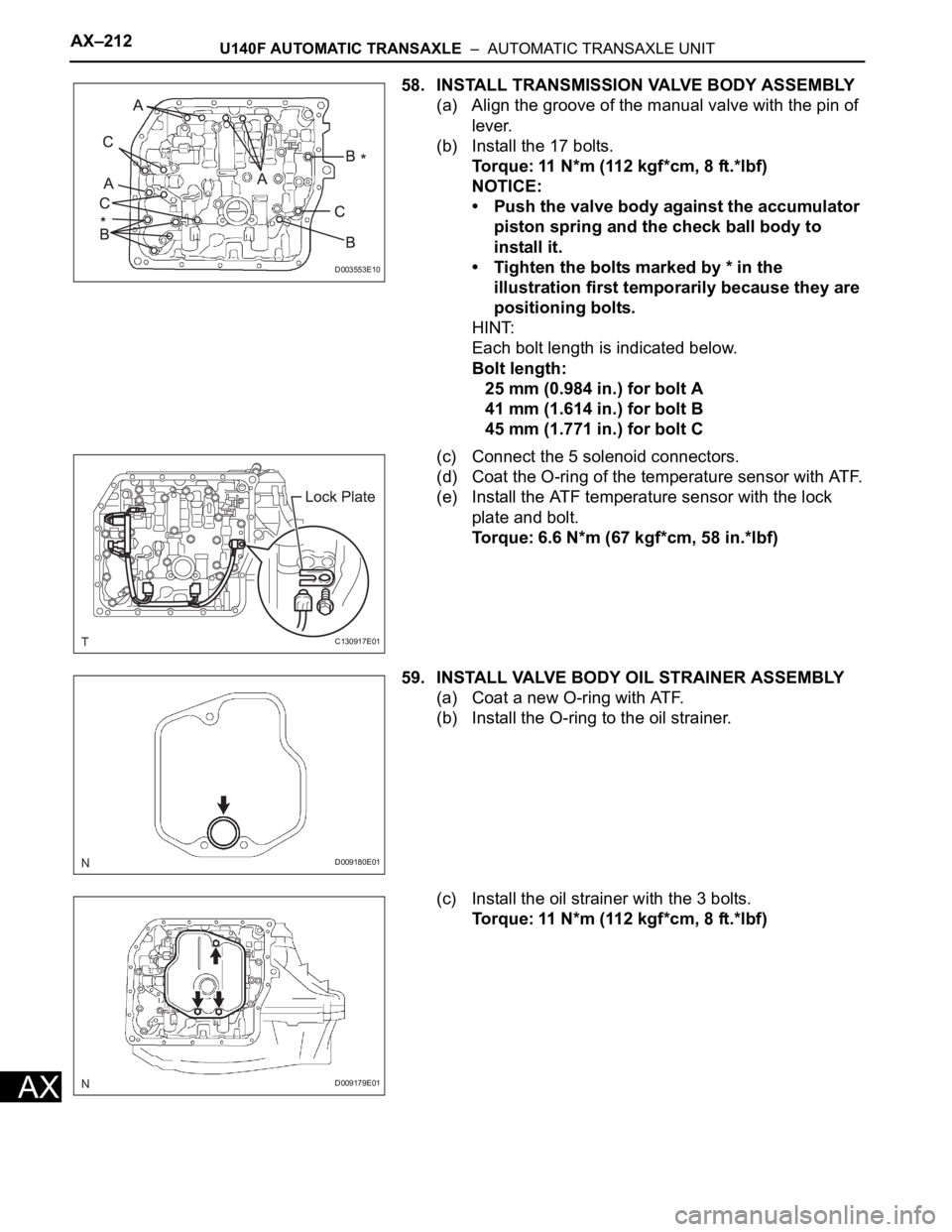
58. INSTALL TRANSMISSION VALVE BODY ASSEMBLY
(a) Align the groove of the manual valve with the pin of
lever.
(b) Install the 17 bolts.
Torque: 11 N*m (112 kgf*cm, 8 ft.*lbf)
NOTICE:
• Push the valve body against the accumulator
piston spring and the check ball body to
install it.
• Tighten the bolts marked by * in the
illustration first temporarily because they are
positioning bolts.
HINT:
Each bolt length is indicated below.
Bolt length:
25 mm (0.984 in.) for bolt A
41 mm (1.614 in.) for bolt B
45 mm (1.771 in.) for bolt C
(c) Connect the 5 solenoid connectors.
(d) Coat the O-ring of the temperature sensor with ATF.
(e) Install the ATF temperature sensor with the lock
plate and bolt.
Torque: 6.6 N*m (67 kgf*cm, 58 in.*lbf)
59. INSTALL VALVE BODY OIL STRAINER ASSEMBLY
(a) Coat a new O-ring with ATF.
(b) Install the O-ring to the oil strainer.
(c) Install the oil strainer with the 3 bolts.
Torque: 11 N*m (112 kgf*cm, 8 ft.*lbf)
D003553E10
C130917E01
D009180E01
D009179E01
Page 1007 of 2000
U140F AUTOMATIC TRANSAXLE – AUTOMATIC TRANSAXLE UNITAX–213
AX
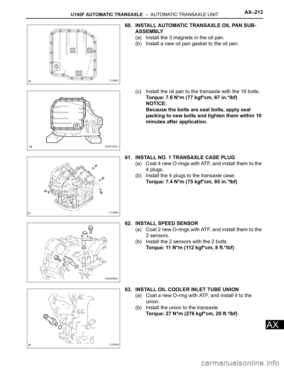
60. INSTALL AUTOMATIC TRANSAXLE OIL PAN SUB-
ASSEMBLY
(a) Install the 3 magnets in the oil pan.
(b) Install a new oil pan gasket to the oil pan.
(c) Install the oil pan to the transaxle with the 18 bolts.
Torque: 7.6 N*m (77 kgf*cm, 67 in.*lbf)
NOTICE:
Because the bolts are seal bolts, apply seal
packing to new bolts and tighten them within 10
minutes after application.
61. INSTALL NO. 1 TRANSAXLE CASE PLUG
(a) Coat 4 new O-rings with ATF, and install them to the
4 plugs.
(b) Install the 4 plugs to the transaxle case.
Torque: 7.4 N*m (75 kgf*cm, 65 in.*lbf)
62. INSTALL SPEED SENSOR
(a) Coat 2 new O-rings with ATF, and install them to the
2 sensors.
(b) Install the 2 sensors with the 2 bolts.
Torque: 11 N*m (112 kgf*cm, 8 ft.*lbf)
63. INSTALL OIL COOLER INLET TUBE UNION
(a) Coat a new O-ring with ATF, and install it to the
union.
(b) Install the union to the transaxle.
Torque: 27 N*m (276 kgf*cm, 20 ft.*lbf)
C134981
D009176E01
C134982
D003900E01
C126599
Page 1042 of 2000
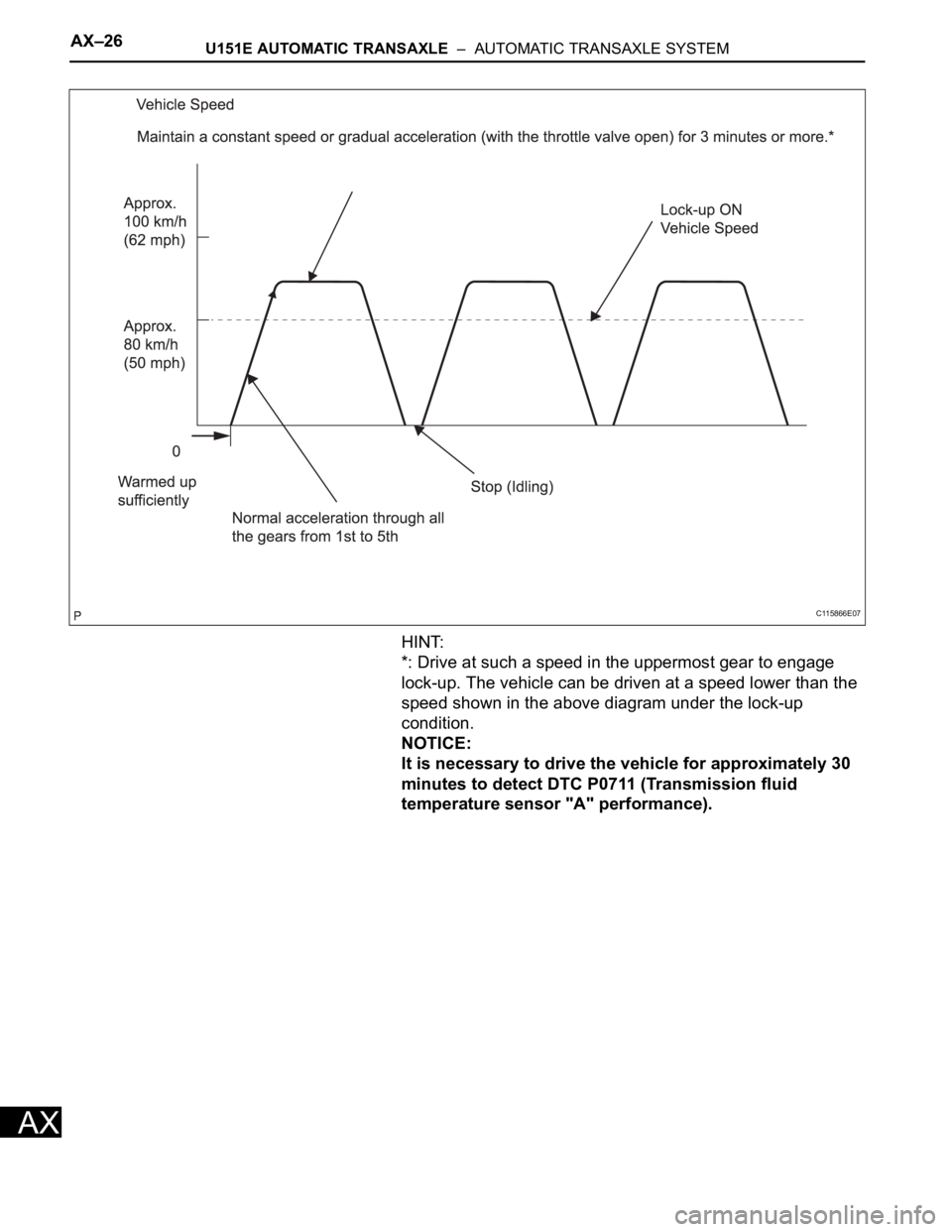
AX–26U151E AUTOMATIC TRANSAXLE – AUTOMATIC TRANSAXLE SYSTEM
AX
HINT:
*: Drive at such a speed in the uppermost gear to engage
lock-up. The vehicle can be driven at a speed lower than the
speed shown in the above diagram under the lock-up
condition.
NOTICE:
It is necessary to drive the vehicle for approximately 30
minutes to detect DTC P0711 (Transmission fluid
temperature sensor "A" performance).
C115866E07