abs sensor TOYOTA RAV4 2006 Service User Guide
[x] Cancel search | Manufacturer: TOYOTA, Model Year: 2006, Model line: RAV4, Model: TOYOTA RAV4 2006Pages: 2000, PDF Size: 45.84 MB
Page 1459 of 2000
AXLE – REAR AXLE HUB AND BEARINGAH–19
AH
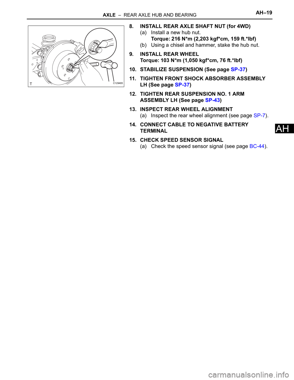
8. INSTALL REAR AXLE SHAFT NUT (for 4WD)
(a) Install a new hub nut.
Torque: 216 N*m (2,203 kgf*cm, 159 ft.*lbf)
(b) Using a chisel and hammer, stake the hub nut.
9. INSTALL REAR WHEEL
Torque: 103 N*m (1,050 kgf*cm, 76 ft.*lbf)
10. STABILIZE SUSPENSION (See page SP-37)
11. TIGHTEN FRONT SHOCK ABSORBER ASSEMBLY
LH (See page SP-37)
12. TIGHTEN REAR SUSPENSION NO. 1 ARM
ASSEMBLY LH (See page SP-43)
13. INSPECT REAR WHEEL ALIGNMENT
(a) Inspect the rear wheel alignment (see page SP-7).
14. CONNECT CABLE TO NEGATIVE BATTERY
TERMINAL
15. CHECK SPEED SENSOR SIGNAL
(a) Check the speed sensor signal (see page BC-44).
C129485
Page 1460 of 2000
SP–14SUSPENSION – FRONT SHOCK ABSORBER WITH COIL SPRING
SP
INSTALLATION
HINT:
• Use the same procedures for the RH side and LH side.
• The procedures listed below are for the LH side.
1. INSTALL FRONT SHOCK ABSORBER WITH COIL
SPRING LH
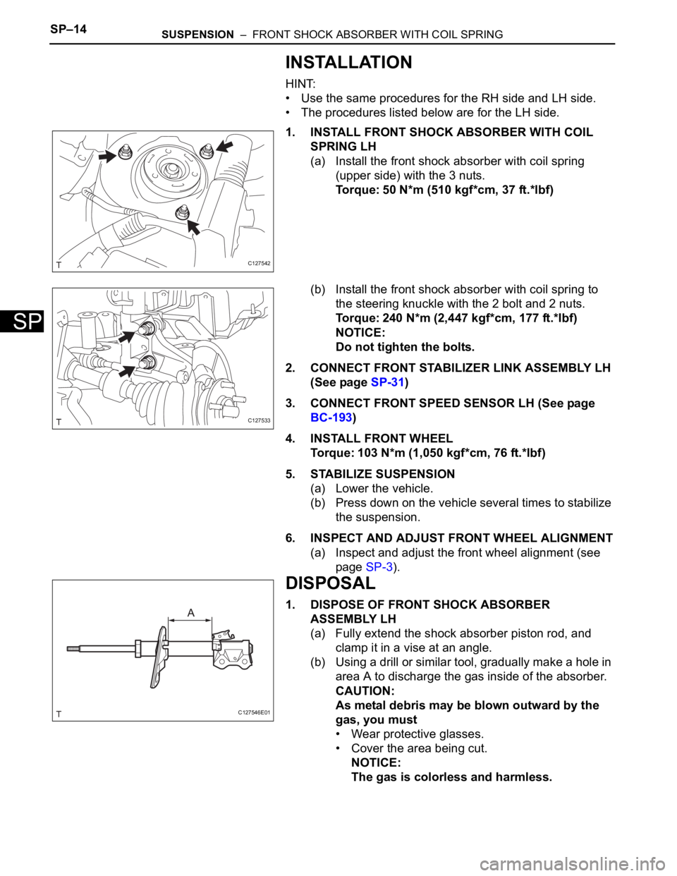
(a) Install the front shock absorber with coil spring
(upper side) with the 3 nuts.
Torque: 50 N*m (510 kgf*cm, 37 ft.*lbf)
(b) Install the front shock absorber with coil spring to
the steering knuckle with the 2 bolt and 2 nuts.
Torque: 240 N*m (2,447 kgf*cm, 177 ft.*lbf)
NOTICE:
Do not tighten the bolts.
2. CONNECT FRONT STABILIZER LINK ASSEMBLY LH
(See page SP-31)
3. CONNECT FRONT SPEED SENSOR LH (See page
BC-193)
4. INSTALL FRONT WHEEL
Torque: 103 N*m (1,050 kgf*cm, 76 ft.*lbf)
5. STABILIZE SUSPENSION
(a) Lower the vehicle.
(b) Press down on the vehicle several times to stabilize
the suspension.
6. INSPECT AND ADJUST FRONT WHEEL ALIGNMENT
(a) Inspect and adjust the front wheel alignment (see
page SP-3).
DISPOSAL
1. DISPOSE OF FRONT SHOCK ABSORBER
ASSEMBLY LH
(a) Fully extend the shock absorber piston rod, and
clamp it in a vise at an angle.
(b) Using a drill or similar tool, gradually make a hole in
area A to discharge the gas inside of the absorber.
CAUTION:
As metal debris may be blown outward by the
gas, you must
• Wear protective glasses.
• Cover the area being cut.
NOTICE:
The gas is colorless and harmless.
C127542
C127533
C127546E01
Page 1465 of 2000
SP–20SUSPENSION – FRONT SHOCK ABSORBER WITH COIL SPRING (for Sport Package)
SP
INSTALLATION
HINT:
• Use the same procedures for the RH side and LH side.
• The procedures listed below are for the LH side.
1. INSTALL FRONT SHOCK ABSORBER WITH COIL
SPRING
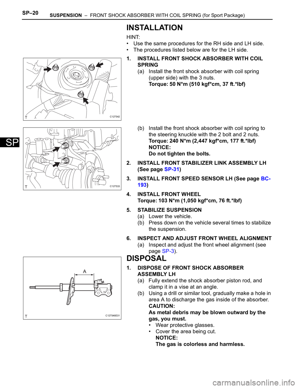
(a) Install the front shock absorber with coil spring
(upper side) with the 3 nuts.
Torque: 50 N*m (510 kgf*cm, 37 ft.*lbf)
(b) Install the front shock absorber with coil spring to
the steering knuckle with the 2 bolt and 2 nuts.
Torque: 240 N*m (2,447 kgf*cm, 177 ft.*lbf)
NOTICE:
Do not tighten the bolts.
2. INSTALL FRONT STABILIZER LINK ASSEMBLY LH
(See page SP-31)
3. INSTALL FRONT SPEED SENSOR LH (See page BC-
193)
4. INSTALL FRONT WHEEL
Torque: 103 N*m (1,050 kgf*cm, 76 ft.*lbf)
5. STABILIZE SUSPENSION
(a) Lower the vehicle.
(b) Press down on the vehicle several times to stabilize
the suspension.
6. INSPECT AND ADJUST FRONT WHEEL ALIGNMENT
(a) Inspect and adjust the front wheel alignment (see
page SP-3).
DISPOSAL
1. DISPOSE OF FRONT SHOCK ABSORBER
ASSEMBLY LH
(a) Fully extend the shock absorber piston rod, and
clamp it in a vise at an angle.
(b) Using a drill or similar tool, gradually make a hole in
area A to discharge the gas inside of the absorber.
CAUTION:
As metal debris may be blown outward by the
gas, you must.
• Wear protective glasses.
• Cover the area being cut.
NOTICE:
The gas is colorless and harmless.
C127542
C127533
C127546E01
Page 1509 of 2000
BC–6BRAKE CONTROL – VEHICLE STABILITY CONTROL SYSTEM
BC
SYSTEM DESCRIPTION
1. SYSTEM DESCRIPTION
HINT:
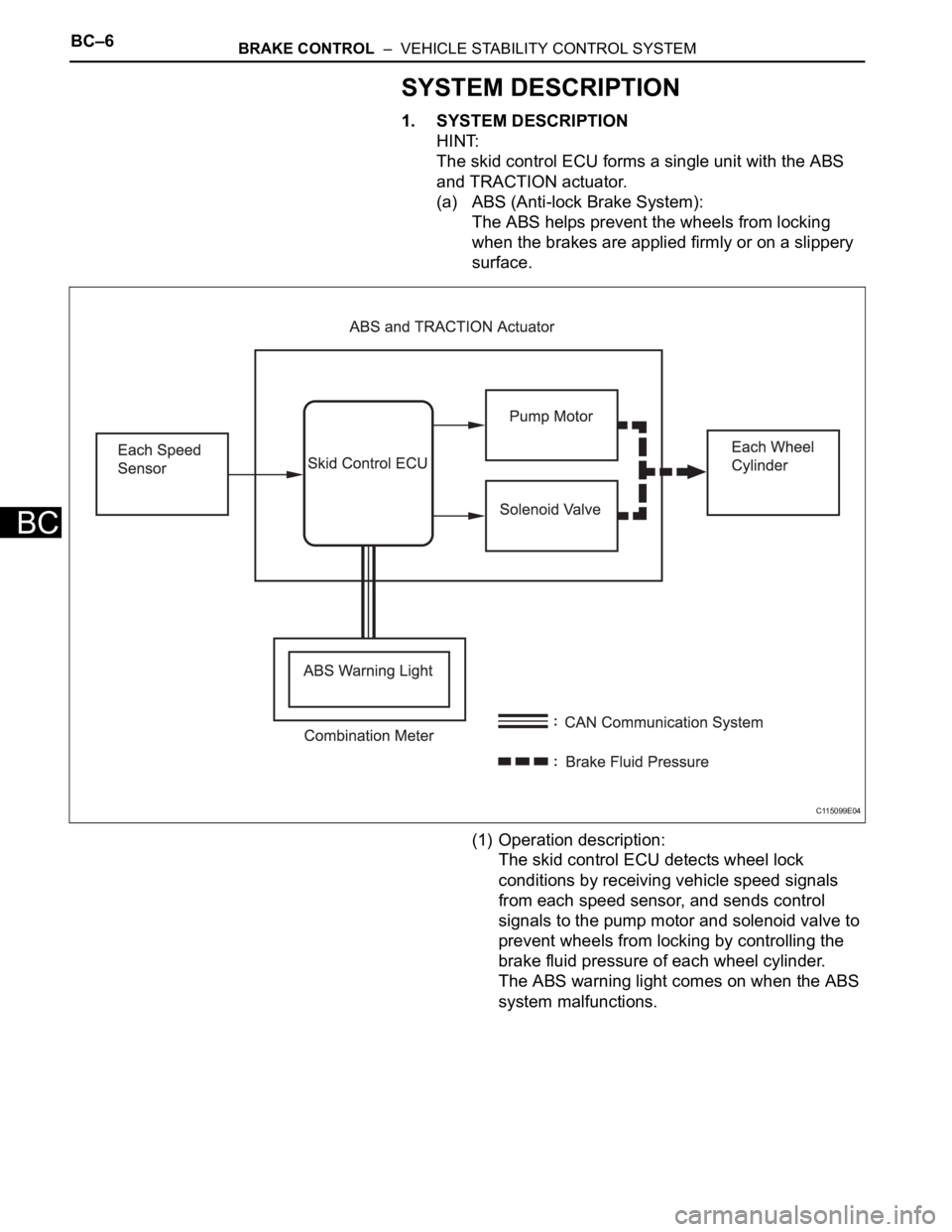
The skid control ECU forms a single unit with the ABS
and TRACTION actuator.
(a) ABS (Anti-lock Brake System):
The ABS helps prevent the wheels from locking
when the brakes are applied firmly or on a slippery
surface.
(1) Operation description:
The skid control ECU detects wheel lock
conditions by receiving vehicle speed signals
from each speed sensor, and sends control
signals to the pump motor and solenoid valve to
prevent wheels from locking by controlling the
brake fluid pressure of each wheel cylinder.
The ABS warning light comes on when the ABS
system malfunctions.
C115099E04
Page 1510 of 2000
BRAKE CONTROL – VEHICLE STABILITY CONTROL SYSTEMBC–7
BC
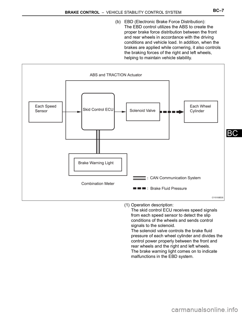
(b) EBD (Electronic Brake Force Distribution):
The EBD control utilizes the ABS to create the
proper brake force distribution between the front
and rear wheels in accordance with the driving
conditions and vehicle load. In addition, when the
brakes are applied while cornering, it also controls
the braking forces of the right and left wheels,
helping to maintain vehicle stability.
(1) Operation description:
The skid control ECU receives speed signals
from each speed sensor to detect the slip
conditions of the wheels and sends control
signals to the solenoid.
The solenoid valve controls the brake fluid
pressure of each wheel cylinder and divides the
control power properly between the front and
rear wheels and the right and left wheels.
The brake warning light comes on to indicate
malfunctions in the EBD system.
C115100E05
Page 1511 of 2000
BC–8BRAKE CONTROL – VEHICLE STABILITY CONTROL SYSTEM
BC
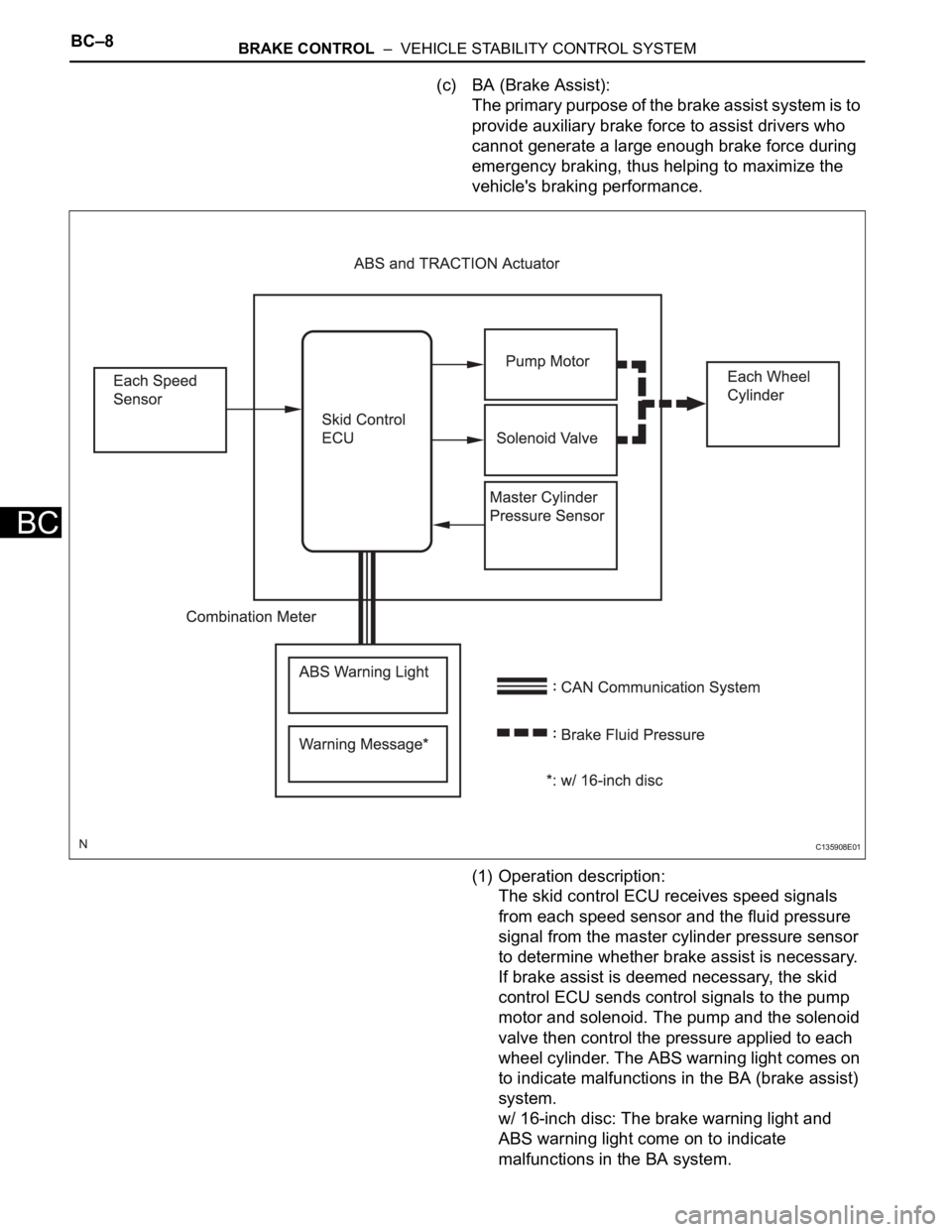
(c) BA (Brake Assist):
The primary purpose of the brake assist system is to
provide auxiliary brake force to assist drivers who
cannot generate a large enough brake force during
emergency braking, thus helping to maximize the
vehicle's braking performance.
(1) Operation description:
The skid control ECU receives speed signals
from each speed sensor and the fluid pressure
signal from the master cylinder pressure sensor
to determine whether brake assist is necessary.
If brake assist is deemed necessary, the skid
control ECU sends control signals to the pump
motor and solenoid. The pump and the solenoid
valve then control the pressure applied to each
wheel cylinder. The ABS warning light comes on
to indicate malfunctions in the BA (brake assist)
system.
w/ 16-inch disc: The brake warning light and
ABS warning light come on to indicate
malfunctions in the BA system.
C135908E01
Page 1521 of 2000

BC–18BRAKE CONTROL – VEHICLE STABILITY CONTROL SYSTEM
BC
(3) Front Wheel Skid Tendency
When the skid control ECU determines that
there is a front wheel skid tendency, it controls
the VSC to dampen the front wheel skid. At the
same time, it effects cooperative control with the
EPS to provide steering torque assist, which
facilitates the driver's steering maneuvers to
stabilize the vehicle posture. To prevent
excessive steering maneuvers, it provides a
steering torque assist. This assist increases the
resistance to counter the driver's steering effort,
if the driver turns the steering wheel excessively.
(4) Rear Wheel Skid Tendency
When the skid control ECU determines that
there is a rear wheel skid tendency, it controls
the VSC to dampen the rear wheel skid. At the
same time, it effects cooperative control with the
EPS to provide steering torque assist, which
facilitates the driver's steering maneuvers in the
direction to correct the rear wheel skid.
(5) Acceleration During Cornering
A sudden acceleration of the vehicle during
cornering may cause a drive wheel to freewheel,
which could cause the front wheels or rear
wheels to skid. If the skid control ECU
determines that there is freewheeling of a drive
wheel, a front wheel skid tendency, or a rear
wheel skid tendency, it effects cooperative
control with the 4WD system to optimally control
the drive torque distribution to the front and rear
wheels. Furthermore, it controls the TRC and
the VSC as needed to ensure driving stability
and acceleration performance.
(b) Operation
The operation of the solenoid valves under the
cooperative control is the same as the TRC or VSC
operation.
3. ABS WITH EBD, BA, TRC AND VSC OPERATION
(a) The skid control ECU calculates vehicle stability
tendency based on the signals from the 4 wheel
speed sensors, the yaw rate and deceleration
sensor and the steering sensor. In addition, it
evaluates the results of the calculations to
determine whether any control actions (control of
the engine output torque by electronic throttle
control and of the brake fluid pressure by the ABS
and TRACTION actuator) should be implemented.
(b) The slip indicator blinks and the skid control buzzer
sounds to inform the driver that the VSC system is
operating. The slip indicator also blinks when
traction control is operating, and the operation being
performed is displayed.
Page 1522 of 2000

BRAKE CONTROL – VEHICLE STABILITY CONTROL SYSTEMBC–19
BC
4. FAIL SAFE FUNCTION
(a) When a failure occurs in the ABS with BA, TRC and
VSC systems, the ABS and VSC warning lights
illuminate, the slip indicator light comes on*1 or
remains off*2, and the operations of those systems
are prohibited. In addition to this, when a failure
which disables the EBD operation occurs, the brake
warning light comes on and its operation is
prohibited.
HINT:
*1: for 2WD
*2: for 4WD
(b) If control is prohibited due to a malfunction during
operation, control is disabled gradually to avoid
sudden vehicle instability.
5. INITIAL CHECK
(a) When the vehicle speed first reaches approximately
6 km/h (4 mph) or more after the ignition switch is
turned ON, each solenoid valve and the motor of the
ABS and TRACTION actuator are sequentially
activated to perform electrical checks. During the
initial check, the operating sound of the solenoid
valve and motor can be heard from the engine
compartment, but this does not indicate a
malfunction.
6. SERVICE MODE
(a) VSC operation can be disabled by operating the
intelligent tester.
HINT:
Refer to the intelligent tester operator's manual for
further details.
7. FUNCTION OF COMPONENTS
Components Functions
Speed Sensor
(Semiconductor Type)Detects the wheel speed and sends the signal to skid
control ECU
Skid Control ECU
(Housed in ABS and TRACTION Actuator)• Processes the signals from each sensor to control the
ABS, BA, TRC, and VSC
• Sends and receives control signals to and from the
ECM, yaw rate and deceleration sensor, steering
sensor, etc. via CAN communication.
ABS and TRACTION Actuator • Consists of the master cylinder cut solenoid valve,
holding solenoid valve, pressure reduction solenoid
valve, pump motor, and reservoir, and adjusts the brake
fluid pressure applied to each wheel cylinder
• Houses the skid control ECU
Solenoid Relay • Supplies power to each solenoid
• Housed in the skid control ECU
Motor Relay (VSC MTR Relay) • Supplies power to the pump motor
• Installed in engine room No. 1 relay block
Fail-safe Relay (VSC FAIL Relay) • Cuts off power to the motor when the pump motor circuit
malfunctions
• Installed in engine room No. 1 relay block
Page 1523 of 2000

BC–20BRAKE CONTROL – VEHICLE STABILITY CONTROL SYSTEM
BC
HINT:
*1: w/ Downhill assist control
*2: for 2WD w/ AUTO LSD
Steering Sensor • Detects the steering extent and direction and sends
signals to the skid control ECU via CAN communication
• Has a magnetic resistance element which detects the
rotation of the magnet housed in the detection gear in
order to detect the changes in magnetic resistance and
the steering amount and direction
Yaw Rate and Deceleration Sensor • Yaw rate sensor detects the vehicle's angular velocity
(yaw rate) in the vertical direction based on the extent
and direction of the deflection of the piezoelectric
ceramics
• Deceleration sensor measures the capacity of the
condenser that changes the distance between the
electrodes depending on G force, which occurs when
the vehicle is accelerated, and converts the measured
value into electrical signals
• Sends signals to the skid control ECU via CAN
communication
Master Cylinder Pressure Sensor • Detects the brake fluid pressure in the master cylinder
• Housed in the ABS and TRACTION actuator
ECM• Controls the engine output when TRC and VSC are
operating with the skid control ECU via CAN
communication
Downhill Assist Control switch*1 Allows the driver to turn downhill assist control ON and OFF
AUTO LSD switch*2 Allows the driver to turn AUTO LSD ON and OFF
Combination Meter ABS Warning Light • Illuminates to inform the driver that a malfunction in the
ABS has occurred
• Blinks to indicate DTCs that relate to the ABS
VSC Warning Light • Illuminates to inform the driver that a malfunction in the
VSC system has occurred
• Blinks to indicate DTCs that relate to the VSC
Brake Warning light • Illuminates to inform the driver that the parking brake is
ON when the system is normal, and when the brake
fluid has decreased
• Illuminates to inform the driver that a malfunction in the
EBD has occurred
Slip Indicator Light • Blinks to inform the driver that TRC, VSC, downhill
assist control and hill-start assist control are operating
• Illuminates to inform the driver that a malfunction has
occurred in the TRC or VSC system
AUTO LSD Indicator Light*2 Lights up to inform the driver when AUTO LSD operation is
possible
Downhill Assist Control Indicator
Light*1Lights up to inform the driver when downhill assist control
operation is possible
Skid Control Buzzer • Intermittently sounds to inform the driver that the VSC is
operating
• Housed in the combination meter Components Functions
Page 1534 of 2000
BRAKE CONTROL – VEHICLE STABILITY CONTROL SYSTEMBC–31
BC
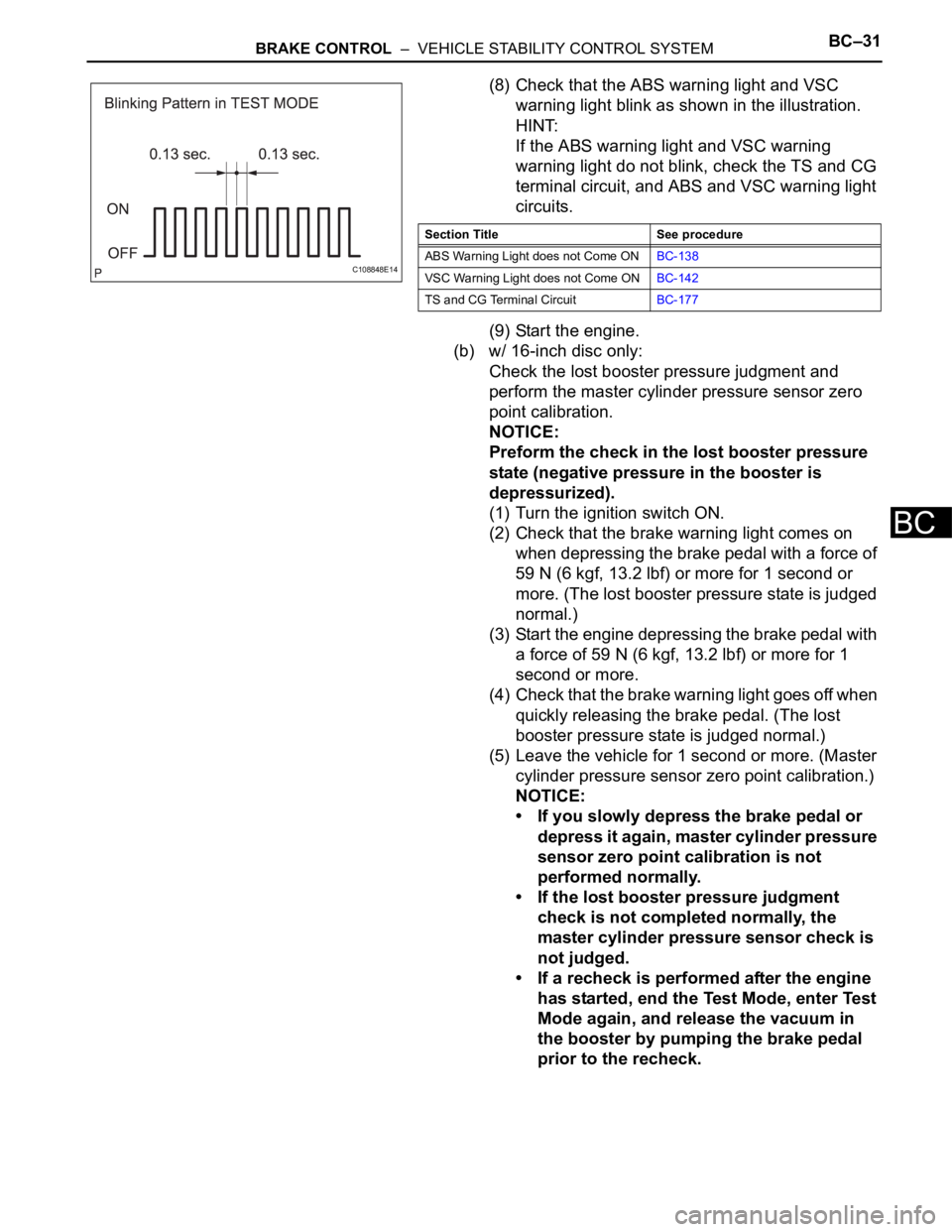
(8) Check that the ABS warning light and VSC
warning light blink as shown in the illustration.
HINT:
If the ABS warning light and VSC warning
warning light do not blink, check the TS and CG
terminal circuit, and ABS and VSC warning light
circuits.
(9) Start the engine.
(b) w/ 16-inch disc only:
Check the lost booster pressure judgment and
perform the master cylinder pressure sensor zero
point calibration.
NOTICE:
Preform the check in the lost booster pressure
state (negative pressure in the booster is
depressurized).
(1) Turn the ignition switch ON.
(2) Check that the brake warning light comes on
when depressing the brake pedal with a force of
59 N (6 kgf, 13.2 lbf) or more for 1 second or
more. (The lost booster pressure state is judged
normal.)
(3) Start the engine depressing the brake pedal with
a force of 59 N (6 kgf, 13.2 lbf) or more for 1
second or more.
(4) Check that the brake warning light goes off when
quickly releasing the brake pedal. (The lost
booster pressure state is judged normal.)
(5) Leave the vehicle for 1 second or more. (Master
cylinder pressure sensor zero point calibration.)
NOTICE:
• If you slowly depress the brake pedal or
depress it again, master cylinder pressure
sensor zero point calibration is not
performed normally.
• If the lost booster pressure judgment
check is not completed normally, the
master cylinder pressure sensor check is
not judged.
• If a recheck is performed after the engine
has started, end the Test Mode, enter Test
Mode again, and release the vacuum in
the booster by pumping the brake pedal
prior to the recheck.
C108848E14
Section Title See procedure
ABS Warning Light does not Come ONBC-138
VSC Warning Light does not Come ONBC-142
TS and CG Terminal CircuitBC-177