drive train TOYOTA RAV4 2006 Service User Guide
[x] Cancel search | Manufacturer: TOYOTA, Model Year: 2006, Model line: RAV4, Model: TOYOTA RAV4 2006Pages: 2000, PDF Size: 45.84 MB
Page 967 of 2000
U140F AUTOMATIC TRANSAXLE – AUTOMATIC TRANSAXLE SYSTEMAX–33
AX
DIAGNOSIS SYSTEM
1. DESCRIPTION
(a) When troubleshooting On-Board Diagnostic (OBD
II) vehicles, the vehicle must be connected to the
OBD II scan tool (complying with SAE J1987).
Various data output from the vehicle's ECM can
then be read.
(b) OBD II regulations require that the vehicle's on-
board computer illuminates the Malfunction
Indicator Lamp (MIL) on the instrument panel when
the computer detects a malfunction in:
(1) The emission control system/components
(2) The powertrain control components (which affect
vehicle emissions)
(3) The computer
In addition, the applicable Diagnostic Trouble
Codes (DTCs) prescribed by SAE J2012 are
recorded in the ECM memory.
When the malfunction does not reoccur, the MIL
stays illuminated until the ignition switch is
turned OFF, and the MIL turns OFF when the
engine is started. However, the DTCs remain
recorded in the ECM memory.
(c) To check DTCs, connect the intelligent tester to the
Data Link Connector 3 (DLC3) of the vehicle. The
tester displays DTCs, the freeze frame data and a
variety of the engine data.
The DTCs and freeze frame data can be erased
with the tester (see page AX-29).
2. NORMAL MODE AND CHECK MODE
(a) The diagnosis system operates in "normal mode"
during normal vehicle use. In normal mode, "2 trip
detection logic" is used to ensure accurate detection
of malfunctions. "Check mode" is also available to
technicians as an option. In check mode, "1 trip
detection logic" is used for simulating malfunction
symptoms and increasing the system's ability to
detect malfunctions, including intermittent
malfunctions.
3. 2 TRIP DETECTION LOGIC
(a) When a malfunction is first detected, the
malfunction is temporarily stored in the ECM
memory (1st trip). If the same malfunction is
detected during the next drive cycle, the MIL is
illuminated (2nd trip).
FI00534E01
B127989E02
Page 1050 of 2000
AX–34U151E AUTOMATIC TRANSAXLE – AUTOMATIC TRANSAXLE SYSTEM
AX
DIAGNOSIS SYSTEM
1. DESCRIPTION
(a) When troubleshooting On-Board Diagnostic (OBD
II) vehicles, the vehicle must be connected to the
OBD II scan tool (complying with SAE J1987).
Various data output from the vehicle's ECM can
then be read.
(b) OBD II regulations require that the vehicle's on-
board computer illuminates the Malfunction
Indicator Lamp (MIL) on the instrument panel when
the computer detects a malfunction in:
(1) The emission control system/components
(2) The powertrain control components (which affect
vehicle emissions)
(3) The computer
In addition, the applicable Diagnostic Trouble
Codes (DTCs) prescribed by SAE J2012 are
recorded in the ECM memory.
When the malfunction does not reoccur, the MIL
stays illuminated until the ignition switch is
turned OFF, and the MIL turns OFF when the
engine is started. However, the DTCs remain
recorded in the ECM memory.
(c) To check DTCs, connect the intelligent tester to the
Data Link Connector 3 (DLC3) of the vehicle. The
tester displays DTCs, the freeze frame data and a
variety of the engine data.
The DTCs and freeze frame data can be erased
with the tester (see page AX-40).
2. NORMAL MODE AND CHECK MODE
(a) The diagnosis system operates in "normal mode"
during normal vehicle use. In normal mode, "2 trip
detection logic" is used to ensure accurate detection
of malfunctions. "Check mode" is also available to
technicians as an option. In check mode, "1 trip
detection logic" is used for simulating malfunction
symptoms and increasing the system's ability to
detect malfunctions, including intermittent
malfunctions.
3. 2 TRIP DETECTION LOGIC
(a) When a malfunction is first detected, the
malfunction is temporarily stored in the ECM
memory (1st trip). If the same malfunction is
detected during the next drive cycle, the MIL is
illuminated (2nd trip).
C140856
B127989E02
Page 1153 of 2000
AX–34U151F AUTOMATIC TRANSAXLE – AUTOMATIC TRANSAXLE SYSTEM
AX
DIAGNOSIS SYSTEM
1. DESCRIPTION
(a) When troubleshooting On-Board Diagnostic (OBD
II) vehicles, the vehicle must be connected to the
OBD II scan tool (complying with SAE J1987).
Various data output from the vehicle's ECM can
then be read.
(b) OBD II regulations require that the vehicle's on-
board computer illuminates the Malfunction
Indicator Lamp (MIL) on the instrument panel when
the computer detects a malfunction in:
(1) The emission control system/components
(2) The powertrain control components (which affect
vehicle emissions)
(3) The computer
In addition, the applicable Diagnostic Trouble
Codes (DTCs) prescribed by SAE J2012 are
recorded in the ECM memory.
When the malfunction does not reoccur, the MIL
stays illuminated until the ignition switch is
turned OFF, and the MIL turns OFF when the
engine is started. However, the DTCs remain
recorded in the ECM memory.
(c) To check DTCs, connect the intelligent tester to the
Data Link Connector 3 (DLC3) of the vehicle. The
tester displays DTCs, the freeze frame data and a
variety of the engine data.
The DTCs and freeze frame data can be erased
with the tester (see page AX-40).
2. NORMAL MODE AND CHECK MODE
(a) The diagnosis system operates in "normal mode"
during normal vehicle use. In normal mode, "2 trip
detection logic" is used to ensure accurate detection
of malfunctions. "Check mode" is also available to
technicians as an option. In check mode, "1 trip
detection logic" is used for simulating malfunction
symptoms and increasing the system's ability to
detect malfunctions, including intermittent
malfunctions.
3. 2 TRIP DETECTION LOGIC
(a) When a malfunction is first detected, the
malfunction is temporarily stored in the ECM
memory (1st trip). If the same malfunction is
detected during the next drive cycle, the MIL is
illuminated (2nd trip).
C140856
B127989E02
Page 1257 of 2000
U241E AUTOMATIC TRANSAXLE – AUTOMATIC TRANSAXLE SYSTEMAX–33
AX
DIAGNOSIS SYSTEM
1. DESCRIPTION
(a) When troubleshooting On-Board Diagnostic (OBD
II) vehicles, the vehicle must be connected to the
OBD II scan tool (complying with SAE J1987).
Various data output from the vehicle's ECM can
then be read.
(b) OBD II regulations require that the vehicle's on-
board computer illuminates the Malfunction
Indicator Lamp (MIL) on the instrument panel when
the computer detects a malfunction in:
(1) The emission control system/components
(2) The powertrain control components (which affect
vehicle emissions)
(3) The computer
In addition, the applicable Diagnostic Trouble
Codes (DTCs) prescribed by SAE J2012 are
recorded in the ECM memory.
When the malfunction does not reoccur, the MIL
stays illuminated until the ignition switch is
turned OFF, and the MIL turns OFF when the
engine is started. However, the DTCs remain
recorded in the ECM memory.
(c) To check DTCs, connect the intelligent tester to the
Data Link Connector 3 (DLC3) of the vehicle. The
tester displays DTCs, the freeze frame data and a
variety of the engine data.
The DTCs and freeze frame data can be erased
with the tester (see page AX-29).
2. NORMAL MODE AND CHECK MODE
(a) The diagnosis system operates in "normal mode"
during normal vehicle use. In normal mode, "2 trip
detection logic" is used to ensure accurate detection
of malfunctions. "Check mode" is also available to
technicians as an option. In check mode, "1 trip
detection logic" is used for simulating malfunction
symptoms and increasing the system's ability to
detect malfunctions, including intermittent
malfunctions.
3. 2 TRIP DETECTION LOGIC
(a) When a malfunction is first detected, the
malfunction is temporarily stored in the ECM
memory (1st trip). If the same malfunction is
detected during the next drive cycle, the MIL is
illuminated (2nd trip).
FI00534E01
B127989E02
Page 1518 of 2000
BRAKE CONTROL – VEHICLE STABILITY CONTROL SYSTEMBC–15
BC
(1) Operation description:
When the system is in operation, the following
occurs: 1) the slip indicator light blinks; 2) the
VSC light comes on; and 3) when hill-start assist
control operation starts, the skid control buzzer
sounds once; when hill-start assist control
operation ends, the skid control buzzer sounds
twice.
The VSC warning light comes on when the hill-
start assist control is malfunctioning.
(h) AUTO LSD (Auto Limited Slip Differential) for 2WD:
The AUTO LSD achieves the equivalent functions of
an LSD (Limited Slip Differential) through the use of
a traction control system. When the driver presses
the AUTO LSD switch, this system achieves the
LSD effect by regulating the hydraulic pressure that
acts on the drive wheels and controlling the engine
output in accordance with the amount of pedal effort
applied on the accelerator. The AUTO LSD
operates with the AUTO LSD switch on and the
accelerator pedal depressed.
Auto LSD restrains brake pressure and reduces
differential movement, thus transmitting the drive
torque to the other drive wheel to ensure stability
under the following conditions:
• Wheels run off the road.
• Drive wheels spin in place when starting on a
slope with one wheel on snow/ice.
HINT:
Releasing the accelerator pedal cancels control of
the AUTO LSD system.
Page 1674 of 2000
SUPPLEMENTAL RESTRAINT SYSTEM – AIRBAG SYSTEMRS–25
RS
SYSTEM DESCRIPTION
1. GENERAL
(a) In conjunction with an impact absorbing structure for
a frontal collision, the SRS (Supplemental Restraint
System) driver airbag, front passenger airbag and
driver side knee airbag were designed to
supplement seat belts in the event of a frontal
collision in order to help reduce shock to the head,
chest and knee of the driver and front passenger.
This system is a 3-sensor type airbag system to
detect the impact during a frontal collision using the
center airbag sensor and front airbag sensors. It
also operates the airbag system and seat belt
pretensioner.
(b) In order to detect the extent of the collision during
the initial stages of the collision in further detail, the
front airbag sensors have been changed from
mechanical type to electrical type deceleration
sensors. Accordingly, the deployment of the driver
airbag and front passenger airbag is controlled in
two stages according to the severity of the impact.
(c) In conjunction with an impact absorbing structure for
a side collision, the side airbag and curtain shield
airbag were designed to help reduce shock to the
driver and front passenger in the event of a side
collision.
(d) A curtain shield airbag that helps reduce shock to
the front and rear seat occupants with a single
curtain shield airbag has been adopted. In
conjunction with this system, the side airbag
sensors have been installed at the bottom of the
center pillars and rear airbag sensors have been
installed at the bottom of the rear pillars.
(e) In this system, a front side collision is detected by
the side airbag sensor in order to simultaneously
deploy the side airbag. A rear side collision is
detected by the rear airbag sensor and the center
airbag sensor in order to deploy the side airbag and
curtain shield airbag.
(f) The center airbag sensor sends the airbag
deployment signal to the ECM through the CAN
(Controller Area Network) to operate the fuel pump
control.
2. CONSTRUCTION AND OPERATION
(a) FRONT AIRBAG SENSOR
(1) The front airbag sensors are installed on the
right and left radiator supports.
(2) The front airbag sensor consists of the
deceleration sensor.
Page 1675 of 2000

RS–26SUPPLEMENTAL RESTRAINT SYSTEM – AIRBAG SYSTEM
RS
(3) The deceleration sensor is built into the front
airbag sensor, and the distortion that is created
in the sensor is converted into an electric signal
based on the vehicle deceleration rate during a
frontal collision. Accordingly, the extent of the
initial collision can be detected in detail.
(b) SIDE AIRBAG SENSOR
(1) The side airbag sensors are installed on the
bottom of the right and left center pillars.
(2) The side airbag sensor consists of the
deceleration sensor and ignition control circuit.
(3) The deceleration sensor is built into the side
airbag sensor, and the distortion that is created
in the sensor is converted into an electric signal
based on the vehicle deceleration rate during a
front side collision. Accordingly, the extent of the
initial collision can be detected in detail.
(c) REAR AIRBAG SENSOR
(1) The rear airbag sensors are installed on the right
and left rear pillars.
(2) The rear airbag sensor consists of the
deceleration sensor and ignition control circuit.
(3) The deceleration sensor is built into the rear
airbag sensor, and the distortion that is created
in the sensor is converted into an electric signal
based on the vehicle deceleration rate during a
rear side collision. Accordingly, the extent of the
initial collision can be detected in detail.
(d) CENTER AIRBAG SENSOR
(1) General
• The center airbag sensor is installed on the
center floor under the console box.
• The center airbag sensor consists of the
deceleration sensor, safing sensor, electronic
safing sensor, ignition control circuit and
diagnostic circuit.
• The center airbag sensor receives signals
from the deceleration sensor and safing
sensor built into the center airbag sensor and
front airbag sensor. Then the center airbag
sensor determines whether or not the driver
airbag, front passenger airbag, driver side
knee airbag and seat belt pretensioner should
be activated, and diagnoses system
malfunctions.
• The center airbag sensor causes the side
airbag and the curtain shield airbag to deploy
when receiving signals from the side and rear
airbag sensor.
Page 1676 of 2000
SUPPLEMENTAL RESTRAINT SYSTEM – AIRBAG SYSTEMRS–27
RS
• The center airbag sensor receives signals
from the deceleration sensor and the
electronic safing sensor built into the center
airbag sensor and the rear airbag sensor, and
determines whether or not the side airbag
and curtain shield airbag should be activated,
and diagnoses system malfunctions.
• The center airbag sensor sends the airbag
deployment signal to ECM through the CAN
to operate the fuel pump control.
(2) Deceleration sensor and ignition control circuit
• The deceleration sensor is built into the
center airbag sensor.
• The ignition control circuit performs
calculations based on the signal output from
the deceleration sensors of the center airbag
sensor and front airbag sensor. If the
calculated values are greater than the
specified values, it activates the deployment
operation.
(3) Safing sensor
The safing sensor is built into the center airbag
sensor. During a frontal collision, the sensor
turns on and outputs an ON signal to the center
airbag sensor if a deceleration rate greater than
the specified value is applied to the safing
sensor.
(4) Electronic safing sensor
The electronic safing sensor is built into the
center airbag sensor. During a side collision, the
sensor turns on and outputs an ON signal to the
center airbag sensor if a deceleration rate
greater than the specified value is applied to the
electronic safing sensor.
(5) Back-up power source
The back-up power source consists of a power
supply capacitor and a DC-DC converter. When
the power system does not function during a
collision, the power supply capacitor discharges
and supplies electric power to the system. The
DC-DC converter operates as a boosting
transformer when the battery voltage falls below
a predetermined level.
(6) Diagnostic circuit
This circuit constantly diagnoses system
malfunctions. When a malfunction is detected, it
lights up the SRS warning light on the telltale
light to inform the driver.
(7) Memory circuit
When a malfunction is detected in the diagnostic
circuit, it is coded and stored in the memory
circuit.
Page 1677 of 2000
RS–28SUPPLEMENTAL RESTRAINT SYSTEM – AIRBAG SYSTEM
RS
(e) SRS WARNING LIGHT
(1) The SRS warning light is located on the telltale
light. It comes on to inform the driver of system
trouble when a malfunction is detected in the
self-diagnosis of the center airbag sensor. Under
normal operating conditions when the ignition
switch is turned on, it comes on for
approximately 6 seconds and then goes off.
3. DEPLOYMENT CONDITION
When the vehicle collides and the shock is greater than
the specified value, the SRS is activated automatically.
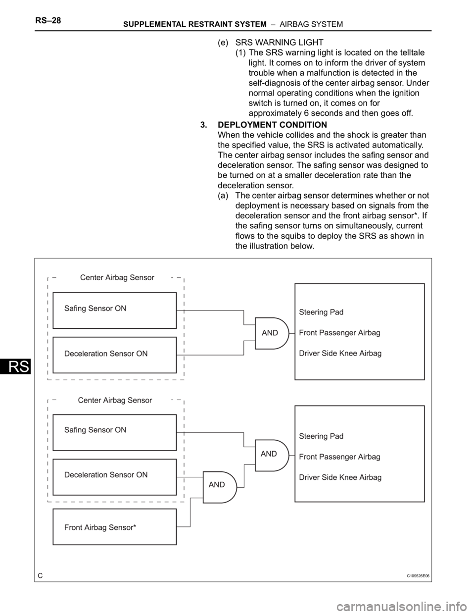
The center airbag sensor includes the safing sensor and
deceleration sensor. The safing sensor was designed to
be turned on at a smaller deceleration rate than the
deceleration sensor.
(a) The center airbag sensor determines whether or not
deployment is necessary based on signals from the
deceleration sensor and the front airbag sensor*. If
the safing sensor turns on simultaneously, current
flows to the squibs to deploy the SRS as shown in
the illustration below.
C109526E06
Page 1685 of 2000
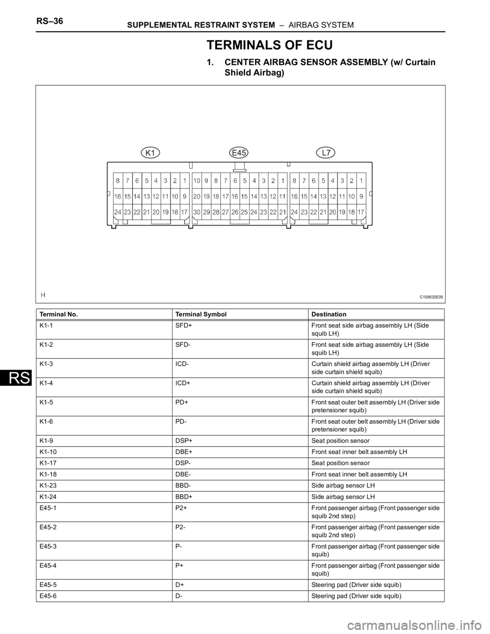
RS–36SUPPLEMENTAL RESTRAINT SYSTEM – AIRBAG SYSTEM
RS
TERMINALS OF ECU
1. CENTER AIRBAG SENSOR ASSEMBLY (w/ Curtain
Shield Airbag)
Terminal No. Terminal Symbol Destination
K1-1 SFD+ Front seat side airbag assembly LH (Side
squib LH)
K1-2 SFD- Front seat side airbag assembly LH (Side
squib LH)
K1-3 ICD- Curtain shield airbag assembly LH (Driver
side curtain shield squib)
K1-4 ICD+ Curtain shield airbag assembly LH (Driver
side curtain shield squib)
K1-5 PD+ Front seat outer belt assembly LH (Driver side
pretensioner squib)
K1-6 PD- Front seat outer belt assembly LH (Driver side
pretensioner squib)
K1-9 DSP+ Seat position sensor
K1-10 DBE+ Front seat inner belt assembly LH
K1-17 DSP- Seat position sensor
K1-18 DBE- Front seat inner belt assembly LH
K1-23 BBD- Side airbag sensor LH
K1-24 BBD+ Side airbag sensor LH
E45-1 P2+ Front passenger airbag (Front passenger side
squib 2nd step)
E45-2 P2- Front passenger airbag (Front passenger side
squib 2nd step)
E45-3 P- Front passenger airbag (Front passenger side
squib)
E45-4 P+ Front passenger airbag (Front passenger side
squib)
E45-5 D+ Steering pad (Driver side squib)
E45-6 D- Steering pad (Driver side squib)
C109532E05