radiator TOYOTA RAV4 2006 Service User Guide
[x] Cancel search | Manufacturer: TOYOTA, Model Year: 2006, Model line: RAV4, Model: TOYOTA RAV4 2006Pages: 2000, PDF Size: 45.84 MB
Page 299 of 2000
PREPARATION – 2GR-FE COOLINGPP–23
PP
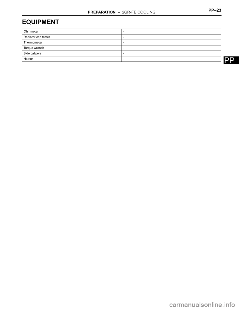
EQUIPMENT
Ohmmeter -
Radiator cap tester -
Thermometer -
Torque wrench -
Side calipers -
Heater -
Page 379 of 2000
SS–12SERVICE SPECIFICATIONS – 2AZ-FE ENGINE MECHANICAL
SS
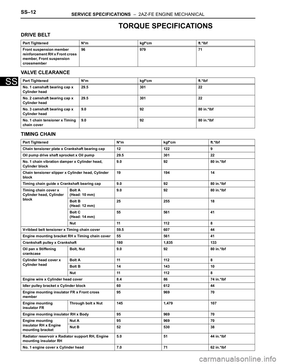
TORQUE SPECIFICATIONS
DRIVE BELT
VALVE CLEARANCE
TIMING CHAIN
Part Tightened N*m kgf*cm ft.*lbf
Front suspension member
reinforcement RH x Front cross
member, Front suspension
crossmember96 979 71
Part Tightened N*m kgf*cm ft.*lbf
No. 1 camshaft bearing cap x
Cylinder head29.5 301 22
No. 2 camshaft bearing cap x
Cylinder head29.5 301 22
No. 3 camshaft bearing cap x
Cylinder head9.0 92 80 in.*lbf
No. 1 chain tensioner x Timing
chain cover9.0 92 80 in.*lbf
Part Tightened N*m kgf*cm ft.*lbf
Chain tensioner plate x Crankshaft bearing cap 12 122 9
Oil pump drive shaft sprocket x Oil pump 29.5 301 22
No. 1 chain vibration damper x Cylinder head,
Cylinder block9.0 92 80 in.*lbf
Chain tensioner slipper x Cylinder head, Cylinder
block19 194 14
Timing chain guide x Crankshaft bearing cap 9.0 92 80 in.*lbf
Timing chain cover x
Cylinder head, Cylinder
blockBolt A
(Head: 10 mm)9.0 92 80 in.*lbf
Bolt B
(Head: 12 mm)25 255 18
Bolt C
(Head: 14 mm)55 561 41
Nut 11 112 8
V-ribbed belt tensioner x Timing chain cover 59.5 607 44
Engine mounting bracket RH x Timing chain cover 55 561 41
Crankshaft pulley x Crankshaft 180 1,835 133
Oil pan x Stiffening
crankcaseBolt, Nut 9.0 92 80 in.*lbf
Cylinder head cover x
Cylinder headBolt A 11 112 8
Bolt B 14 143 10
Nut 11 112 8
Engine wire x Cylinder head cover 8.4 86 74 in.*lbf
Idler pulley bracket x Cylinder block 60 612 44
Engine mounting insulator FR x Front cross
member95 969 70
Engine mounting
insulator FRThrough bolt x Nut 145 1,479 107
Engine mounting insulator RH x Body 95 969 70
Engine mounting
insulator RH x Engine
mounting bracketNut A 95 969 70
Nut B 52 530 38
Radiator reservoir x Radiator support RH, Engine
mounting insulator RH5.0 51 44 in.*lbf
No. 1 engine cover x Cylinder head 7.0 71 62 in.*lbf
Page 380 of 2000
SERVICE SPECIFICATIONS – 2AZ-FE ENGINE MECHANICALSS–13
SS
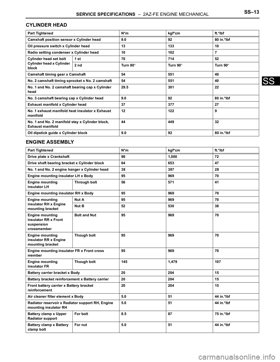
CYLINDER HEAD
ENGINE ASSEMBLY
Part Tightened N*m kgf*cm ft.*lbf
Camshaft position sensor x Cylinder head 9.0 92 80 in.*lbf
Oil pressure switch x Cylinder head 13 133 10
Radio setting condenser x Cylinder head 10 102 7
Cylinder head set bolt
Cylinder head x Cylinder
block1 st 70 714 52
2 nd Turn 90
Tu r n 9 0Tu r n 9 0
Camshaft timing gear x Camshaft 54 551 40
No. 2 camshaft timing sprocket x No. 2 camshaft 54 551 40
No. 1 and No. 2 camshaft bearing cap x Cylinder
head29.5 301 22
No. 3 camshaft bearing cap x Cylinder head 9.0 92 80 in.*lbf
Exhaust manifold x Cylinder head 37 377 27
No. 1 exhaust manifold heat insulator x Exhaust
manifold12 122 9
No. 1 and No. 2 manifold stay x Cylinder block,
Exhaust manifold44 449 32
Oil dipstick guide x Cylinder block 9.0 92 80 in.*lbf
Part Tightened N*m kgf*cm ft.*lbf
Drive plate x Crankshaft 98 1,000 72
Drive shaft bearing bracket x Cylinder block 64 653 47
No. 1 and No. 2 engine hanger x Cylinder head 38 387 28
Engine mounting insulator LH x Body 95 969 70
Engine mounting
insulator LHThrough bolt 56 571 41
Engine mounting insulator RH x Body 95 969 70
Engine mounting
insulator RH x Engine
mounting bracketNut A 95 969 70
Nut B 52 530 38
Engine mounting
insulator RR x Front
suspension
crossmemberBolt and Nut 95 969 70
Engine mounting
insulator RR x Engine
mounting bracketThough bolt 95 969 70
Engine mounting insulator FR x Front cross
member95 969 70
Engine mounting
insulator FRThough bolt 145 1,479 107
Battery carrier bracket x Body 20 204 15
Battery bracket reinforcement x Battery carrier 20 204 15
Front battery carrier x Battery bracket
reinforcement20 204 15
Air cleaner filter element x Body 5.0 51 44 in.*lbf
Radiator reservoir x Radiator support RH, Engine
mounting insulator RH5.0 51 44 in.*lbf
Battery clamp x Upper
Radiator supportFor bolt 8.5 87 75 in.*lbf
Battery clamp x Battery
clamp boltFor nut 5.0 51 44 in.*lbf
Page 383 of 2000
SERVICE SPECIFICATIONS – 2GR-FE ENGINE MECHANICALSS–21
SS
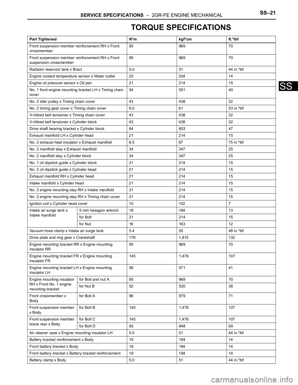
TORQUE SPECIFICATIONS
Part Tightened N*m kgf*cm ft.*lbf
Front suspension member reinforcement RH x Front
crossmember95 969 70
Front suspension member reinforcement RH x Front
suspension crossmember95 969 70
Radiator reservoir tank x Bract 5.0 51 44 in.*lbf
Engine coolant temperature sensor x Water outlet 20 204 14
Engine oil pressure sensor x Oil pan 21 214 15
No. 1 front engine mounting bracket LH x Timing chain
cover54 551 40
No. 2 idler pulley x Timing chain cover 43 438 32
No. 2 timing gear cover x Timing chain cover 6.0 61 53 in.*lbf
V-ribbed belt tensioner x Timing chain cover 43 438 32
V-ribbed belt tensioner x Cylinder block 43 438 32
Drive shaft bearing bracket x Cylinder block 64 653 47
Exhaust manifold LH x Cylinder head 21 214 15
No. 2 exhaust heat insulator x Exhaust manifold 8.5 87 75 in.*lbf
No. 2 manifold stay x Exhaust manifold 34 347 25
No. 2 manifold stay x Cylinder block 34 347 25
No. 1 oil dipstick guide x Cylinder block 21 214 15
No. 2 oil dipstick guide x Cylinder head 21 214 15
Exhaust manifold RH x Cylinder head 21 214 15
Intake manifold x Cylinder head 21 214 15
No. 2 engine mounting stay RH x Intake manifold 21 214 15
No. 2 engine mounting stay RH x Timing chain cover 21 214 15
Ignition coil x Cylinder head cover 10 102 7
Intake air surge tank x
Intake manifold5 mm hexagon wrench 18 184 13
for Bolt 21 214 15
for Nut 16 163 12
Vacuum hose clamp x Intake air surge tank 5.4 55 48 in.*lbf
Drive plate and ring gear x Crankshaft 178 1,815 132
Engine mounting bracket RR x Engine mounting
insulator RR95 969 70
Engine mounting bracket FR x Engine mounting
insulator FR145 1,479 107
Engine mounting bracket LH x Engine mounting
insulator LH56 571 41
Engine mounting insulator
RH x Front No. 1 engine
mounting bracketfor Bolt and nut A 95 969 70
for Nut B 52 530 38
Front crossmember x
Bodyfor Bolt A 96 979 71
Front suspension member
x Bodyfor Bolt B 145 1,478 107
Front suspension member
brace rear x Bodyfor Bolt C 145 1,478 107
for Bolt D 93 948 69
Air cleaner case x Engine mounting insulator LH 5.0 51 44 in.*lbf
Battery bracket reinforcement x Body 19 194 14
Front battery bracket x Body 19 194 14
Front battery bracket x Battery bracket reinforcement 19 194 14
Battery clamp x Body 5.0 51 44 in.*lbf
Page 429 of 2000
AIR CONDITIONING – AIR OUTLET CONTROL SERVO MOTOR (for Automatic Air Condi-
tioning System)AC–213
AC
INSTALLATION
1. INSTALL AIR OUTLET CONTROL SERVO MOTOR
(See page AC-196)
2. INSTALL AIR CONDITIONING UNIT
(a) Install the air conditioning radiator (see page AC-
197).
Page 510 of 2000
ET–4EXTERIOR – FRONT BUMPER
ET
REMOVAL
1. DISCONNECT CABLE FROM NEGATIVE BATTERY
TERMINAL
CAUTION:
Wait at least 90 seconds after disconnecting the
cable from the negative (-) battery terminal to
prevent airbag and seat belt pretensioner activation.
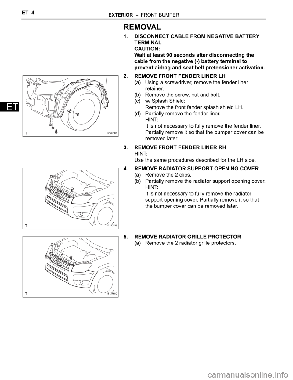
2. REMOVE FRONT FENDER LINER LH
(a) Using a screwdriver, remove the fender liner
retainer.
(b) Remove the screw, nut and bolt.
(c) w/ Splash Shield:
Remove the front fender splash shield LH.
(d) Partially remove the fender liner.
HINT:
It is not necessary to fully remove the fender liner.
Partially remove it so that the bumper cover can be
removed later.
3. REMOVE FRONT FENDER LINER RH
HINT:
Use the same procedures described for the LH side.
4. REMOVE RADIATOR SUPPORT OPENING COVER
(a) Remove the 2 clips.
(b) Partially remove the radiator support opening cover.
HINT:
It is not necessary to fully remove the radiator
support opening cover. Partially remove it so that
the bumper cover can be removed later.
5. REMOVE RADIATOR GRILLE PROTECTOR
(a) Remove the 2 radiator grille protectors.
B133187
B130259
B137680
Page 512 of 2000
ET–6EXTERIOR – FRONT BUMPER
ET
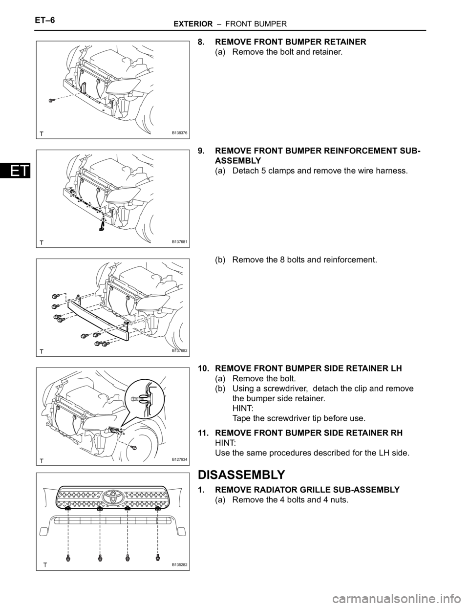
8. REMOVE FRONT BUMPER RETAINER
(a) Remove the bolt and retainer.
9. REMOVE FRONT BUMPER REINFORCEMENT SUB-
ASSEMBLY
(a) Detach 5 clamps and remove the wire harness.
(b) Remove the 8 bolts and reinforcement.
10. REMOVE FRONT BUMPER SIDE RETAINER LH
(a) Remove the bolt.
(b) Using a screwdriver, detach the clip and remove
the bumper side retainer.
HINT:
Tape the screwdriver tip before use.
11. REMOVE FRONT BUMPER SIDE RETAINER RH
HINT:
Use the same procedures described for the LH side.
DISASSEMBLY
1. REMOVE RADIATOR GRILLE SUB-ASSEMBLY
(a) Remove the 4 bolts and 4 nuts.
B139376
B137681
B137682
B127934
B135282
Page 513 of 2000
EXTERIOR – FRONT BUMPERET–7
ET
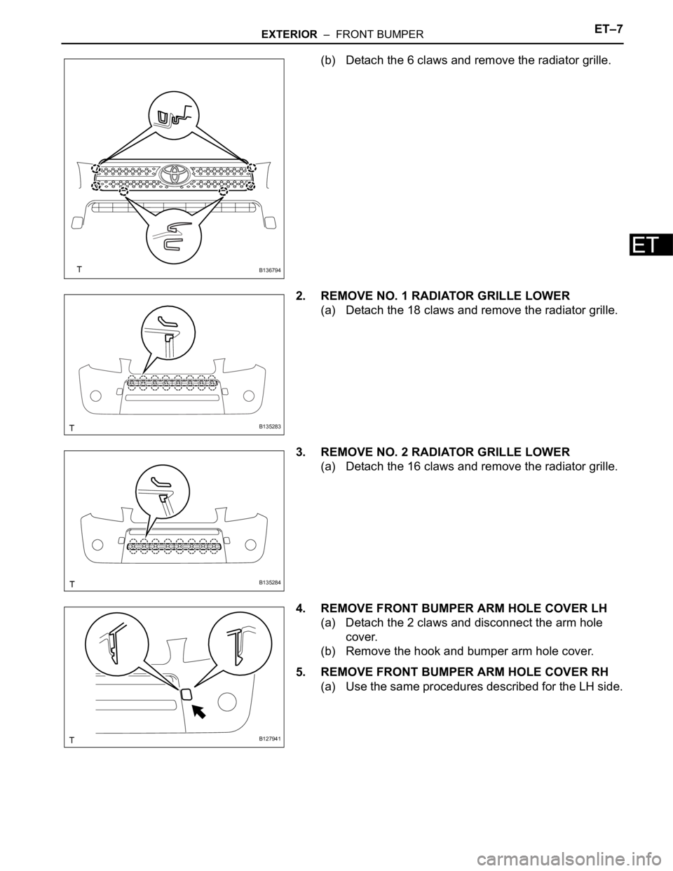
(b) Detach the 6 claws and remove the radiator grille.
2. REMOVE NO. 1 RADIATOR GRILLE LOWER
(a) Detach the 18 claws and remove the radiator grille.
3. REMOVE NO. 2 RADIATOR GRILLE LOWER
(a) Detach the 16 claws and remove the radiator grille.
4. REMOVE FRONT BUMPER ARM HOLE COVER LH
(a) Detach the 2 claws and disconnect the arm hole
cover.
(b) Remove the hook and bumper arm hole cover.
5. REMOVE FRONT BUMPER ARM HOLE COVER RH
(a) Use the same procedures described for the LH side.
B136794
B135283
B135284
B127941
Page 515 of 2000
EXTERIOR – FRONT BUMPERET–9
ET
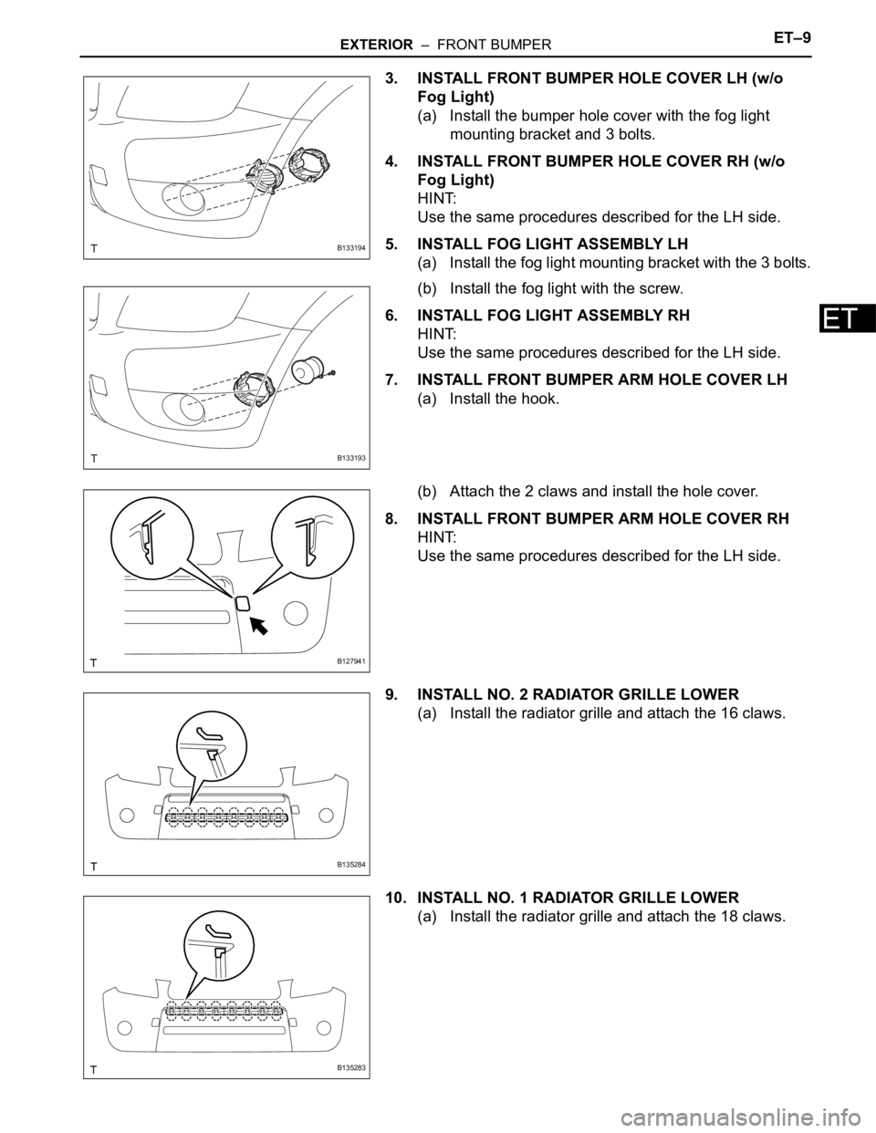
3. INSTALL FRONT BUMPER HOLE COVER LH (w/o
Fog Light)
(a) Install the bumper hole cover with the fog light
mounting bracket and 3 bolts.
4. INSTALL FRONT BUMPER HOLE COVER RH (w/o
Fog Light)
HINT:
Use the same procedures described for the LH side.
5. INSTALL FOG LIGHT ASSEMBLY LH
(a) Install the fog light mounting bracket with the 3 bolts.
(b) Install the fog light with the screw.
6. INSTALL FOG LIGHT ASSEMBLY RH
HINT:
Use the same procedures described for the LH side.
7. INSTALL FRONT BUMPER ARM HOLE COVER LH
(a) Install the hook.
(b) Attach the 2 claws and install the hole cover.
8. INSTALL FRONT BUMPER ARM HOLE COVER RH
HINT:
Use the same procedures described for the LH side.
9. INSTALL NO. 2 RADIATOR GRILLE LOWER
(a) Install the radiator grille and attach the 16 claws.
10. INSTALL NO. 1 RADIATOR GRILLE LOWER
(a) Install the radiator grille and attach the 18 claws.
B133194
B133193
B127941
B135284
B135283
Page 516 of 2000
ET–10EXTERIOR – FRONT BUMPER
ET
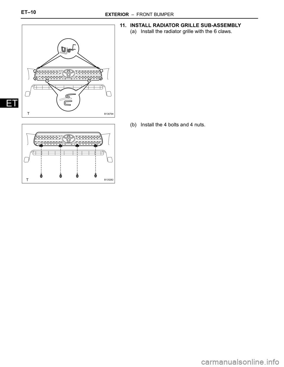
11. INSTALL RADIATOR GRILLE SUB-ASSEMBLY
(a) Install the radiator grille with the 6 claws.
(b) Install the 4 bolts and 4 nuts.
B136794
B135282