radiator TOYOTA RAV4 2006 Service Workshop Manual
[x] Cancel search | Manufacturer: TOYOTA, Model Year: 2006, Model line: RAV4, Model: TOYOTA RAV4 2006Pages: 2000, PDF Size: 45.84 MB
Page 867 of 2000

CO–382GR-FE COOLING – RADIATOR
CO
(b) Detach the 3 harness clamps from the fan shroud
and upper radiator support.
16. DISCONNECT HORN CONNECTOR
(a) Disconnect the 2 horn connectors.
17. REMOVE UPPER RADIATOR SUPPORT BRACKET
(a) Remove the 2 bolts and 2 upper radiator support
brackets.
18. REMOVE NO. 2 FAN SHROUD
(a) Remove the 2 bolts.
(b) Detach the 2 claws and No. 2 shroud.
A136804
A112185E02
A112186E01
Page 868 of 2000

2GR-FE COOLING – RADIATORCO–39
CO
19. REMOVE UPPER RADIATOR SUPPORT SUB-
ASSEMBLY
(a) Remove the 4 bolts and upper radiator support with
hood lock.
20. DISCONNECT OIL COOLER INLET HOSE
21. DISCONNECT OIL COOLER OUTLET HOSE
22. DISCONNECT NO. 1 RADIATOR HOSE
23. DISCONNECT NO. 2 RADIATOR HOSE
24. DISCONNECT NO. 2 WATER BY-PASS HOSE
(a) Disconnect the by-pass hose from the radiator
reservoir and radiator.
25. REMOVE RADIATOR ASSEMBLY
(a) Detach the cooler condenser from the radiator.
HINT:
After detaching the condenser, make sure that all 4
fan shroud cushions are present.
(b) Remove the radiator with the 2 radiator support
lower cushions.
HINT:
After detaching the radiator, make sure that all 2
radiator support lowers are present.
A112338
A112334E01
Page 869 of 2000

CO–402GR-FE COOLING – RADIATOR
CO
26. REMOVE FAN SHROUD WITH COOLING FAN
(a) Remove the 2 bolts and fan shroud with cooling fan
from the radiator.
INSTALLATION
1. INSTALL FAN SHROUD WITH COOLING FAN
(a) Install the fan shroud with cooling fan to the radiator
with the 2 bolts.
Torque: 10.5 N*m (107 kgf*cm, 8 ft.*lbf)
2. INSTALL RADIATOR ASSEMBLY
(a) Install the 4 fan shroud cushions to the cooler
condenser.
(b) Set the cooler condenser into the fan shroud.
(c) Install the 2 radiator support lower cushions to the
fan shroud.
(d) Install the radiator with cooler condenser and fan
shroud to the radiator support lowers.
3. INSTALL UPPER RADIATOR SUPPORT SUB-
ASSEMBLY
(a) Install the upper radiator support with the 4 bolts.
Torque: 29 N*m (296 kgf*cm, 21 ft.*lbf)
4. INSTALL NO. 2 FAN SHROUD
(a) Attach the 2 claws to install the No. 2 fan shroud,
and install the 2 bolts.
Torque: 10.5 N*m (107 kgf*cm, 8 ft.*lbf)
A114328
A114328
A136813
A112338
A112186E01
Page 870 of 2000

2GR-FE COOLING – RADIATORCO–41
CO
5. INSTALL UPPER RADIATOR SUPPORT BRACKET
(a) Install the brackets with the 2 bolts.
Torque: 19 N*m (194 kgf*cm, 14 ft.*lbf)
6. CONNECT HORN CONNECTOR
(a) Connect the 2 horn connectors.
7. CONNECT NO. 2 WATER BY-PASS HOSE
(a) Connect the by-pass hose to the radiator and
radiator reservoir.
HINT:
The direction of the hose clamp is indicated in the
illustration.
8. CONNECT NO. 2 RADIATOR HOSE
HINT:
The direction of the hose clamp is indicated in the
illustration.
9. CONNECT NO. 1 RADIATOR HOSE
HINT:
The direction of the hose clamp is indicated in the
illustration.
10. CONNECT OIL COOLER OUTLET HOSE
11. CONNECT OIL COOLER INLET HOSE
12. CONNECT COOLING FAN ECU HARNESS (w/ Trailer
Towing System)
(a) Attach the harness with the 3 clamps.
A112185E02
A112335E01
Page 871 of 2000
CO–422GR-FE COOLING – RADIATOR
CO
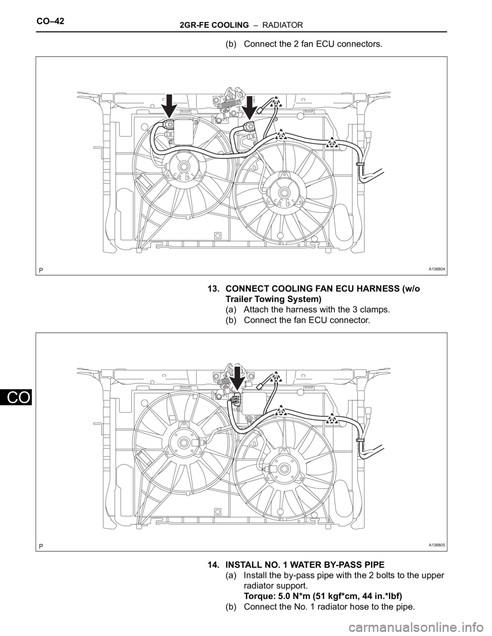
(b) Connect the 2 fan ECU connectors.
13. CONNECT COOLING FAN ECU HARNESS (w/o
Trailer Towing System)
(a) Attach the harness with the 3 clamps.
(b) Connect the fan ECU connector.
14. INSTALL NO. 1 WATER BY-PASS PIPE
(a) Install the by-pass pipe with the 2 bolts to the upper
radiator support.
Torque: 5.0 N*m (51 kgf*cm, 44 in.*lbf)
(b) Connect the No. 1 radiator hose to the pipe.
A136804
A136805
Page 872 of 2000
2GR-FE COOLING – RADIATORCO–43
CO
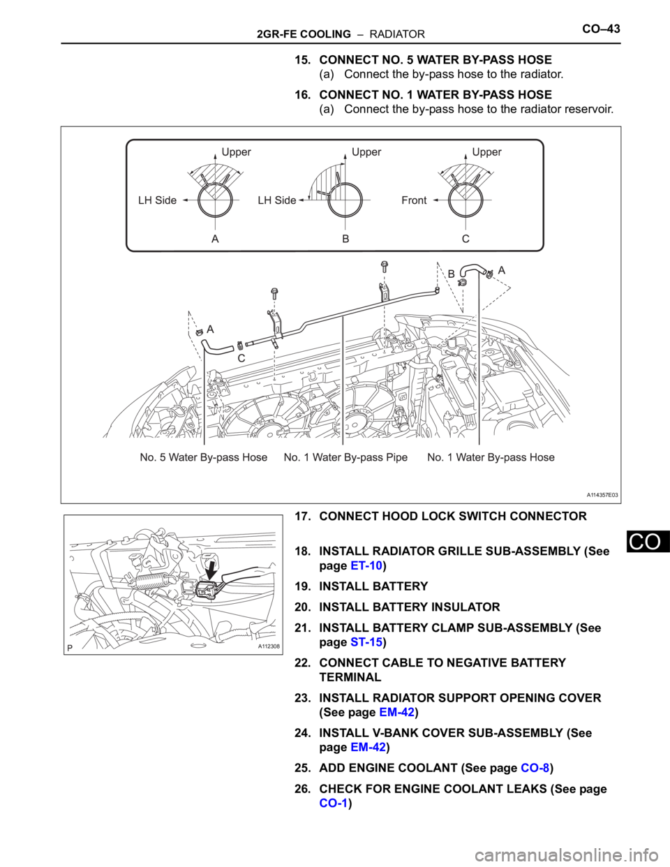
15. CONNECT NO. 5 WATER BY-PASS HOSE
(a) Connect the by-pass hose to the radiator.
16. CONNECT NO. 1 WATER BY-PASS HOSE
(a) Connect the by-pass hose to the radiator reservoir.
17. CONNECT HOOD LOCK SWITCH CONNECTOR
18. INSTALL RADIATOR GRILLE SUB-ASSEMBLY (See
page ET-10)
19. INSTALL BATTERY
20. INSTALL BATTERY INSULATOR
21. INSTALL BATTERY CLAMP SUB-ASSEMBLY (See
page ST-15)
22. CONNECT CABLE TO NEGATIVE BATTERY
TERMINAL
23. INSTALL RADIATOR SUPPORT OPENING COVER
(See page EM-42)
24. INSTALL V-BANK COVER SUB-ASSEMBLY (See
page EM-42)
25. ADD ENGINE COOLANT (See page CO-8)
26. CHECK FOR ENGINE COOLANT LEAKS (See page
CO-1)
A114357E03
A112308
Page 873 of 2000
CO–442GR-FE COOLING – RADIATOR
CO
27. INSTALL NO. 1 ENGINE UNDER COVER (See page
EM-41)
Page 931 of 2000
CH–122GR-FE CHARGING – GENERATOR
CH
REMOVAL
1. REMOVE RADIATOR ASSEMBLY
(a) Remove the radiator (see page CO-36).
2. REMOVE FRONT WHEEL RH
3. REMOVE ENGINE UNDER COVER REAR RH (See
page EM-21)
4. REMOVE FRONT SUSPENSION MEMBER
REINFORCEMENT RH (See page EM-7)
5. REMOVE RADIATOR RESERVOIR TANK (See page
CO-19)
6. REMOVE FAN AND GENERATOR V BELT (See page
EM-8)
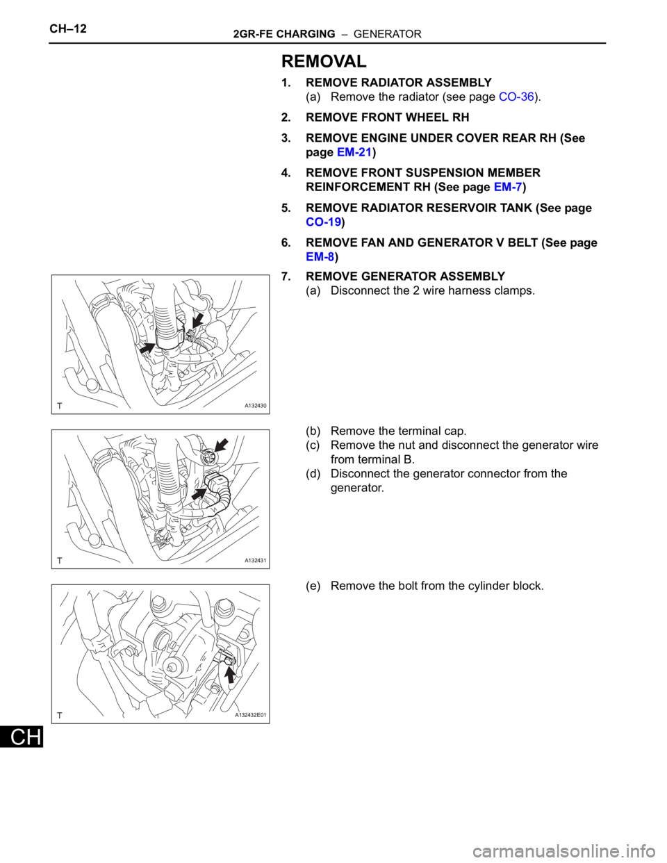
7. REMOVE GENERATOR ASSEMBLY
(a) Disconnect the 2 wire harness clamps.
(b) Remove the terminal cap.
(c) Remove the nut and disconnect the generator wire
from terminal B.
(d) Disconnect the generator connector from the
generator.
(e) Remove the bolt from the cylinder block.
A132430
A132431
A132432E01
Page 939 of 2000
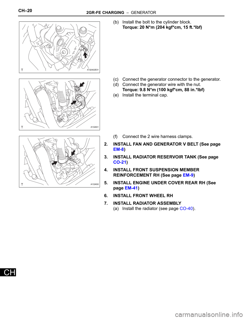
CH–202GR-FE CHARGING – GENERATOR
CH
(b) Install the bolt to the cylinder block.
Torque: 20 N*m (204 kgf*cm, 15 ft.*lbf)
(c) Connect the generator connector to the generator.
(d) Connect the generator wire with the nut.
Torque: 9.8 N*m (100 kgf*cm, 88 in.*lbf)
(e) Install the terminal cap.
(f) Connect the 2 wire harness clamps.
2. INSTALL FAN AND GENERATOR V BELT (See page
EM-8)
3. INSTALL RADIATOR RESERVOIR TANK (See page
CO-21)
4. INSTALL FRONT SUSPENSION MEMBER
REINFORCEMENT RH (See page EM-9)
5. INSTALL ENGINE UNDER COVER REAR RH (See
page EM-41)
6. INSTALL FRONT WHEEL RH
7. INSTALL RADIATOR ASSEMBLY
(a) Install the radiator (see page CO-40).
A132432E01
A132431
A132430
Page 1651 of 2000
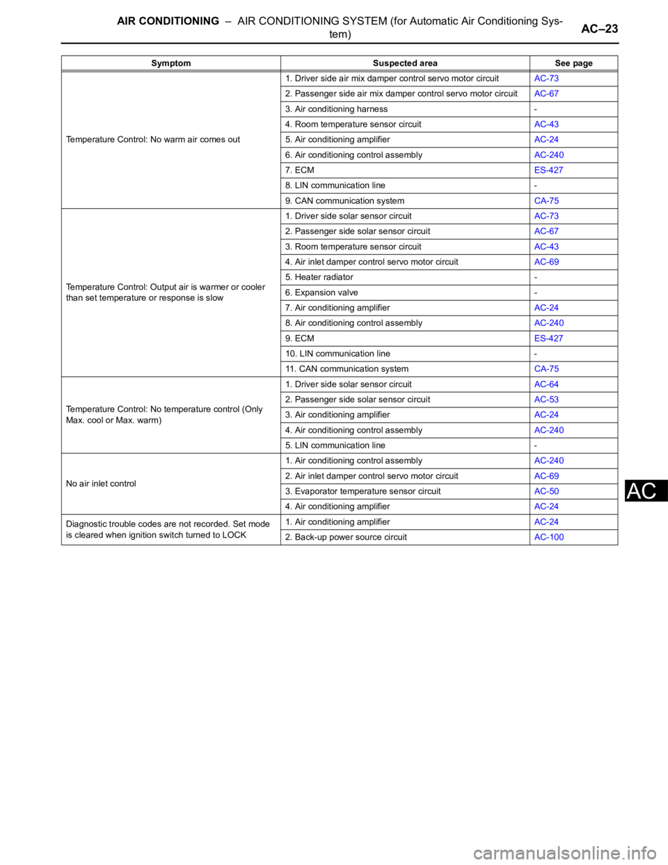
AIR CONDITIONING – AIR CONDITIONING SYSTEM (for Automatic Air Conditioning Sys-
tem)AC–23
AC
Temperature Control: No warm air comes out1. Driver side air mix damper control servo motor circuitAC-73
2. Passenger side air mix damper control servo motor circuitAC-67
3. Air conditioning harness -
4. Room temperature sensor circuitAC-43
5. Air conditioning amplifierAC-24
6. Air conditioning control assemblyAC-240
7. ECMES-427
8. LIN communication line -
9. CAN communication systemCA-75
Temperature Control: Output air is warmer or cooler
than set temperature or response is slow1. Driver side solar sensor circuitAC-73
2. Passenger side solar sensor circuitAC-67
3. Room temperature sensor circuitAC-43
4. Air inlet damper control servo motor circuitAC-69
5. Heater radiator -
6. Expansion valve -
7. Air conditioning amplifierAC-24
8. Air conditioning control assemblyAC-240
9. ECMES-427
10. LIN communication line -
11. CAN communication systemCA-75
Temperature Control: No temperature control (Only
Max. cool or Max. warm)1. Driver side solar sensor circuitAC-64
2. Passenger side solar sensor circuitAC-53
3. Air conditioning amplifierAC-24
4. Air conditioning control assemblyAC-240
5. LIN communication line -
No air inlet control1. Air conditioning control assemblyAC-240
2. Air inlet damper control servo motor circuitAC-69
3. Evaporator temperature sensor circuitAC-50
4. Air conditioning amplifierAC-24
Diagnostic trouble codes are not recorded. Set mode
is cleared when ignition switch turned to LOCK1. Air conditioning amplifierAC-24
2. Back-up power source circuitAC-100 Symptom Suspected area See page