sensor TOYOTA RAV4 2006 Service Repair Manual
[x] Cancel search | Manufacturer: TOYOTA, Model Year: 2006, Model line: RAV4, Model: TOYOTA RAV4 2006Pages: 2000, PDF Size: 45.84 MB
Page 1352 of 2000

TF–24GF1A TRANSFER – ACTIVE TORQUE CONTROL 4WD SYSTEM
TF
DESCRIPTION
If a malfunction in the power source circuit occurs, or a malfunction in communication with the skid control
ECU or in a speed sensor occurs, the 4WD control ECU will prohibit operations by the fail-safe function.
WIRING DIAGRAM
INSPECTION PROCEDURE
HINT:
Check the condition of each related circuit connector before troubleshooting (see page IN-37).
DTC C1241/94 Low Power Supply Voltage
DTC No. DTC Detection Condition Trouble Area
C1241/94 When one of following conditions is met:
1. When following continues for 10 seconds
or more:
- At a vehicle speed of 3 km/h (2 mph) or
more, voltage of IG1 terminal is 9.5 V or
less.
2. When both of following continue for 60
seconds or more:
- With the voltage of IG1 terminal 9.5 V or
less, communication with the skid control
ECU cannot be performed.
- A malfunction in communication with
skid control ECU.
3. When following continue for 3 seconds or
more:
- With the voltage of IG1 terminal 9.5 V or
more, communication with the skid control
ECU cannot be performed.•Battery
• Generator
•ECU-IG1
• Wire harness (IG1 circuit, GND circuit)
• 4WD control ECU
C128626E02
Page 1353 of 2000
GF1A TRANSFER – ACTIVE TORQUE CONTROL 4WD SYSTEMTF–25
TF
(a) Clear the DTC (see page TF-16).
(b) Turn the ignition switch ON and check that no CAN
communication system DTC is output.
(c) Start the engine.
(d) Drive the vehicle, accelerate to a speed of 3 km/h (2
mph) or more, and check that no speed sensor DTC
(brake control system DTC) is output (see page BC-57).
Result
B
C
A
(a) Remove the ECU-IG1 fuse from the instrument junction
block
(b) Measure the resistance of the fuse.
Standard resistance:
Below 1
HINT:
Check for short circuits in all harnesses and connector
connected to the ECU-IG1 fuse (see page IN-5).
NG
OK
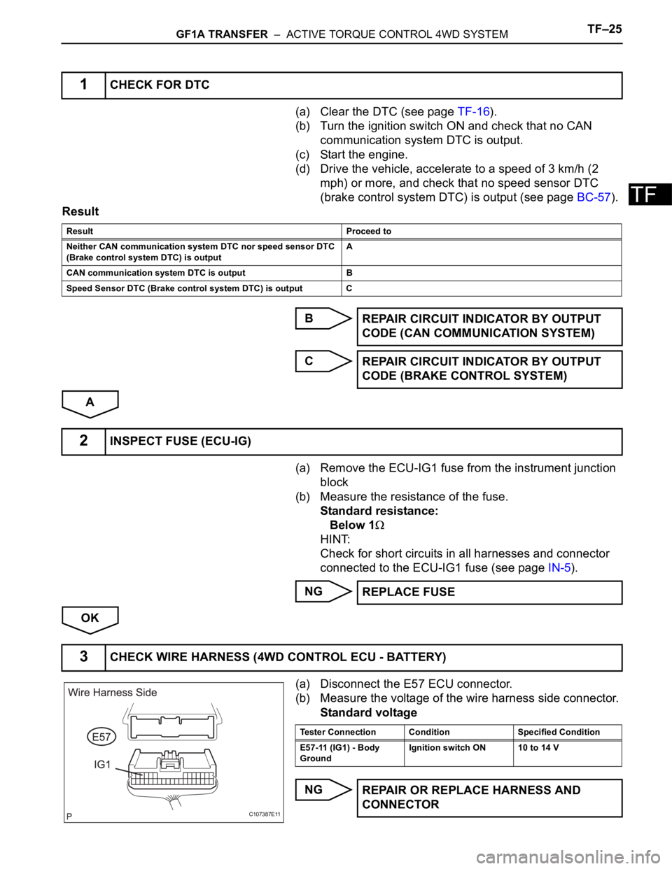
(a) Disconnect the E57 ECU connector.
(b) Measure the voltage of the wire harness side connector.
Standard voltage
NG
1CHECK FOR DTC
Result Proceed to
Neither CAN communication system DTC nor speed sensor DTC
(Brake control system DTC) is outputA
CAN communication system DTC is output B
Speed Sensor DTC (Brake control system DTC) is output C
REPAIR CIRCUIT INDICATOR BY OUTPUT
CODE (CAN COMMUNICATION SYSTEM)
REPAIR CIRCUIT INDICATOR BY OUTPUT
CODE (BRAKE CONTROL SYSTEM)
2INSPECT FUSE (ECU-IG)
REPLACE FUSE
3CHECK WIRE HARNESS (4WD CONTROL ECU - BATTERY)
C107387E11
Tester Connection Condition Specified Condition
E57-11 (IG1) - Body
GroundIgnition switch ON 10 to 14 V
REPAIR OR REPLACE HARNESS AND
CONNECTOR
Page 1354 of 2000
TF–26GF1A TRANSFER – ACTIVE TORQUE CONTROL 4WD SYSTEM
TF
OK
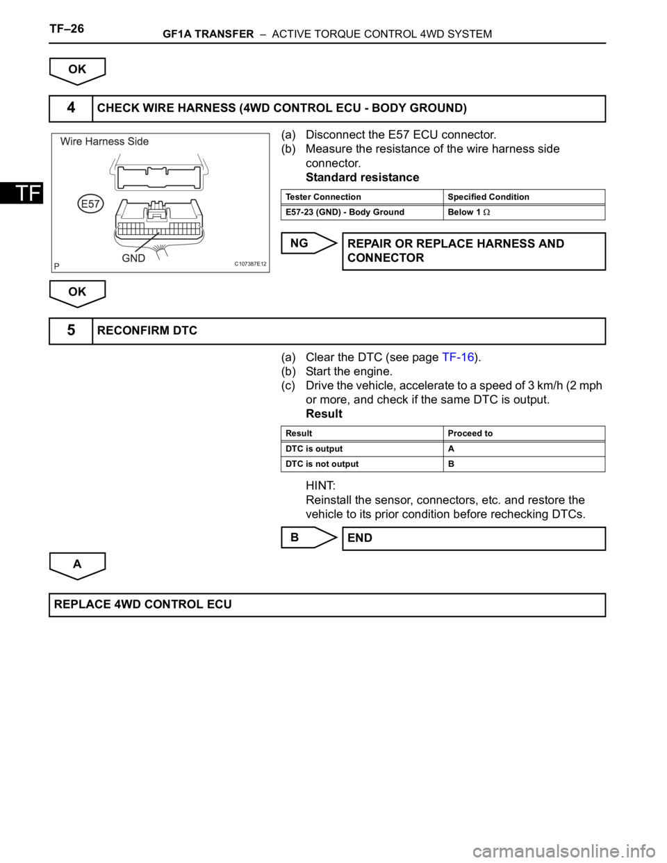
(a) Disconnect the E57 ECU connector.
(b) Measure the resistance of the wire harness side
connector.
Standard resistance
NG
OK
(a) Clear the DTC (see page TF-16).
(b) Start the engine.
(c) Drive the vehicle, accelerate to a speed of 3 km/h (2 mph
or more, and check if the same DTC is output.
Result
HINT:
Reinstall the sensor, connectors, etc. and restore the
vehicle to its prior condition before rechecking DTCs.
B
A
4CHECK WIRE HARNESS (4WD CONTROL ECU - BODY GROUND)
C107387E12
Tester Connection Specified Condition
E57-23 (GND) - Body Ground Below 1
REPAIR OR REPLACE HARNESS AND
CONNECTOR
5RECONFIRM DTC
Result Proceed to
DTC is output A
DTC is not output B
END
REPLACE 4WD CONTROL ECU
Page 1355 of 2000
GF1A TRANSFER – ACTIVE TORQUE CONTROL 4WD SYSTEMTF–27
TF
DESCRIPTION
If a malfunction in the engine control ECU circuit occurs, the 4WD control ECU will output this DTC.
INSPECTION PROCEDURE
HINT:
Check the condition of each related circuit connector before troubleshooting (see page IN-37).
(a) Clear the DTC (see page TF-16).
(b) Turn the ignition switch OFF.
(c) Turn the ignition switch ON and check that can
communication system DTC is not output.
Result
B
A
DTC C1280/82 Engine Circuit Malfunction
DTC No. DTC Detection Condition Trouble Area
C1280/82 When the following continues for 5 seconds
or more:
- Communication with engine control ECU is
operating normally, but throttle position
sensor is malfunctioning.• Throttle position sensor
• Throttle position sensor wire harness and
connector
• CAN communication system
1CHECK FOR DTC
Result Proceed to
CAN communication system DTC is
outputA
Engine control DTC is output B
GO TO ENGINE CONTROL SYSTEM
GO TO CAN COMMUNICATION SYSTEM
Page 1356 of 2000
TF–28GF1A TRANSFER – ACTIVE TORQUE CONTROL 4WD SYSTEM
TF
DESCRIPTION
If a malfunction in the speed sensor signal circuit yaw rate sensor circuit occurs, the 4WD control ECU will
output this DTC.
INSPECTION PROCEDURE
HINT:
Check the condition of each related circuit connector before troubleshooting (see page IN-37).
(a) Clear the DTC (see page TF-16).
(b) Turn the ignition switch OFF.
(c) Turn the ignition switch ON again and check that CAN
communication system DTC(s) is not output.
(d) Drive the vehicle, accelerate to a speed of 20 km/h (12
mph) or more, and check if the speed sensor DTC (brake
control system DTC) is output (see page BC-57).
Result
HINT:
When DTCs indicating a CAN communication system
malfunction are output, repair the CAN communication
system before repairing each corresponding sensor.
B
C
A
(a) Replace the 4WD control ECU with a normally
functioning or new one.
(b) Reconfirm DTC.
DTC C1296/96 ABS Malfunction
DTC No. DTC Detection Condition Trouble Area
C1296/96 When either condition below is met:
1. Wheel speed sensor malfunction is
received from skid control ECU
2. Deceleration sensor malfunction us
received from skid control ECU• CAN communication line
• Skid control ECU
• Speed sensor
• 4WD control ECU
• Yaw rate sensor
• Wire harness
1CHECK FOR DTC
Result Proceed to
Neither CAN communication system
DTC nor brake control system DTC is
out putA
CAN communication system DTC is
outputB
Brake control system DTC (speed
sensor DTC) is outputC
REPAIR CIRCUIT INDICATOR BY OUTPUT
CODE (CAN COMMUNICATION SYSTEM)
REPAIR CIRCUIT INDICATOR BY OUTPUT
CODE (BRAKE CONTROL SYSTEM)
2CHECK OPERATION OF 4WD CONTROL ECU
Page 1358 of 2000
TF–30GF1A TRANSFER – ACTIVE TORQUE CONTROL 4WD SYSTEM
TF
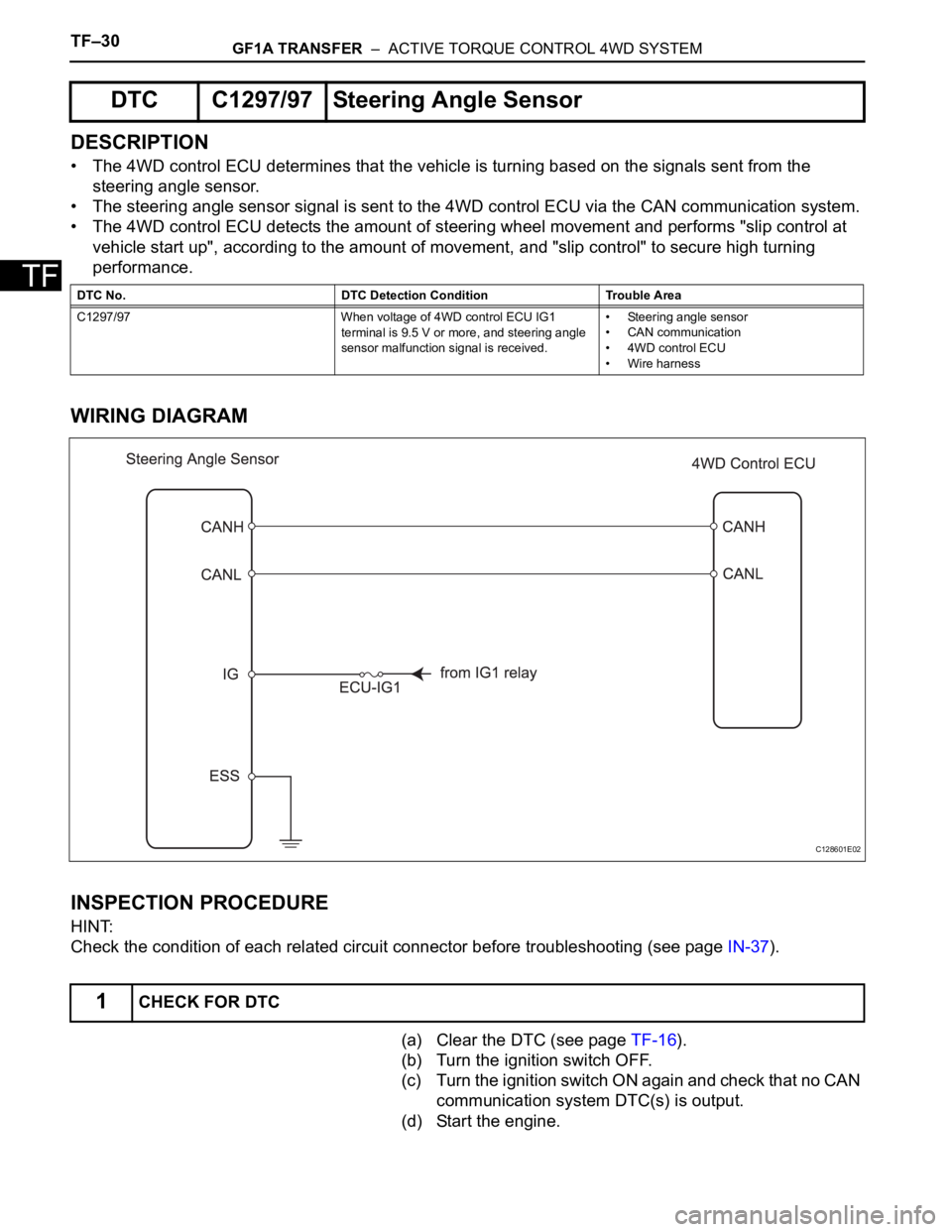
DESCRIPTION
• The 4WD control ECU determines that the vehicle is turning based on the signals sent from the
steering angle sensor.
• The steering angle sensor signal is sent to the 4WD control ECU via the CAN communication system.
• The 4WD control ECU detects the amount of steering wheel movement and performs "slip control at
vehicle start up", according to the amount of movement, and "slip control" to secure high turning
performance.
WIRING DIAGRAM
INSPECTION PROCEDURE
HINT:
Check the condition of each related circuit connector before troubleshooting (see page IN-37).
(a) Clear the DTC (see page TF-16).
(b) Turn the ignition switch OFF.
(c) Turn the ignition switch ON again and check that no CAN
communication system DTC(s) is output.
(d) Start the engine.
DTC C1297/97 Steering Angle Sensor
DTC No. DTC Detection Condition Trouble Area
C1297/97 When voltage of 4WD control ECU IG1
terminal is 9.5 V or more, and steering angle
sensor malfunction signal is received.• Steering angle sensor
• CAN communication
• 4WD control ECU
• Wire harness
1CHECK FOR DTC
C128601E02
Page 1359 of 2000
GF1A TRANSFER – ACTIVE TORQUE CONTROL 4WD SYSTEMTF–31
TF
(e) Drive the vehicle and turn the steering wheel to the right
and left at a speed of 35 km/h (24 mph) and check that
no brake control system (steering angle sensor) DTC
(C1231/31) is output (see page BC-57).
Result
HINT:
When DTCs indicating a CAN communication system
malfunction are output, repair the CAN communication
system before repairing each corresponding sensor.
B
C
A
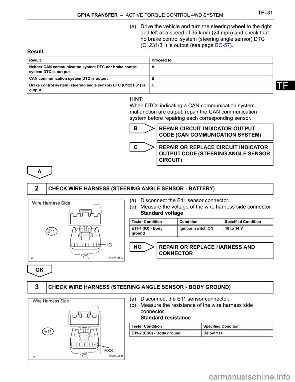
(a) Disconnect the E11 sensor connector.
(b) Measure the voltage of the wire harness side connector.
Standard voltage
NG
OK
(a) Disconnect the E11 sensor connector.
(b) Measure the resistance of the wire harness side
connector.
Standard resistance
Result Proceed to
Neither CAN communication system DTC nor brake control
system DTC is out putA
CAN communication system DTC is output B
Brake control system (steering angle sensor) DTC (C1231/31) is
output C
REPAIR CIRCUIT INDICATOR OUTPUT
CODE (CAN COMMUNICATION SYSTEM)
REPAIR OR REPLACE CIRCUIT INDICATOR
OUTPUT CODE (STEERING ANGLE SENSOR
CIRCUIT)
2CHECK WIRE HARNESS (STEERING ANGLE SENSOR - BATTERY)
C107442E10
Tester Condition Condition Specified Condition
E11-1 (IG) - Body
groundIgnition switch ON 10 to 14 V
REPAIR OR REPLACE HARNESS AND
CONNECTOR
3CHECK WIRE HARNESS (STEERING ANGLE SENSOR - BODY GROUND)
C107442E11
Tester Condition Specified Condition
E11-2 (ESS) - Body ground Below 1
Page 1360 of 2000
TF–32GF1A TRANSFER – ACTIVE TORQUE CONTROL 4WD SYSTEM
TF
Result
B
C
A
Result Proceed to
OK (When troubleshooting according to PROBLEM SYMPTOMS
TABLE)A
OK (When troubleshooting according to DTC chart) B
NG C
PROCEED TO NEXT CIRCUIT INSPECTION
SHOWN IN PROBLEM SYMPTOMS TABLE
REPAIR OR REPLACE HARNESS AND
CONNECTOR
REPLACE STEERING ANGLE SENSOR
Page 1361 of 2000
GF1A TRANSFER – ACTIVE TORQUE CONTROL 4WD SYSTEMTF–33
TF
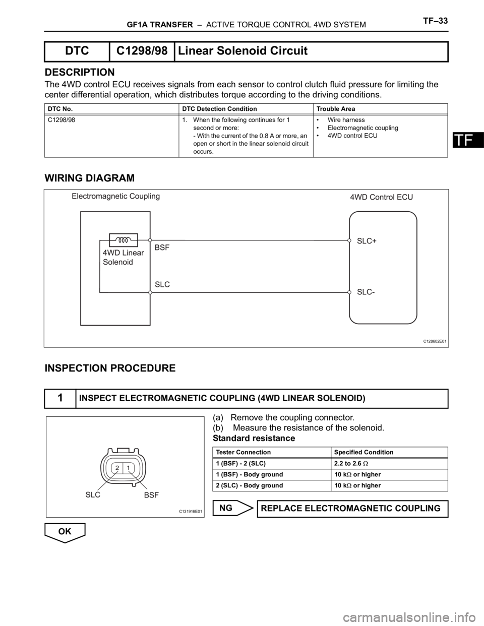
DESCRIPTION
The 4WD control ECU receives signals from each sensor to control clutch fluid pressure for limiting the
center differential operation, which distributes torque according to the driving conditions.
WIRING DIAGRAM
INSPECTION PROCEDURE
(a) Remove the coupling connector.
(b) Measure the resistance of the solenoid.
Standard resistance
NG
OK
DTC C1298/98 Linear Solenoid Circuit
DTC No. DTC Detection Condition Trouble Area
C1298/98 1. When the following continues for 1
second or more:
- With the current of the 0.8 A or more, an
open or short in the linear solenoid circuit
occurs.• Wire harness
• Electromagnetic coupling
• 4WD control ECU
1INSPECT ELECTROMAGNETIC COUPLING (4WD LINEAR SOLENOID)
C128602E01
C131916E01
Tester Connection Specified Condition
1 (BSF) - 2 (SLC) 2.2 to 2.6
1 (BSF) - Body ground 10 k or higher
2 (SLC) - Body ground 10 k
or higher
REPLACE ELECTROMAGNETIC COUPLING
Page 1363 of 2000
DRIVE SHAFT – FRONT DRIVE SHAFT ASSEMBLY (for 2WD)DS–7
DS
REMOVAL
(2005/11-2006/01)
1. REMOVE FRONT WHEEL
2. DRAIN AUTOMATIC TRANSAXLE FLUID
(a) Drain the automatic transaxle fluid for U140F (see
page AX-147).
(b) Drain the automatic transaxle fluid for U241E (see
page AX-146).
3. REMOVE FRONT AXLE HUB NUT (See page AH-6)
4. DISCONNECT FRONT SPEED SENSOR LH
(a) Disconnect the speed sensor (see page BC-191).
5. DISCONNECT FRONT SPEED SENSOR RH
HINT:
Use the same procedures described for the LH side.
6. DISCONNECT FRONT DISC BRAKE CYLINDER
ASSEMBLY LH (See page BR-40)
7. DISCONNECT FRONT DISC BRAKE CALIPER
ASSEMBLY RH
HINT:
Use the same procedures described for the LH side.
8. REMOVE FRONT STABILIZER LINK ASSEMBLY LH
(See page SP-30)
9. REMOVE FRONT STABILIZER LINK ASSEMBLY RH
HINT:
Use the same procedures described for the LH side.
10. DISCONNECT FRONT SUSPENSION LOWER NO. 1
ARM SUB-ASSEMBLY LH (See page AH-7)
11. DISCONNECT FRONT SUSPENSION LOWER NO. 1
ARM SUB-ASSEMBLY RH
HINT:
Use the same procedures described for the LH side.
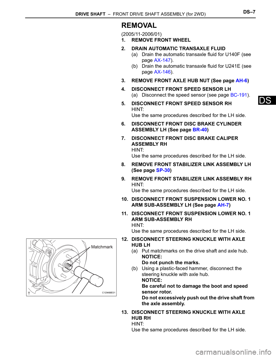
12. DISCONNECT STEERING KNUCKLE WITH AXLE
HUB LH
(a) Put matchmarks on the drive shaft and axle hub.
NOTICE:
Do not punch the marks.
(b) Using a plastic-faced hammer, disconnect the
steering knuckle with axle hub.
NOTICE:
Be careful not to damage the boot and speed
sensor rotor.
Do not excessively push out the drive shaft from
the axle assembly.
13. DISCONNECT STEERING KNUCKLE WITH AXLE
HUB RH
HINT:
Use the same procedures described for the LH side.
C129488E01