Crankshaft position sensor TOYOTA RAV4 2006 Service Owner's Manual
[x] Cancel search | Manufacturer: TOYOTA, Model Year: 2006, Model line: RAV4, Model: TOYOTA RAV4 2006Pages: 2000, PDF Size: 45.84 MB
Page 384 of 2000
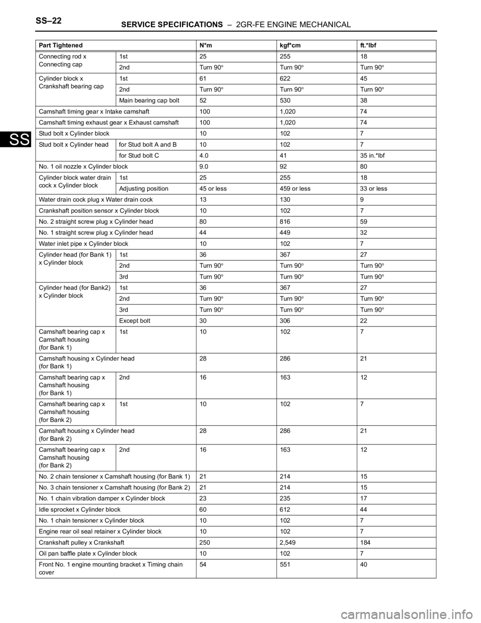
SS–22SERVICE SPECIFICATIONS – 2GR-FE ENGINE MECHANICAL
SS
Connecting rod x
Connecting cap1st 25 255 18
2nd Turn 90
Turn 90Turn 90
Cylinder block x
Crankshaft bearing cap1st 61 622 45
2nd Turn 90
Turn 90Turn 90
Main bearing cap bolt 52 530 38
Camshaft timing gear x Intake camshaft 100 1,020 74
Camshaft timing exhaust gear x Exhaust camshaft 100 1,020 74
Stud bolt x Cylinder block 10 102 7
Stud bolt x Cylinder head for Stud bolt A and B 10 102 7
for Stud bolt C 4.0 41 35 in.*lbf
No. 1 oil nozzle x Cylinder block 9.0 92 80
Cylinder block water drain
cock x Cylinder block1st 25 255 18
Adjusting position 45 or less 459 or less 33 or less
Water drain cock plug x Water drain cock 13 130 9
Crankshaft position sensor x Cylinder block 10 102 7
No. 2 straight screw plug x Cylinder head 80 816 59
No. 1 straight screw plug x Cylinder head 44 449 32
Water inlet pipe x Cylinder block 10 102 7
Cylinder head (for Bank 1)
x Cylinder block1st 36 367 27
2nd Turn 90
Turn 90Turn 90
3rd Turn 90Turn 90Turn 90
Cylinder head (for Bank2)
x Cylinder block1st 36 367 27
2nd Turn 90
Turn 90Turn 90
3rd Turn 90Turn 90Turn 90
Except bolt 30 306 22
Camshaft bearing cap x
Camshaft housing
(for Bank 1)1st 10 102 7
Camshaft housing x Cylinder head
(for Bank 1)28 286 21
Camshaft bearing cap x
Camshaft housing
(for Bank 1)2nd 16 163 12
Camshaft bearing cap x
Camshaft housing
(for Bank 2)1st 10 102 7
Camshaft housing x Cylinder head
(for Bank 2)28 286 21
Camshaft bearing cap x
Camshaft housing
(for Bank 2)2nd 16 163 12
No. 2 chain tensioner x Camshaft housing (for Bank 1) 21 214 15
No. 3 chain tensioner x Camshaft housing (for Bank 2) 21 214 15
No. 1 chain vibration damper x Cylinder block 23 235 17
Idle sprocket x Cylinder block 60 612 44
No. 1 chain tensioner x Cylinder block 10 102 7
Engine rear oil seal retainer x Cylinder block 10 102 7
Crankshaft pulley x Crankshaft 250 2,549 184
Oil pan baffle plate x Cylinder block 10 102 7
Front No. 1 engine mounting bracket x Timing chain
cover54 551 40 Part Tightened N*m kgf*cm ft.*lbf
Page 483 of 2000
2AZ-FE ENGINE CONTROL SYSTEM – SFI SYSTEMES–29
ES
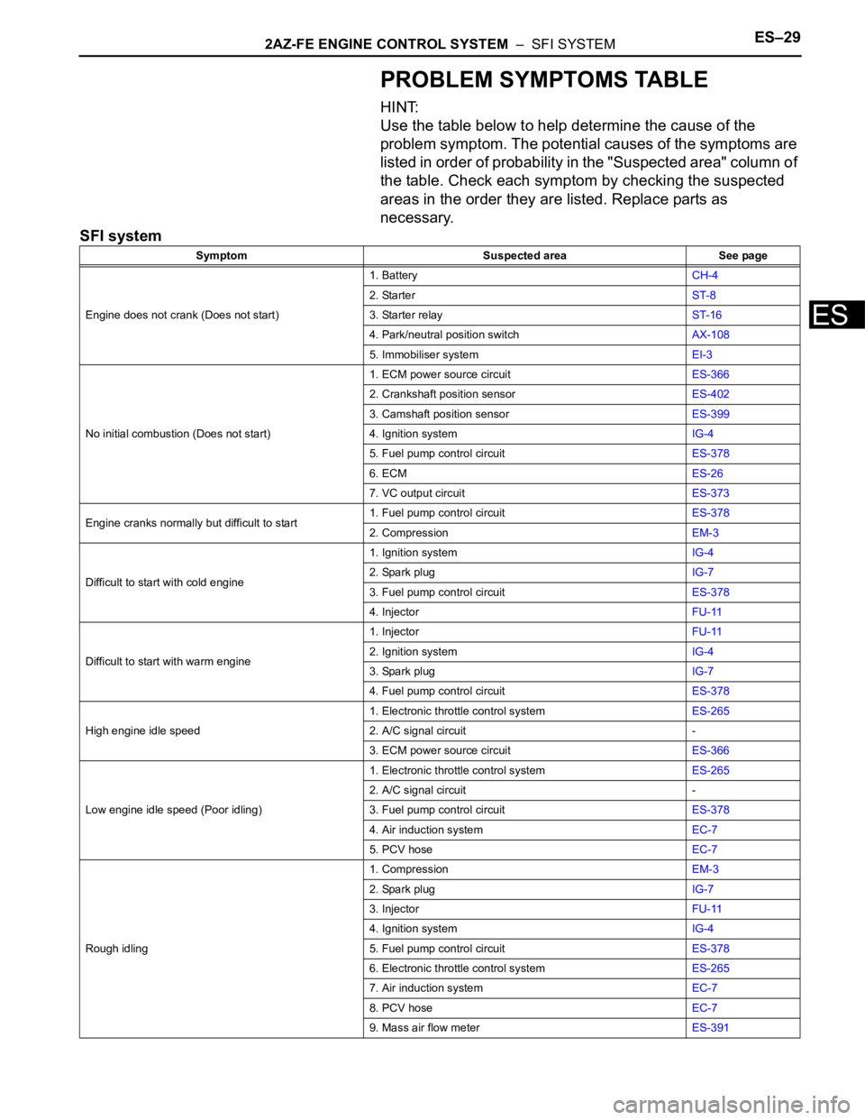
PROBLEM SYMPTOMS TABLE
HINT:
Use the table below to help determine the cause of the
problem symptom. The potential causes of the symptoms are
listed in order of probability in the "Suspected area" column of
the table. Check each symptom by checking the suspected
areas in the order they are listed. Replace parts as
necessary.
SFI system
Symptom Suspected area See page
Engine does not crank (Does not start)1. BatteryCH-4
2. StarterST-8
3. Starter relayST-16
4. Park/neutral position switchAX-108
5. Immobiliser systemEI-3
No initial combustion (Does not start)1. ECM power source circuitES-366
2. Crankshaft position sensorES-402
3. Camshaft position sensorES-399
4. Ignition systemIG-4
5. Fuel pump control circuitES-378
6. ECMES-26
7. VC output circuitES-373
Engine cranks normally but difficult to start1. Fuel pump control circuitES-378
2. CompressionEM-3
Difficult to start with cold engine1. Ignition systemIG-4
2. Spark plugIG-7
3. Fuel pump control circuitES-378
4. InjectorFU-11
Difficult to start with warm engine1. InjectorFU-11
2. Ignition systemIG-4
3. Spark plugIG-7
4. Fuel pump control circuitES-378
High engine idle speed1. Electronic throttle control systemES-265
2. A/C signal circuit -
3. ECM power source circuitES-366
Low engine idle speed (Poor idling)1. Electronic throttle control systemES-265
2. A/C signal circuit -
3. Fuel pump control circuitES-378
4. Air induction systemEC-7
5. PCV hoseEC-7
Rough idling1. CompressionEM-3
2. Spark plugIG-7
3. InjectorFU-11
4. Ignition systemIG-4
5. Fuel pump control circuitES-378
6. Electronic throttle control systemES-265
7. Air induction systemEC-7
8. PCV hoseEC-7
9. Mass air flow meterES-391
Page 486 of 2000
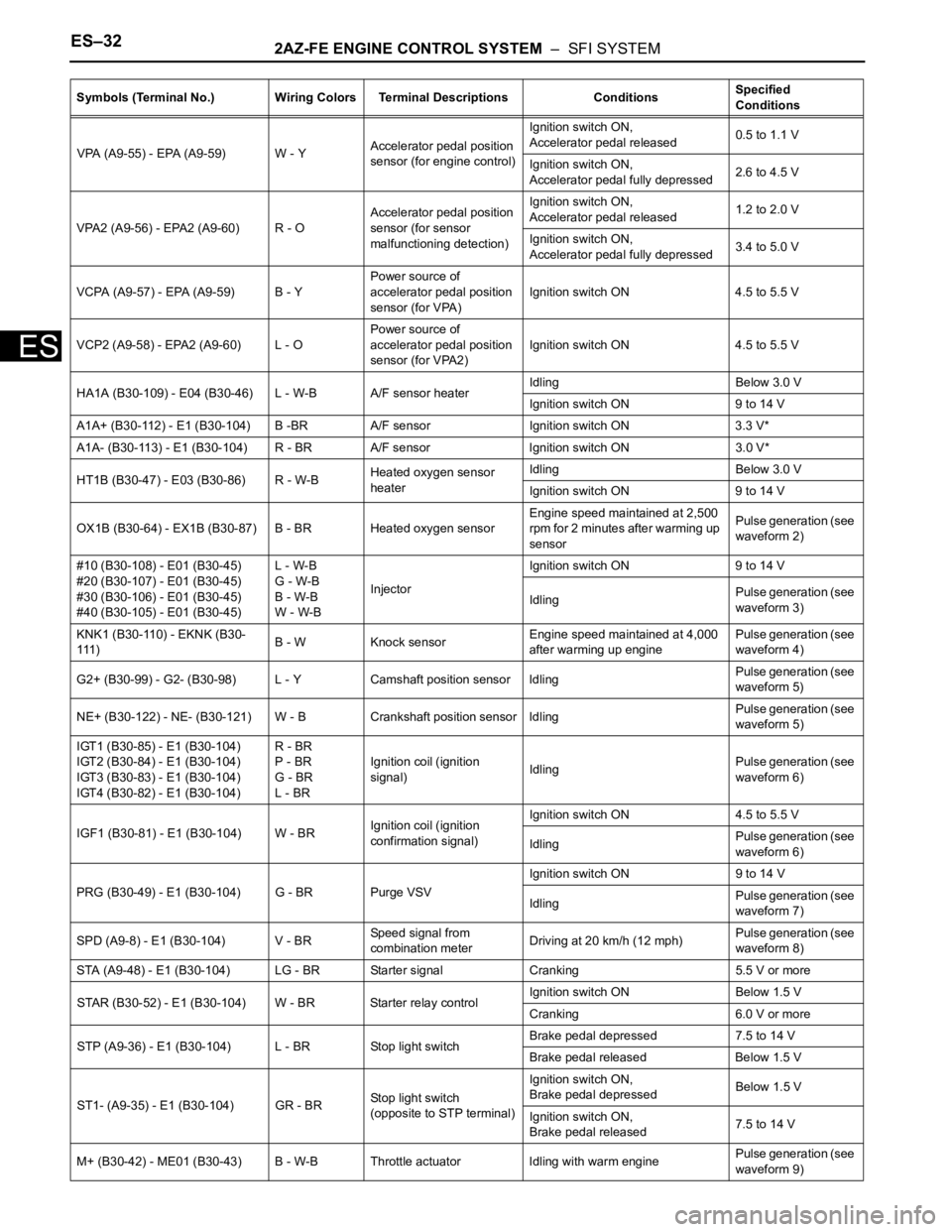
ES–322AZ-FE ENGINE CONTROL SYSTEM – SFI SYSTEM
ES
VPA (A9-55) - EPA (A9-59) W - YAccelerator pedal position
sensor (for engine control)Ignition switch ON,
Accelerator pedal released0.5 to 1.1 V
Ignition switch ON,
Accelerator pedal fully depressed2.6 to 4.5 V
VPA2 (A9-56) - EPA2 (A9-60) R - OAccelerator pedal position
sensor (for sensor
malfunctioning detection)Ignition switch ON,
Accelerator pedal released1.2 to 2.0 V
Ignition switch ON,
Accelerator pedal fully depressed3.4 to 5.0 V
VCPA (A9-57) - EPA (A9-59) B - YPower source of
accelerator pedal position
sensor (for VPA)Ignition switch ON 4.5 to 5.5 V
VCP2 (A9-58) - EPA2 (A9-60) L - OPower source of
accelerator pedal position
sensor (for VPA2)Ignition switch ON 4.5 to 5.5 V
HA1A (B30-109) - E04 (B30-46) L - W-B A/F sensor heaterIdling Below 3.0 V
Ignition switch ON 9 to 14 V
A1A+ (B30-112) - E1 (B30-104) B -BR A/F sensor Ignition switch ON 3.3 V*
A1A- (B30-113) - E1 (B30-104) R - BR A/F sensor Ignition switch ON3.0 V*
HT1B (B30-47) - E03 (B30-86) R - W-BHeated oxygen sensor
heaterIdling Below 3.0 V
Ignition switch ON 9 to 14 V
OX1B (B30-64) - EX1B (B30-87) B - BR Heated oxygen sensorEngine speed maintained at 2,500
rpm for 2 minutes after warming up
sensorPulse generation (see
waveform 2)
#10 (B30-108) - E01 (B30-45)
#20 (B30-107) - E01 (B30-45)
#30 (B30-106) - E01 (B30-45)
#40 (B30-105) - E01 (B30-45)L - W-B
G - W-B
B - W-B
W - W-BInjectorIgnition switch ON 9 to 14 V
IdlingPulse generation (see
waveform 3)
KNK1 (B30-110) - EKNK (B30-
111 )B - W Knock sensorEngine speed maintained at 4,000
after warming up enginePulse generation (see
waveform 4)
G2+ (B30-99) - G2- (B30-98) L - Y Camshaft position sensor IdlingPulse generation (see
waveform 5)
NE+ (B30-122) - NE- (B30-121) W - B Crankshaft position sensor IdlingPulse generation (see
waveform 5)
IGT1 (B30-85) - E1 (B30-104)
IGT2 (B30-84) - E1 (B30-104)
IGT3 (B30-83) - E1 (B30-104)
IGT4 (B30-82) - E1 (B30-104)R - BR
P - BR
G - BR
L - BRIgnition coil (ignition
signal)IdlingPulse generation (see
waveform 6)
IGF1 (B30-81) - E1 (B30-104) W - BRIgnition coil (ignition
confirmation signal)Ignition switch ON 4.5 to 5.5 V
IdlingPulse generation (see
waveform 6)
PRG (B30-49) - E1 (B30-104) G - BR Purge VSVIgnition switch ON 9 to 14 V
IdlingPulse generation (see
waveform 7)
SPD (A9-8) - E1 (B30-104) V - BRSpeed signal from
combination meterDriving at 20 km/h (12 mph)Pulse generation (see
waveform 8)
STA (A9-48) - E1 (B30-104) LG - BR Starter signal Cranking 5.5 V or
more
STAR (B30-52) - E1 (B30-104) W - BR Starter relay controlIgnition switch ON Below 1.5 V
Cranking 6.0 V or more
STP (A9-36) - E1 (B30-104) L - BR Stop light switchBrake pedal depressed 7.5 to 14 V
Brake pedal released Below 1.5 V
ST1- (A9-35) - E1 (B30-104) GR - BRStop light switch
(opposite to STP terminal)Ignition switch ON,
Brake pedal depressedBelow 1.5 V
Ignition switch ON,
Brake pedal released7.5 to 14 V
M+ (B30-42) - ME01 (B30-43) B - W-B Throttle actuator Idling with warm enginePulse generation (see
waveform 9) Symbols (Terminal No.) Wiring Colors Terminal Descriptions ConditionsSpecified
Conditions
Page 489 of 2000
2AZ-FE ENGINE CONTROL SYSTEM – SFI SYSTEMES–35
ES
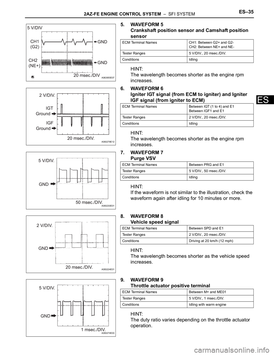
5. WAVEFORM 5
Crankshaft position sensor and Camshaft position
sensor
HINT:
The wavelength becomes shorter as the engine rpm
increases.
6. WAVEFORM 6
Igniter IGT signal (from ECM to igniter) and Igniter
IGF signal (from igniter to ECM)
HINT:
The wavelength becomes shorter as the engine rpm
increases.
7. WAVEFORM 7
Purge VSV
HINT:
If the waveform is not similar to the illustration, check the
waveform again after idling for 10 minutes or more.
8. WAVEFORM 8
Vehicle speed signal
HINT:
The wavelength becomes shorter as the vehicle speed
increases.
9. WAVEFORM 9
Throttle actuator positive terminal
HINT:
The duty ratio varies depending on the throttle actuator
operation.
A063955E07
ECM Terminal Names CH1: Between G2+ and G2-
CH2: Between NE+ and NE-
Tester Ranges 5 V/DIV., 20 msec./DIV.
Conditions Idling
A093278E12
ECM Terminal Names Between IGT (1 to 4) and E1
Between IGF1 and E1
Tester Ranges 2 V/DIV., 20 msec./DIV.
Conditions Idling
A093230E01
ECM Terminal Names Between PRG and E1
Tester Ranges 5 V/DIV., 50 msec./DIV.
Conditions Idling
A093224E01
ECM Terminal Names Between SPD and E1
Tester Ranges 2 V/DIV., 20 msec./DIV.
Conditions Driving at 20 km/h (12 mph)
A093274E03
ECM Terminal Names Between M+ and ME01
Tester Ranges 5 V/DIV., 1 msec./DIV.
Conditions Idling with warm engine
Page 556 of 2000
ES–322GR-FE ENGINE CONTROL SYSTEM – SFI SYSTEM
ES
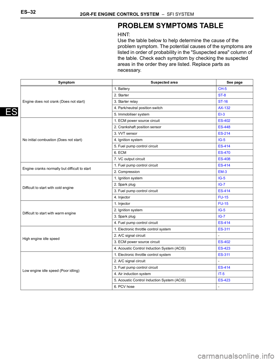
PROBLEM SYMPTOMS TABLE
HINT:
Use the table below to help determine the cause of the
problem symptom. The potential causes of the symptoms are
listed in order of probability in the "Suspected area" column of
the table. Check each symptom by checking the suspected
areas in the order they are listed. Replace parts as
necessary.
Symptom Suspected area See page
Engine does not crank (Does not start)1. BatteryCH-5
2. StarterST-8
3. Starter relayST-16
4. Park/neutral position switchAX-132
5. Immobiliser systemEI-3
No initial combustion (Does not start)1. ECM power source circuitES-402
2. Crankshaft position sensorES-448
3. VVT sensorES-214
4. Ignition systemIG-5
5. Fuel pump control circuitES-414
6. ECMES-470
7. VC output circuitES-408
Engine cranks normally but difficult to start1. Fuel pump control circuitES-414
2. CompressionEM-3
Difficult to start with cold engine1. Ignition systemIG-5
2. Spark plugIG-7
3. Fuel pump control circuitES-414
4. InjectorFU-15
Difficult to start with warm engine1. InjectorFU-15
2. Ignition systemIG-5
3. Spark plugIG-7
4. Fuel pump control circuitES-414
High engine idle speed1. Electronic throttle control systemES-311
2. A/C signal circuit -
3. ECM power source circuitES-402
4. Acoustic Control Induction System (ACIS)ES-423
Low engine idle speed (Poor idling)1. Electronic throttle control systemES-311
2. A/C signal circuit -
3. Fuel pump control circuitES-414
4. Air induction systemIT-5
5. Acoustic Control Induction System (ACIS)ES-423
6. PCV hose -
Page 560 of 2000
ES–362GR-FE ENGINE CONTROL SYSTEM – SFI SYSTEM
ES
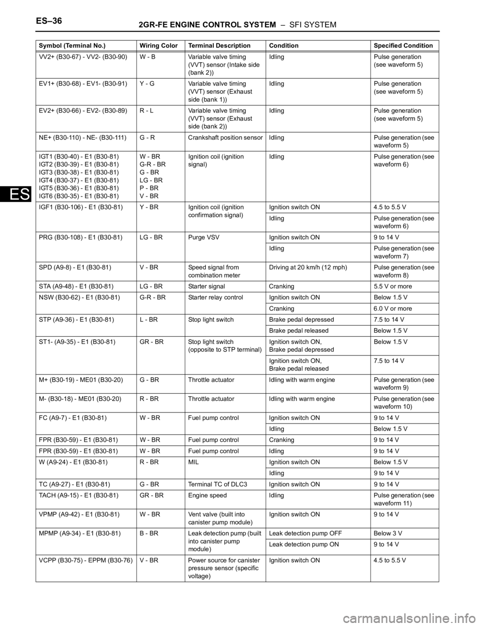
VV2+ (B30-67) - VV2- (B30-90) W - B Variable valve timing
(VVT) sensor (Intake side
(bank 2))Idling Pulse generation
(see waveform 5)
EV1+ (B30-68) - EV1- (B30-91) Y - G Variable valve timing
(VVT) sensor (Exhaust
side (bank 1))Idling Pulse generation
(see waveform 5)
EV2+ (B30-66) - EV2- (B30-89) R - L Variable valve timing
(VVT) sensor (Exhaust
side (bank 2))Idling Pulse generation
(see waveform 5)
NE+ (B30-110) - NE- (B30-111) G - R Crankshaft position sensor Idling Pulse generation (see
waveform 5)
IGT1 (B30-40) - E1 (B30-81)
IGT2 (B30-39) - E1 (B30-81)
IGT3 (B30-38) - E1 (B30-81)
IGT4 (B30-37) - E1 (B30-81)
IGT5 (B30-36) - E1 (B30-81)
IGT6 (B30-35) - E1 (B30-81)W - BR
G-R - BR
G - BR
LG - BR
P - BR
V - BRIgnition coil (ignition
signal)Idling Pulse generation (see
waveform 6)
IGF1 (B30-106) - E1 (B30-81) Y - BR Ignition coil (ignition
confirmation signal)Ignition switch ON 4.5 to 5.5 V
Idling Pulse generation (see
waveform 6)
PRG (B30-108) - E1 (B30-81) LG - BR Purge VSV Ignition switch ON 9 to 14 V
Idling Pulse generation (see
waveform 7)
SPD (A9-8) - E1 (B30-81) V - BR Speed signal from
combination meterDriving at 20 km/h (12 mph) Pulse generation (see
waveform 8)
STA (A9-48) - E1 (B30-81) LG - BR Starter signal Cranking 5.5 V or more
NSW (B30-62) - E1 (B30-81) G-R - BR Starter relay control Ignition switch ON Below 1.5 V
Cranking 6.0 V or more
STP (A9-36) - E1 (B30-81) L - BR Stop light switch Brake pedal depressed 7.5 to 14 V
Brake pedal released Below 1.5 V
ST1- (A9-35) - E1 (B30-81) GR - BR Stop light switch
(opposite to STP terminal)Ignition switch ON,
Brake pedal depressedBelow 1.5 V
Ignition switch ON,
Brake pedal released7.5 to 14 V
M+ (B30-19) - ME01 (B30-20) G - BR Throttle actuator Idling with warm engine Pulse generation (see
waveform 9)
M- (B30-18) - ME01 (B30-20) R - BR Throttle actuator Idling with warm engine Pulse generation (see
waveform 10)
FC (A9-7) - E1 (B30-81) W - BR Fuel pump control Ignition switch ON 9 to 14 V
Idling Below 1.5 V
FPR (B30-59) - E1 (B30-81) W - BR Fuel pump control Cranking 9 to 14 V
FPR (B30-59) - E1 (B30-81) W - BR Fuel pump control Idling 9 to 14 V
W (A9-24) - E1 (B30-81) R - BR MIL Ignition switch ON Below 1.5 V
Idling 9 to 14 V
TC (A9-27) - E1 (B30-81) G - BR Terminal TC of DLC3 Ignition switch ON 9 to 14 V
TACH (A9-15) - E1 (B30-81) GR - BR Engine speed Idling Pulse generation (see
waveform 11)
VPMP (A9-42) - E1 (B30-81) W - BR Vent valve (built into
canister pump module)Ignition switch ON 9 to 14 V
MPMP (A9-34) - E1 (B30-81) B - BR Leak detection pump (built
into canister pump
module)Leak detection pump OFF Below 3 V
Leak detection pump ON 9 to 14 V
VCPP (B30-75) - EPPM (B30-76) V - BR Power source for canister
pressure sensor (specific
voltage)Ignition switch ON 4.5 to 5.5 V Symbol (Terminal No.) Wiring Color Terminal Description Condition Specified Condition
Page 562 of 2000
ES–382GR-FE ENGINE CONTROL SYSTEM – SFI SYSTEM
ES
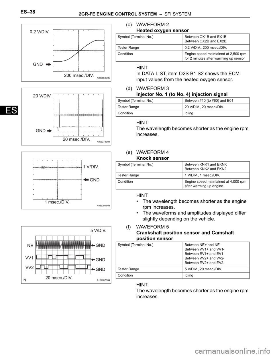
(c) WAVEFORM 2
Heated oxygen sensor
HINT:
In DATA LIST, item O2S B1 S2 shows the ECM
input values from the heated oxygen sensor.
(d) WAVEFORM 3
Injector No. 1 (to No. 4) injection signal
HINT:
The wavelength becomes shorter as the engine rpm
increases.
(e) WAVEFORM 4
Knock sensor
HINT:
• The wavelength becomes shorter as the engine
rpm increases.
• The waveforms and amplitudes displayed differ
slightly depending on the vehicle.
(f) WAVEFORM 5
Crankshaft position sensor and Camshaft
position sensor
HINT:
The wavelength becomes shorter as the engine rpm
increases.
A088863E05
Symbol (Terminal No.) Between OX1B and EX1B
Between OX2B and EX2B
Tester Range 0.2 V/DIV., 200 msec./DIV.
Condition Engine speed maintained at 2,500 rpm
for 2 minutes after warming up sensor
A093279E04
Symbol (Terminal No.) Between #10 (to #60) and E01
Tester Range 20 V/DIV., 20 msec./DIV.
Condition Idling
A085286E03
Symbol (Terminal No.) Between KNK1 and EKNK
Between KNK2 and EKN2
Tester Range 1 V/DIV., 1 msec./DIV.
Condition Engine speed maintained at 4,000 rpm
after warming up engine
A122767E04
Symbol (Terminal No.) Between NE+ and NE-
Between VV1+ and VV1-
Between EV1+ and EV1-
Between VV2+ and VV2-
Between EV2+ and EV2-
Tester Range 5 V/DIV., 20 msec./DIV.
Condition Idling
Page 583 of 2000
EM–262AZ-FE ENGINE MECHANICAL – TIMING CHAIN
EM
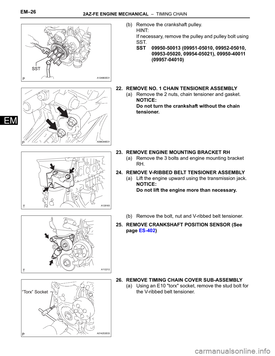
(b) Remove the crankshaft pulley.
HINT:
If necessary, remove the pulley and pulley bolt using
SST.
SST 09950-50013 (09951-05010, 09952-05010,
09953-05020, 09954-05021), 09950-40011
(09957-04010)
22. REMOVE NO. 1 CHAIN TENSIONER ASSEMBLY
(a) Remove the 2 nuts, chain tensioner and gasket.
NOTICE:
Do not turn the crankshaft without the chain
tensioner.
23. REMOVE ENGINE MOUNTING BRACKET RH
(a) Remove the 3 bolts and engine mounting bracket
RH.
24. REMOVE V-RIBBED BELT TENSIONER ASSEMBLY
(a) Lift the engine upward using the transmission jack.
NOTICE:
Do not lift the engine more than necessary.
(b) Remove the bolt, nut and V-ribbed belt tensioner.
25. REMOVE CRANKSHAFT POSITION SENSOR (See
page ES-402)
26. REMOVE TIMING CHAIN COVER SUB-ASSEMBLY
(a) Using an E10 "torx" socket, remove the stud bolt for
the V-ribbed belt tensioner.
A124860E01
A098348E01
A128165
A112212
A014253E03
Page 584 of 2000
2AZ-FE ENGINE MECHANICAL – TIMING CHAINEM–27
EM
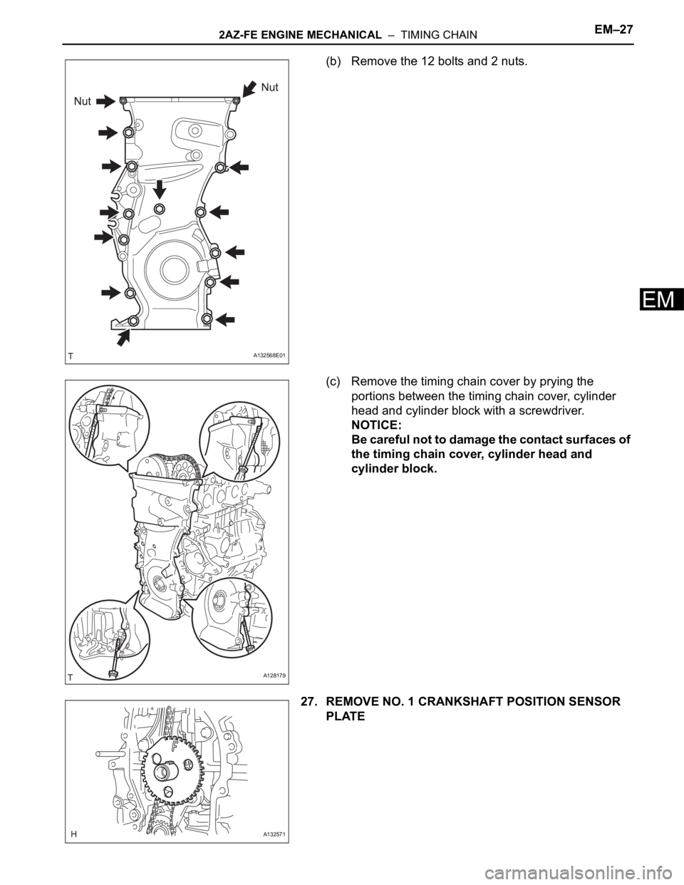
(b) Remove the 12 bolts and 2 nuts.
(c) Remove the timing chain cover by prying the
portions between the timing chain cover, cylinder
head and cylinder block with a screwdriver.
NOTICE:
Be careful not to damage the contact surfaces of
the timing chain cover, cylinder head and
cylinder block.
27. REMOVE NO. 1 CRANKSHAFT POSITION SENSOR
PLATE
A132568E01
A128179
A132571
Page 592 of 2000
2AZ-FE ENGINE MECHANICAL – TIMING CHAINEM–35
EM
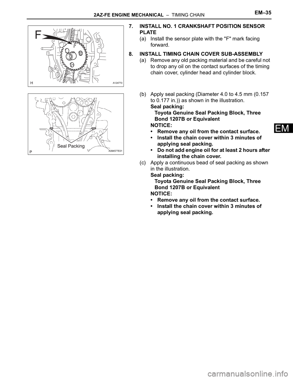
7. INSTALL NO. 1 CRANKSHAFT POSITION SENSOR
PLATE
(a) Install the sensor plate with the "F" mark facing
forward.
8. INSTALL TIMING CHAIN COVER SUB-ASSEMBLY
(a) Remove any old packing material and be careful not
to drop any oil on the contact surfaces of the timing
chain cover, cylinder head and cylinder block.
(b) Apply seal packing (Diameter 4.0 to 4.5 mm (0.157
to 0.177 in.)) as shown in the illustration.
Seal packing:
Toyota Genuine Seal Packing Block, Three
Bond 1207B or Equivalent
NOTICE:
• Remove any oil from the contact surface.
• Install the chain cover within 3 minutes of
applying seal packing.
• Do not add engine oil for at least 2 hours after
installing the chain cover.
(c) Apply a continuous bead of seal packing as shown
in the illustration.
Seal packing:
Toyota Genuine Seal Packing Block, Three
Bond 1207B or Equivalent
NOTICE:
• Remove any oil from the contact surface.
• Install the chain cover within 3 minutes of
applying seal packing.
A124770
A094577E01