park assist TOYOTA RAV4 2006 Service Repair Manual
[x] Cancel search | Manufacturer: TOYOTA, Model Year: 2006, Model line: RAV4, Model: TOYOTA RAV4 2006Pages: 2000, PDF Size: 45.84 MB
Page 1517 of 2000

BC–14BRAKE CONTROL – VEHICLE STABILITY CONTROL SYSTEM
BC
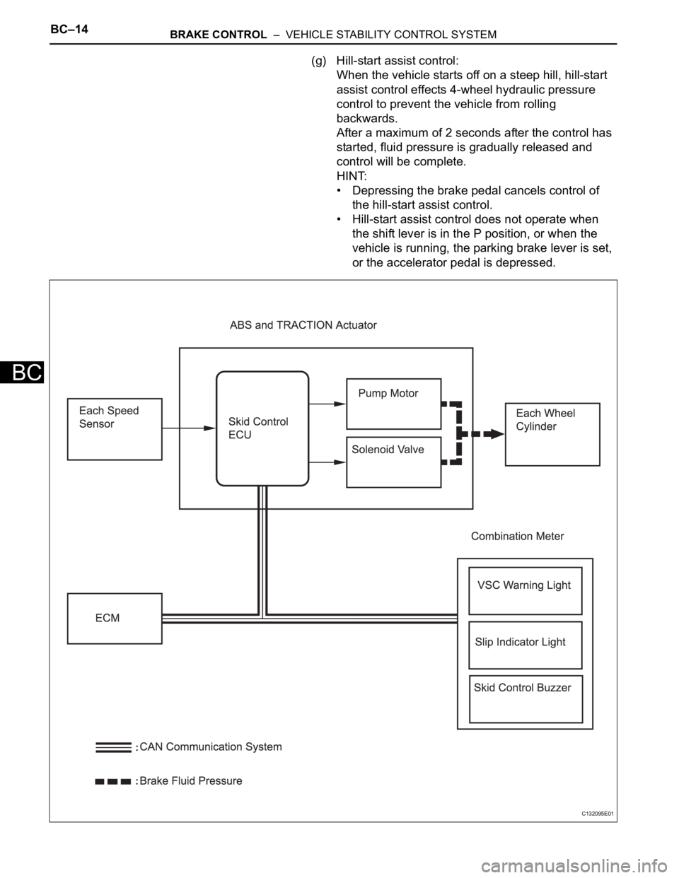
(g) Hill-start assist control:
When the vehicle starts off on a steep hill, hill-start
assist control effects 4-wheel hydraulic pressure
control to prevent the vehicle from rolling
backwards.
After a maximum of 2 seconds after the control has
started, fluid pressure is gradually released and
control will be complete.
HINT:
• Depressing the brake pedal cancels control of
the hill-start assist control.
• Hill-start assist control does not operate when
the shift lever is in the P position, or when the
vehicle is running, the parking brake lever is set,
or the accelerator pedal is depressed.
C132095E01
Page 1523 of 2000

BC–20BRAKE CONTROL – VEHICLE STABILITY CONTROL SYSTEM
BC
HINT:
*1: w/ Downhill assist control
*2: for 2WD w/ AUTO LSD
Steering Sensor • Detects the steering extent and direction and sends
signals to the skid control ECU via CAN communication
• Has a magnetic resistance element which detects the
rotation of the magnet housed in the detection gear in
order to detect the changes in magnetic resistance and
the steering amount and direction
Yaw Rate and Deceleration Sensor • Yaw rate sensor detects the vehicle's angular velocity
(yaw rate) in the vertical direction based on the extent
and direction of the deflection of the piezoelectric
ceramics
• Deceleration sensor measures the capacity of the
condenser that changes the distance between the
electrodes depending on G force, which occurs when
the vehicle is accelerated, and converts the measured
value into electrical signals
• Sends signals to the skid control ECU via CAN
communication
Master Cylinder Pressure Sensor • Detects the brake fluid pressure in the master cylinder
• Housed in the ABS and TRACTION actuator
ECM• Controls the engine output when TRC and VSC are
operating with the skid control ECU via CAN
communication
Downhill Assist Control switch*1 Allows the driver to turn downhill assist control ON and OFF
AUTO LSD switch*2 Allows the driver to turn AUTO LSD ON and OFF
Combination Meter ABS Warning Light • Illuminates to inform the driver that a malfunction in the
ABS has occurred
• Blinks to indicate DTCs that relate to the ABS
VSC Warning Light • Illuminates to inform the driver that a malfunction in the
VSC system has occurred
• Blinks to indicate DTCs that relate to the VSC
Brake Warning light • Illuminates to inform the driver that the parking brake is
ON when the system is normal, and when the brake
fluid has decreased
• Illuminates to inform the driver that a malfunction in the
EBD has occurred
Slip Indicator Light • Blinks to inform the driver that TRC, VSC, downhill
assist control and hill-start assist control are operating
• Illuminates to inform the driver that a malfunction has
occurred in the TRC or VSC system
AUTO LSD Indicator Light*2 Lights up to inform the driver when AUTO LSD operation is
possible
Downhill Assist Control Indicator
Light*1Lights up to inform the driver when downhill assist control
operation is possible
Skid Control Buzzer • Intermittently sounds to inform the driver that the VSC is
operating
• Housed in the combination meter Components Functions
Page 1537 of 2000

BC–34BRAKE CONTROL – VEHICLE STABILITY CONTROL SYSTEM
BC
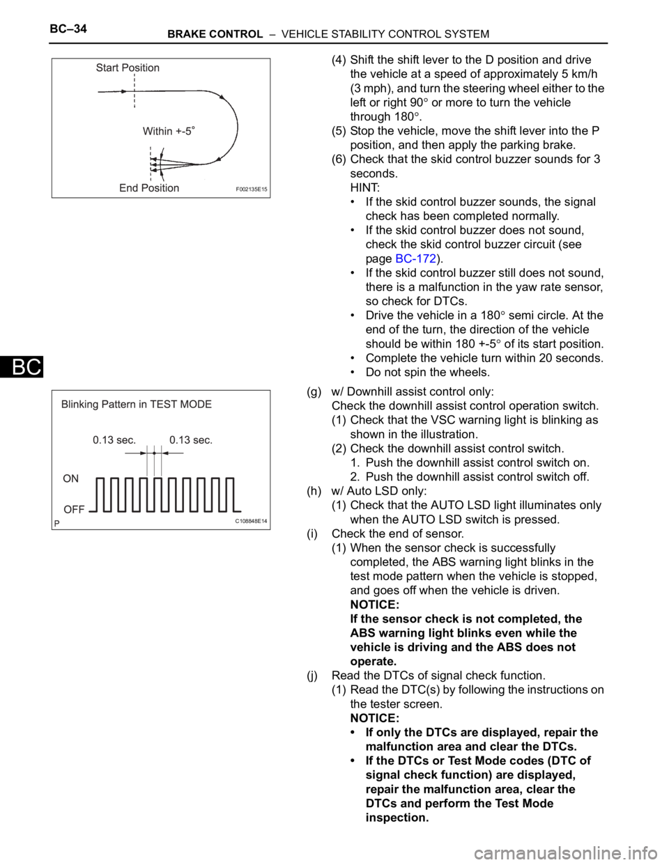
(4) Shift the shift lever to the D position and drive
the vehicle at a speed of approximately 5 km/h
(3 mph), and turn the steering wheel either to the
left or right 90
or more to turn the vehicle
through 180
.
(5) Stop the vehicle, move the shift lever into the P
position, and then apply the parking brake.
(6) Check that the skid control buzzer sounds for 3
seconds.
HINT:
• If the skid control buzzer sounds, the signal
check has been completed normally.
• If the skid control buzzer does not sound,
check the skid control buzzer circuit (see
page BC-172).
• If the skid control buzzer still does not sound,
there is a malfunction in the yaw rate sensor,
so check for DTCs.
• Drive the vehicle in a 180
semi circle. At the
end of the turn, the direction of the vehicle
should be within 180 +-5
of its start position.
• Complete the vehicle turn within 20 seconds.
• Do not spin the wheels.
(g) w/ Downhill assist control only:
Check the downhill assist control operation switch.
(1) Check that the VSC warning light is blinking as
shown in the illustration.
(2) Check the downhill assist control switch.
1. Push the downhill assist control switch on.
2. Push the downhill assist control switch off.
(h) w/ Auto LSD only:
(1) Check that the AUTO LSD light illuminates only
when the AUTO LSD switch is pressed.
(i) Check the end of sensor.
(1) When the sensor check is successfully
completed, the ABS warning light blinks in the
test mode pattern when the vehicle is stopped,
and goes off when the vehicle is driven.
NOTICE:
If the sensor check is not completed, the
ABS warning light blinks even while the
vehicle is driving and the ABS does not
operate.
(j) Read the DTCs of signal check function.
(1) Read the DTC(s) by following the instructions on
the tester screen.
NOTICE:
• If only the DTCs are displayed, repair the
malfunction area and clear the DTCs.
• If the DTCs or Test Mode codes (DTC of
signal check function) are displayed,
repair the malfunction area, clear the
DTCs and perform the Test Mode
inspection.
F002135E15
C108848E14
Page 1541 of 2000

BC–38BRAKE CONTROL – VEHICLE STABILITY CONTROL SYSTEM
BC
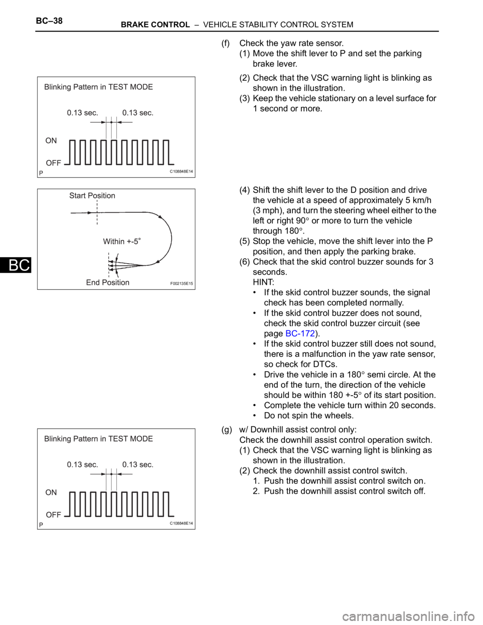
(f) Check the yaw rate sensor.
(1) Move the shift lever to P and set the parking
brake lever.
(2) Check that the VSC warning light is blinking as
shown in the illustration.
(3) Keep the vehicle stationary on a level surface for
1 second or more.
(4) Shift the shift lever to the D position and drive
the vehicle at a speed of approximately 5 km/h
(3 mph), and turn the steering wheel either to the
left or right 90
or more to turn the vehicle
through 180
.
(5) Stop the vehicle, move the shift lever into the P
position, and then apply the parking brake.
(6) Check that the skid control buzzer sounds for 3
seconds.
HINT:
• If the skid control buzzer sounds, the signal
check has been completed normally.
• If the skid control buzzer does not sound,
check the skid control buzzer circuit (see
page BC-172).
• If the skid control buzzer still does not sound,
there is a malfunction in the yaw rate sensor,
so check for DTCs.
• Drive the vehicle in a 180
semi circle. At the
end of the turn, the direction of the vehicle
should be within 180 +-5
of its start position.
• Complete the vehicle turn within 20 seconds.
• Do not spin the wheels.
(g) w/ Downhill assist control only:
Check the downhill assist control operation switch.
(1) Check that the VSC warning light is blinking as
shown in the illustration.
(2) Check the downhill assist control switch.
1. Push the downhill assist control switch on.
2. Push the downhill assist control switch off.
C108848E14
F002135E15
C108848E14
Page 1552 of 2000

BRAKE CONTROL – VEHICLE STABILITY CONTROL SYSTEMBC–49
BC
• *4: w/ 16-inch disc
• The DTCs can be read by connecting SST (09843-
18040) between the TC and CG terminals of the
DLC3 and observing the blinking pattern of the ABS
and VSC warning lights, or by using an intelligent
tester (see page BC-47).
• This system has a sensor signal check function (see
page BC-28).
2. CHECK WARNING LIGHT AND INDICATOR LIGHT
(a) Release the parking brake lever.
NOTICE:
Before releasing the parking brake lever, set
chocks to hold the vehicle for safety.
HINT:
When the parking brake is applied or the brake fluid
level is low, the brake warning light comes on.
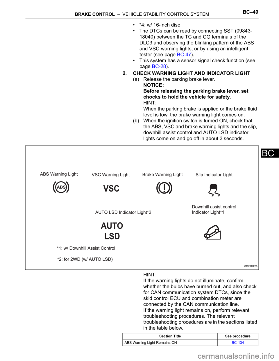
(b) When the ignition switch is turned ON, check that
the ABS, VSC and brake warning lights and the slip,
downhill assist control and AUTO LSD indicator
lights come on and go off in about 3 seconds.
HINT:
If the warning lights do not illuminate, confirm
whether the bulbs have burned out, and also check
for CAN communication system DTCs, since the
skid control ECU and combination meter are
connected by the CAN communication line.
If the warning light remains on, perform relevant
troubleshooting procedures. The relevant
troubleshooting procedures are in the sections listed
in the table below.
C132117E03
Section Title See procedure
ABS Warning Light Remains ONBC-134
Page 1559 of 2000

BC–56BRAKE CONTROL – VEHICLE STABILITY CONTROL SYSTEM
BC
DATA LIST / ACTIVE TEST
1. READ DATA LIST
HINT:
Using the intelligent tester's DATA LIST allows switch,
sensor, actuator and other item values to be read without
out removing any parts. Reading the DATA LIST early in
troubleshooting is one way to save time.
(a) Connect the intelligent tester (with CAN VIM) to the
DLC3.
(b) Turn the ignition switch ON.
(c) Turn the intelligent tester on.
(d) Read the DATA LIST according to the display on the
tester.
Skid control ECU
Tester Display Measurement Item/Range Normal Condition Diagnostic Note
ABS WARN LAMP ABS warning light / ON or OFF ON: ABS warning light ON
OFF: ABS warning light OFF-
VSC WARN LAMP VSC warning light / ON or OFF ON: VSC warning light ON
OFF: VSC warning light OFF-
BRAKE WARN LAMP Brake warning light / ON or OFF ON: Brake warning light ON
OFF: Brake warning light OFF-
SLIP INDI LAMP Slip indicator light / ON or OFF ON: Slip indicator light ON
OFF: Slip indicator light OFF-
D-HILL LIGHT*9 Downhill assist control indicator
light / ON or OFFON: Downhill assist control switch
ON
OFF: Downhill assist control
switch OFF-
AUTO LSD LAMP*10 AUTO LSD indicator light / ON or
OFFON: Traction control switch ON
OFF: Traction control switch OFF-
BUZZER Skid control buzzer / ON or OFF ON: Buzzer ON
OFF: Buzzer OFF-
STOP LAMP SW Stop light switch / ON or OFF ON: Brake pedal depressed
OFF: Brake pedal released-
PARKING BRAKE SW Parking brake switch / ON or OFF ON: Parking brake applied
OFF: Parking brake released-
BRK PEDAL SW Brake pedal load sensing switch /
ON or OFFON: Brake pedal depressed
beyond the specified point
OFF: Brake pedal not depressed
beyond the specified point-
IDLE SW Main idle switch / ON or OFF ON: Accelerator pedal released
OFF: Accelerator pedal
depressed-
DAC SW*9 Downhill assist control switch /
ON or OFFON: Downhill assist control switch
ON
ON: Downhill assist control switch
ON-
AUTO LSD SW*10 AUTO LSD switch / ON or OFF ON: AUTO LSD switch ON
ON: AUTO LSD switch ON-
GEAR POSITION Gear position information / P/N,
R, 1st-6th, FAIL, NOT R--
LEVER POSITION Shift lever position information / P/
N, R, D/M, 1st-6th/B, FAIL--
SHIFT INFO Shift information / ON or OFF ON: During gear change -
MAS CYL PRESS 1 Master cylinder pressure sensor 1
reading / min.: 0 V, max.: 5 VWhen brake pedal released: 0.3
to 0.9 VReading increases when brake
pedal depressed
ZERO M/C SEN Memorized zero point value of
master cylinder pressure sensor /
min.: -12.5 MPa, max.: 12.4 MPaMin.: -12.5 MPa
Max.: 12.4 MPa-