check engine TOYOTA RAV4 2006 Service Owner's Manual
[x] Cancel search | Manufacturer: TOYOTA, Model Year: 2006, Model line: RAV4, Model: TOYOTA RAV4 2006Pages: 2000, PDF Size: 45.84 MB
Page 341 of 2000

CH–62AZ-FE CHARGING – CHARGING SYSTEM
CH
8. INSPECT CHARGING CIRCUIT WITH LOAD
(a) With the engine running at 2,000 rpm, turn the high
beam headlights ON and turn the heater blower
switch to the "HI" position.
(b) Check the reading on the ammeter.
Standard amperage:
30 A or more
If the ammeter reading is less than the standard
amperage, repair the generator.
HINT:
If the battery is fully charged, the indication will
sometimes be less than the standard amperage. If
this is the case, add more electrical load (operate
the wipers, rear window defogger, etc.) and check
the reading on the ammeter again.
Page 440 of 2000
EI–4ENGINE IMMOBILISER – ENGINE IMMOBILISER SYSTEM
EI
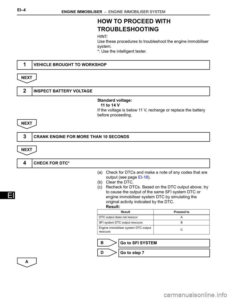
HOW TO PROCEED WITH
TROUBLESHOOTING
HINT:
Use these procedures to troubleshoot the engine immobiliser
system.
*: Use the intelligent tester.
NEXT
Standard voltage:
11 to 14 V
If the voltage is below 11 V, recharge or replace the battery
before proceeding.
NEXT
NEXT
(a) Check for DTCs and make a note of any codes that are
output (see page EI-18).
(b) Clear the DTC.
(c) Recheck for DTCs. Based on the DTC output above, try
to cause the output of the same SFI system DTC or
engine immobiliser system DTC by simulating the
original activity indicated by the DTC.
Result:
B
D
A
1VEHICLE BROUGHT TO WORKSHOP
2INSPECT BATTERY VOLTAGE
3CRANK ENGINE FOR MORE THAN 10 SECONDS
4CHECK FOR DTC*
Result Proceed to
DTC output does not reoccur A
SFI system DTC output reoccurs B
Engine immobiliser system DTC output
reoccursC
Go to SFI SYSTEM
Go to step 7
Page 463 of 2000
2AZ-FE ENGINE CONTROL SYSTEM – SFI SYSTEMES–9
ES
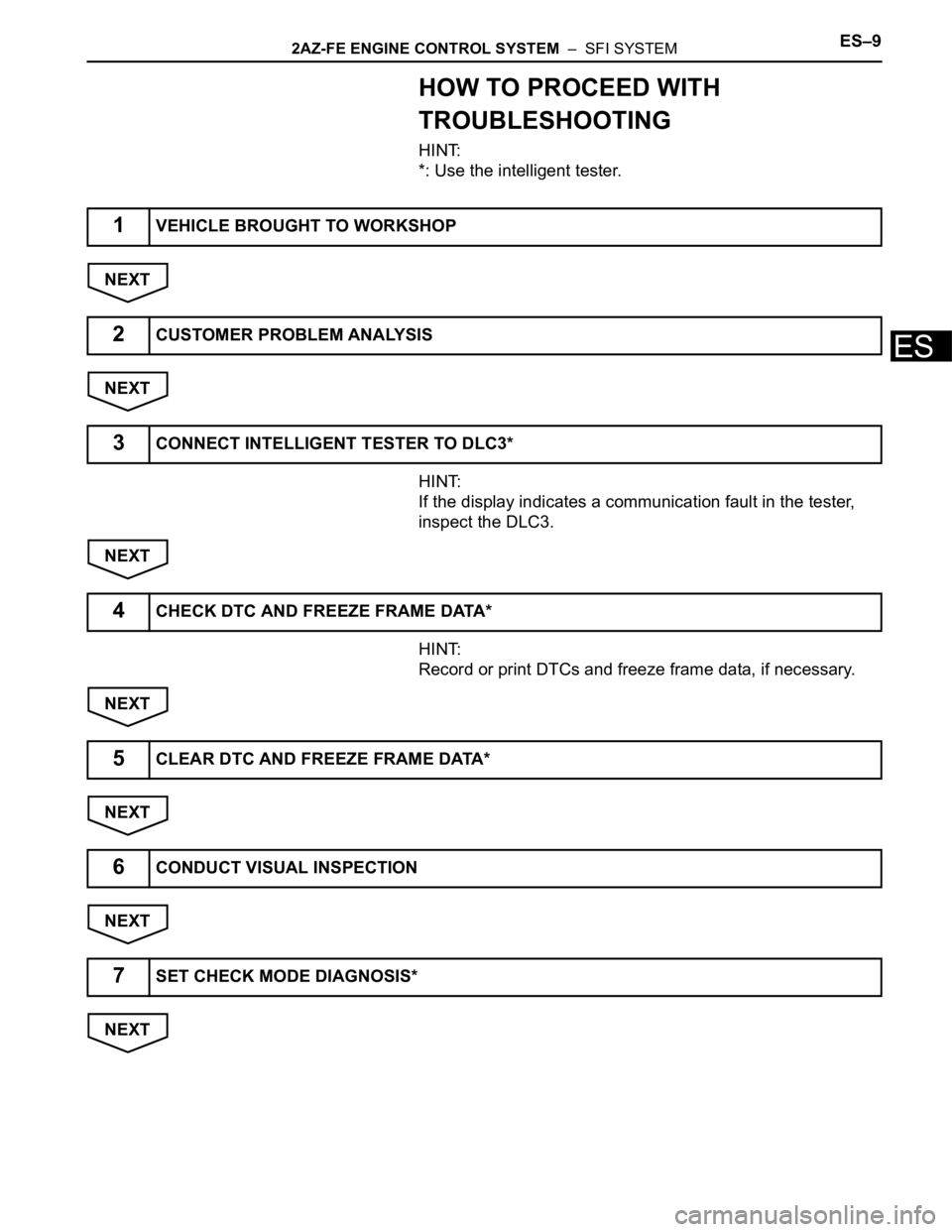
HOW TO PROCEED WITH
TROUBLESHOOTING
HINT:
*: Use the intelligent tester.
NEXT
NEXT
HINT:
If the display indicates a communication fault in the tester,
inspect the DLC3.
NEXT
HINT:
Record or print DTCs and freeze frame data, if necessary.
NEXT
NEXT
NEXT
NEXT
1VEHICLE BROUGHT TO WORKSHOP
2CUSTOMER PROBLEM ANALYSIS
3CONNECT INTELLIGENT TESTER TO DLC3*
4CHECK DTC AND FREEZE FRAME DATA*
5CLEAR DTC AND FREEZE FRAME DATA*
6CONDUCT VISUAL INSPECTION
7SET CHECK MODE DIAGNOSIS*
Page 464 of 2000
ES–102AZ-FE ENGINE CONTROL SYSTEM – SFI SYSTEM
ES
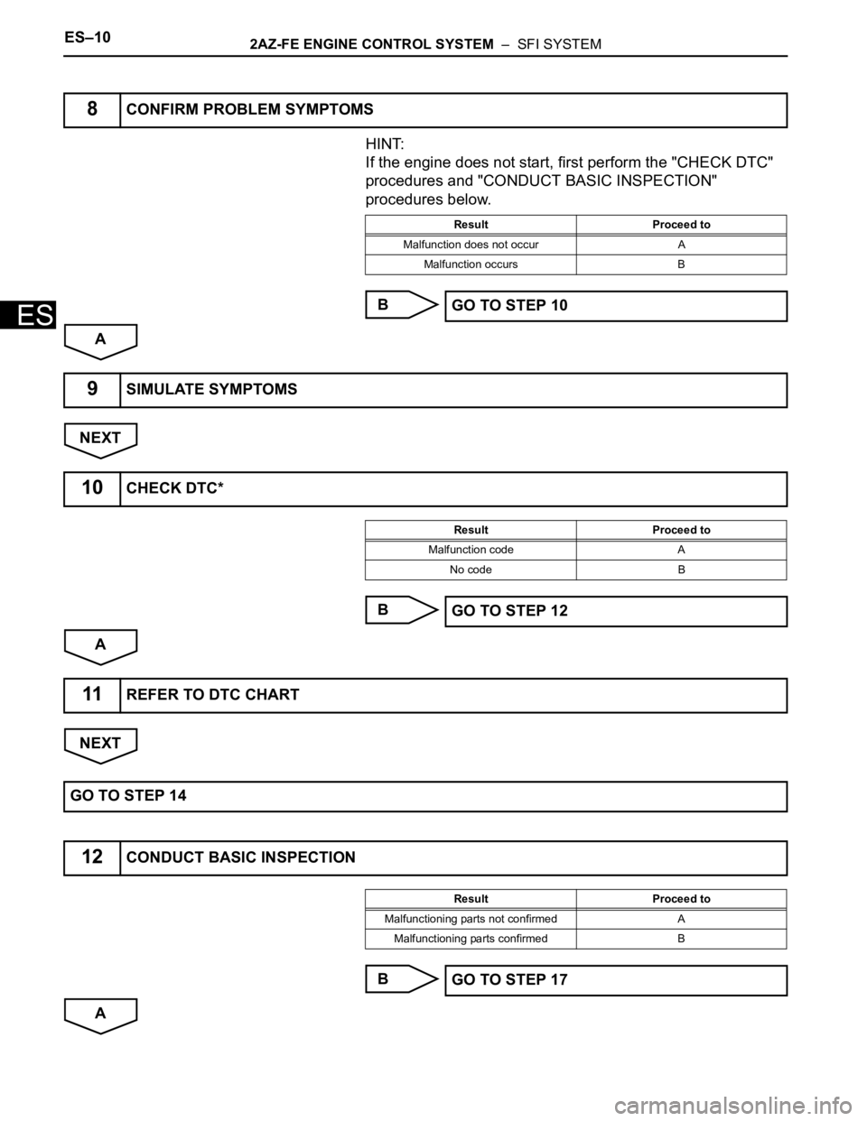
HINT:
If the engine does not start, first perform the "CHECK DTC"
procedures and "CONDUCT BASIC INSPECTION"
procedures below.
B
A
NEXT
B
A
NEXT
B
A
8CONFIRM PROBLEM SYMPTOMS
Result Proceed to
Malfunction does not occur A
Malfunction occurs B
GO TO STEP 10
9SIMULATE SYMPTOMS
10CHECK DTC*
Result Proceed to
Malfunction code A
No code B
GO TO STEP 12
11REFER TO DTC CHART
GO TO STEP 14
12CONDUCT BASIC INSPECTION
Result Proceed to
Malfunctioning parts not confirmed A
Malfunctioning parts confirmed B
GO TO STEP 17
Page 465 of 2000
2AZ-FE ENGINE CONTROL SYSTEM – SFI SYSTEMES–11
ES
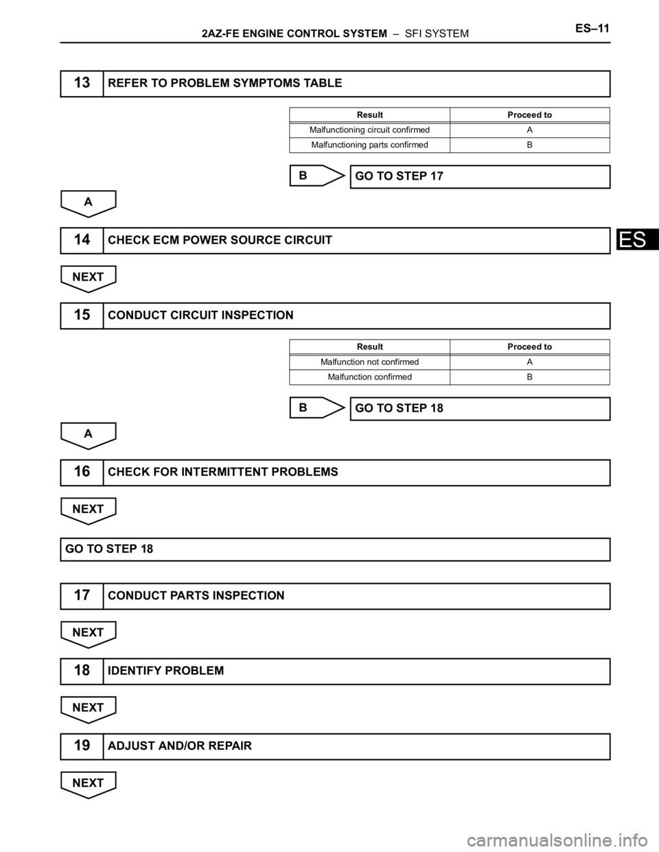
B
A
NEXT
B
A
NEXT
NEXT
NEXT
NEXT
13REFER TO PROBLEM SYMPTOMS TABLE
Result Proceed to
Malfunctioning circuit confirmed A
Malfunctioning parts confirmed B
GO TO STEP 17
14CHECK ECM POWER SOURCE CIRCUIT
15CONDUCT CIRCUIT INSPECTION
Result Proceed to
Malfunction not confirmed A
Malfunction confirmed B
GO TO STEP 18
16CHECK FOR INTERMITTENT PROBLEMS
GO TO STEP 18
17CONDUCT PARTS INSPECTION
18IDENTIFY PROBLEM
19ADJUST AND/OR REPAIR
Page 467 of 2000

2AZ-FE ENGINE CONTROL SYSTEM – SFI SYSTEMES–13
ES
CHECK FOR INTERMITTENT
PROBLEMS
HINT:
Inspect the vehicle's ECM using check mode. Intermittent
problems are easier to detect with the intelligent tester when
the ECM is in check mode. In check mode, the ECM uses 1
trip detection logic, which is more sensitive to malfunctions
than normal mode (default), which uses 2 trip detection logic.
1. Clear the DTCs (see page ES-35).
2. Switch the ECM from normal mode to check mode using
the intelligent tester (see page ES-38).
3. Perform a simulation test.
4. Check and wiggle the harness(es), connector(s) and
terminal(s).
Page 468 of 2000
ES–142AZ-FE ENGINE CONTROL SYSTEM – SFI SYSTEM
ES
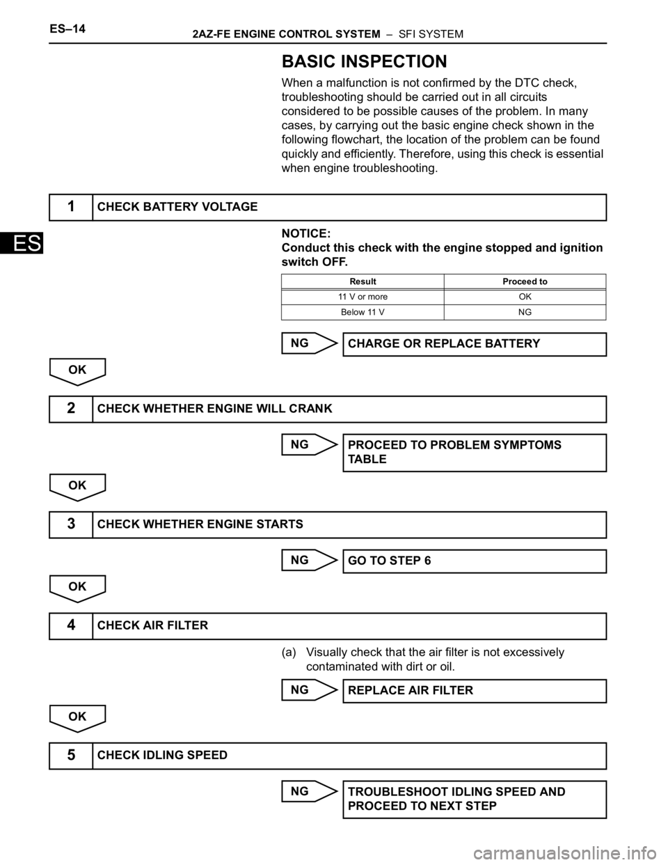
BASIC INSPECTION
When a malfunction is not confirmed by the DTC check,
troubleshooting should be carried out in all circuits
considered to be possible causes of the problem. In many
cases, by carrying out the basic engine check shown in the
following flowchart, the location of the problem can be found
quickly and efficiently. Therefore, using this check is essential
when engine troubleshooting.
NOTICE:
Conduct this check with the engine stopped and ignition
switch OFF.
NG
OK
NG
OK
NG
OK
(a) Visually check that the air filter is not excessively
contaminated with dirt or oil.
NG
OK
NG
1CHECK BATTERY VOLTAGE
Result Proceed to
11 V or more OK
Below 11 V NG
CHARGE OR REPLACE BATTERY
2CHECK WHETHER ENGINE WILL CRANK
PROCEED TO PROBLEM SYMPTOMS
TA B L E
3CHECK WHETHER ENGINE STARTS
GO TO STEP 6
4CHECK AIR FILTER
REPLACE AIR FILTER
5CHECK IDLING SPEED
TROUBLESHOOT IDLING SPEED AND
PROCEED TO NEXT STEP
Page 469 of 2000
2AZ-FE ENGINE CONTROL SYSTEM – SFI SYSTEMES–15
ES
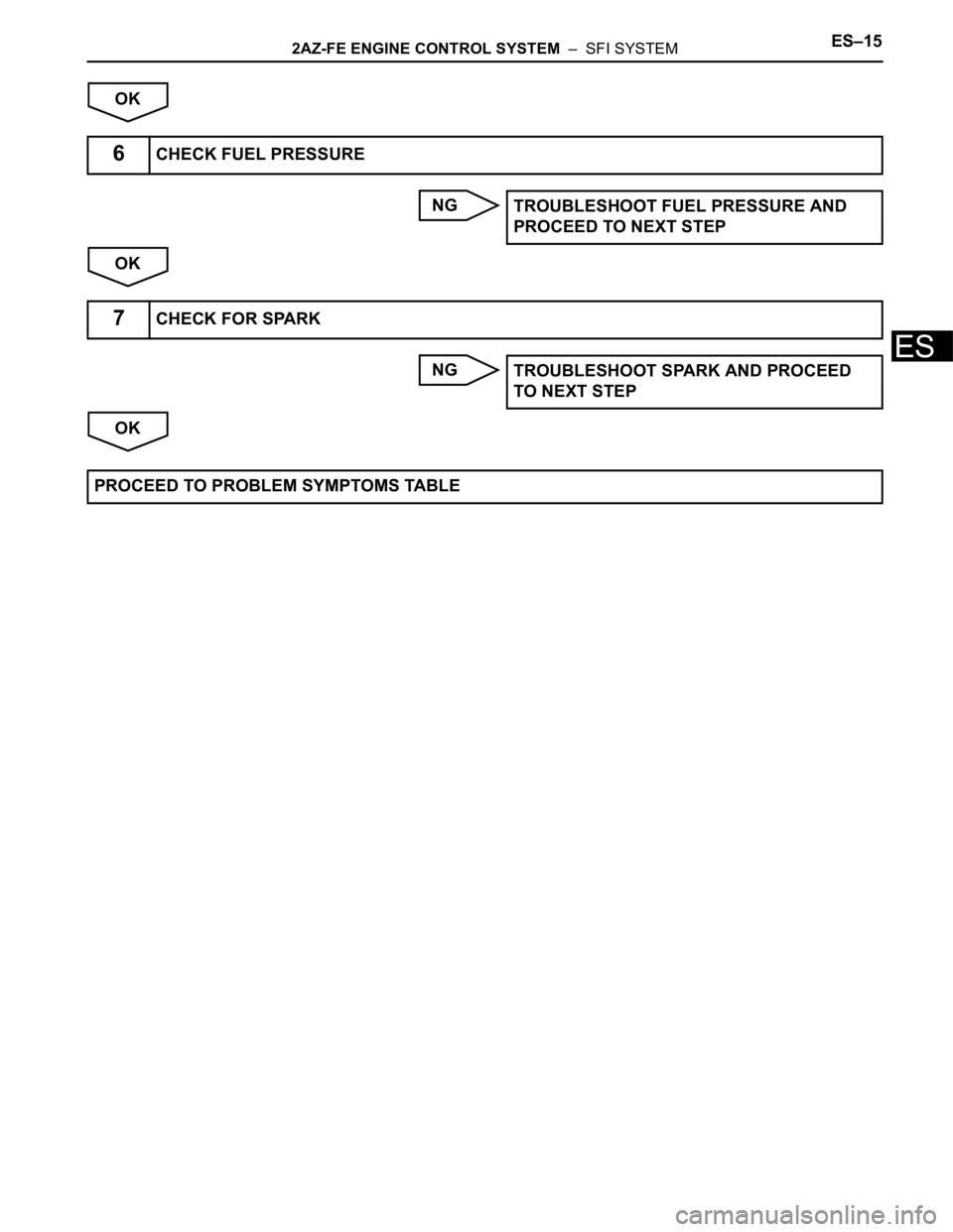
OK
NG
OK
NG
OK
6CHECK FUEL PRESSURE
TROUBLESHOOT FUEL PRESSURE AND
PROCEED TO NEXT STEP
7CHECK FOR SPARK
TROUBLESHOOT SPARK AND PROCEED
TO NEXT STEP
PROCEED TO PROBLEM SYMPTOMS TABLE
Page 475 of 2000
2AZ-FE ENGINE CONTROL SYSTEM – SFI SYSTEMES–21
ES
CHECKING MONITOR STATUS
The purpose of the monitor result (mode 06) is to allow
access to the results of on-board diagnostic monitoring tests
of specific components/systems that are not continuously
monitored. Examples are catalysts, evaporative emissions
(EVAP) and thermostats.
The monitor result allows the OBD II scan tool to display the
monitor status, test value, minimum test limit and maximum
test limit. These data are displayed after the vehicle has been
driven to run the monitor.
When the test value is not between the minimum and
maximum test limits, the ECM (PCM) interprets this as a
malfunction. If the test value is on the borderline of the test
limits, the component is likely to malfunction in the near
future.
Perform the following instruction to view the monitor status.
Although this instruction refers to the Lexus/Toyota diagnostic
tester, it can be checked using a generic OBD II scan tool.
Refer to your scan tool operator's manual for specific
procedural information.
1. PERFORM MONITOR DRIVE PATTERN
(a) Connect the intelligent tester to the DLC3.
(b) Turn the ignition switch and the tester ON.
(c) Clear the DTCs (see page ES-35).
(d) Run the vehicle in accordance with the applicable
drive pattern described in READINESS MONITOR
DRIVE PATTERN (see page ES-19). Do not turn the
ignition switch OFF.
NOTE:
The test results will be lost if the ignition
switch is turned OFF.
2. ACCESS MONITOR RESULT
(a) Select the following items from the intelligent tester
menus: DIAGNOSIS, ENHANCED OBD II,
MONITOR INFO and MONITOR RESULT. The
monitor status appears after the component name.
• INCMP: The component has not been monitored
yet.
• PASS: The component is functioning normally.
• FAIL: The component is malfunctioning.
(b) Confirm that the component is either PASS or FAIL.
(c) Select the component and press ENTER. The
accuracy test value appears if the monitor status is
either PASS or FAIL.
3. CHECK COMPONENT STATUS
(a) Compare the test value with the minimum test limit
(MIN LIMIT) and maximum test limit (MAX LIMIT).
Page 479 of 2000
2AZ-FE ENGINE CONTROL SYSTEM – SFI SYSTEMES–25
ES
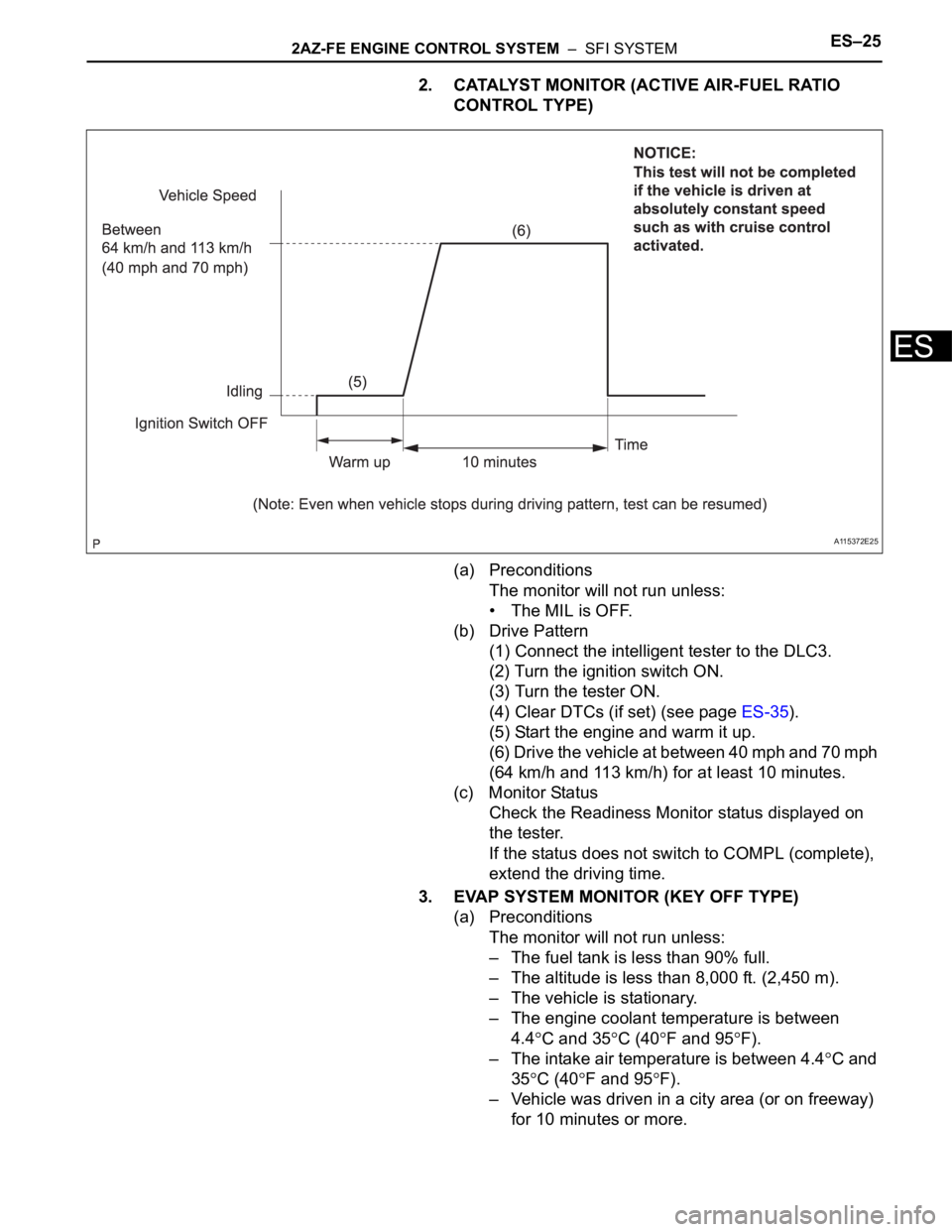
2. CATALYST MONITOR (ACTIVE AIR-FUEL RATIO
CONTROL TYPE)
(a) Preconditions
The monitor will not run unless:
• The MIL is OFF.
(b) Drive Pattern
(1) Connect the intelligent tester to the DLC3.
(2) Turn the ignition switch ON.
(3) Turn the tester ON.
(4) Clear DTCs (if set) (see page ES-35).
(5) Start the engine and warm it up.
(6) Drive the vehicle at between 40 mph and 70 mph
(64 km/h and 113 km/h) for at least 10 minutes.
(c) Monitor Status
Check the Readiness Monitor status displayed on
the tester.
If the status does not switch to COMPL (complete),
extend the driving time.
3. EVAP SYSTEM MONITOR (KEY OFF TYPE)
(a) Preconditions
The monitor will not run unless:
– The fuel tank is less than 90% full.
– The altitude is less than 8,000 ft. (2,450 m).
– The vehicle is stationary.
– The engine coolant temperature is between
4.4
C and 35C (40F and 95F).
– The intake air temperature is between 4.4
C and
35
C (40F and 95F).
– Vehicle was driven in a city area (or on freeway)
for 10 minutes or more.
A115372E25