TOYOTA RAV4 2006 Service Owner's Manual
RAV4 2006
TOYOTA
TOYOTA
https://www.carmanualsonline.info/img/14/57463/w960_57463-0.png
TOYOTA RAV4 2006 Service Owner's Manual
Page 882 of 2000
LU–222GR-FE LUBRICATION – OIL PUMP
LU
(f) Tighten the bolts in this order: Area 1, Area 2, Area
3, Area 4.
Torque: 21 N*m (214 kgf*cm, 15 ft.*lbf) for Area
1, 2 bolt
21 N*m (214 kgf*cm, 15 ft.*lbf) for Area 3
bolt, nut
43 N*m (438 kgf*cm, 32 ft.*lbf) for Area 4
bolt A
21 N*m (214 kgf*cm, 15 ft.*lbf) for Area 4
except bolt A
2. INSTALL CRANKSHAFT PULLEY (See page EM-126)
3. INSTALL CYLINDER HEAD COVER SUB-ASSEMBLY
(for Bank 2) (See page EM-127)
4. INSTALL NO. 1 OIL PIPE (See page EM-128)
5. INSTALL CYLINDER HEAD COVER SUB-ASSEMBLY
(for Bank 1) (See page EM-127)
6. INSTALL OIL PIPE (See page EM-127)
7. INSTALL WATER INLET HOUSING (See page CO-14)
8. INSTALL OIL PAN SUB-ASSEMBLY
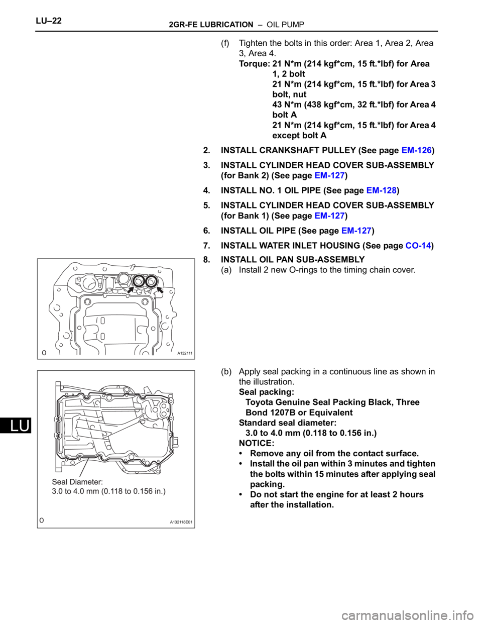
(a) Install 2 new O-rings to the timing chain cover.
(b) Apply seal packing in a continuous line as shown in
the illustration.
Seal packing:
Toyota Genuine Seal Packing Black, Three
Bond 1207B or Equivalent
Standard seal diameter:
3.0 to 4.0 mm (0.118 to 0.156 in.)
NOTICE:
• Remove any oil from the contact surface.
• Install the oil pan within 3 minutes and tighten
the bolts within 15 minutes after applying seal
packing.
• Do not start the engine for at least 2 hours
after the installation.
A132111
A132118E01
Page 1377 of 2000
DRIVE SHAFT – FRONT DRIVE SHAFT ASSEMBLY (for 2WD)DS–21
DS
(a) Install a new boot clamp to the outboard joint boot
and temporarily bend the lever.
NOTICE:
When temporarily bending the lever, make sure
not to deform the band and lever.
(b) Using water pump pliers, temporarily lock the boot
clamp by clamping it down until a "click" sound is
heard.
(c) Using a plastic-faced hammer, fix the buckle into
place by tapping it. At the same time, use the
plastic-faced hammer to adjust the lift of the lever so
that the gaps between the buckle flange and lever
end flange become even.
NOTICE:
Do not strike the drive shaft forcefully with the
plastic-faced hammer.
10. INSTALL FRONT AXLE OUTBOARD JOINT BOOT RH
CLAMP
HINT:
Use the same procedures described for the LH side.
C129511
C129512
Page 1384 of 2000
DS–28DRIVE SHAFT – FRONT DRIVE SHAFT ASSEMBLY (for 2WD)
DS
(b) Using water pump pliers, temporarily lock the boot
clamp by clamping it down until a "click" sound is
heard.
(c) Using a plastic-faced hammer, fix the buckle into
place by tapping it. At the same time, use the
plastic-faced hammer to adjust the lift of the lever so
that the gaps between the buckle flange and lever
end flange become even.
NOTICE:
Do not strike the drive shaft forcefully with the
plastic-faced hammer.
C129511
C129512
Page 1407 of 2000
DRIVE SHAFT – FRONT DRIVE SHAFT ASSEMBLY (for 4WD)DS–53
DS
(a) Install a new boot clamp to the outboard joint boot
and temporarily bend the lever.
NOTICE:
When temporarily bending the lever, make sure
not to deform the band and lever.
(b) Using water pump pliers, temporarily lock the boot
clamp by clamping it down until a "click" sound is
heard.
(c) Using a plastic-faced hammer, fix the buckle into
place by tapping it. At the same time, use the
plastic-faced hammer to adjust the lift of the lever so
that the gaps between the buckle flange and lever
end flange become even.
NOTICE:
Do not strike the drive shaft forcefully with the
plastic-faced hammer.
10. INSTALL FRONT AXLE OUTBOARD JOINT BOOT
CLAMP RH
HINT:
Use the same procedures described for the LH side.
C129511
C129512
Page 1415 of 2000
DRIVE SHAFT – FRONT DRIVE SHAFT ASSEMBLY (for 4WD)DS–61
DS
(b) Using water pump pliers, temporarily lock the boot
clamp by clamping it down until a "click" sound is
heard.
(c) Using a plastic-faced hammer, fix the buckle into
place by tapping it. At the same time, use the
plastic-faced hammer to adjust the lift of the lever so
that the gaps between the buckle flange and lever
end flange become even.
NOTICE:
Do not strike the drive shaft forcefully with the
plastic-faced hammer.
C129511
C129512


